


Services on Demand
Article
 English (pdf)
 Article in xml format
 Article references
Indicators

Related links
-
 Cited by Google
 -
 Similars in Google
Share

 Permalink
Journal of the Southern African Institute of Mining and Metallurgy
On-line version ISSN 2411-9717
Print version ISSN 2225-6253
J. S. Afr. Inst. Min. Metall. vol.123 n.5 Johannesburg May. 2023
http://dx.doi.org/10.17159/2411-9717/2450/2023
PILLAR DESIGN EDITION
Simulating pillar reinforcement using a displacement discontinuity boundary element code
J.C. Esterhuyse; D.F. Malan
Department of Mining Engineering, University of Pretoria, South Africa
SYNOPSIS
In this study we explore the use of a novel numerical modelling approach to study the effect of pillar reinforcement on pillar stability. Case studies in the literature indicate that tendons, strapping of the pillars, and shotcrete or thin spray-on liners are commonly used to reinforce pillars. No clear methodology exists to select the type of support or to design the capacity of the support required, however. This has led to ongoing collapses in some mines in spite of heavy support being used to reinforce unstable pillars. A limit equilibrium model with confinement on the edge of the pillar was used to simulate the interaction of the support with the failing pillar. The model correctly predicts that an increase in confinement will lead to a decrease in the extent of pillar failure. As the displacement discontinuity boundary element method allows for the efficient solution of large-scale bord-and-pillar layouts, the effect of pillar confinement can now be studied on a mine-wide scale. Accurate calibration of the limit equilibrium model is, however, required before this method can be used for the design of effective pillar support.
Keywords: pillar reinforcment, limit equilibrium model, displacement discontinuity boundary element code.
Introduction
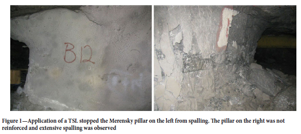
As described by Alejano et al. (2017), partially failed pillars are occasionally encountered in bord-and-pillar layouts. Selective pillar reinforcement may assist in these cases to improve the overall stability of the layout. Tendons, strapping of the pillars, and shotcrete or thin spray-on liners (TSLs) have been used in the past to reinforce pillars. An example recently recorded by the authors in a Merensky Reef bord-and-pillar mine is given in Figure 1. Extensive spalling of the pillar sidewalls was observed and TSLs were successfully used to stabilize some of the pillars. As the TSL was only selectively applied to some pillars, the benefit was clearly discernible as the unsupported pillars adjacent to the pillars with TSL reinforcement were subjected to extensive spalling.
As discussed in the next section, pillar reinforcement has not been successful in all cases and large collapses have occurred in spite of the remedial work. A methodology to better quantify the effect of pillar reinforcement in large bord-and-pillar layouts, where localized pillar failure occurs, is required. As part of this methodology, a modelling approach is required to accurately simulate the irregular pillar sizes, the pillar stress, and the effect of the support.
Simulating rock mass reinforcement is routinely done using finite difference or distinct element codes (e.g. Ghee, Zhu, and Wines, 2011; Najafi, 2021; Sinha and Walton, 2021). It is feasible to simulate a pillar which is reinforced with bolting and shotcrete using these codes. In the FLAC3D program, these structural elements can be cables or liners (Itasca, 2022). A cable may be anchored at a specific point in the grid, or grouted so that a force develops along its length. Cables may also be pretensioned. Liner elements are used to simulate thin liners for which both the normal compressive or tensile and shear frictional interaction with the rock are present. Examples such as tunnels lined with shotcrete can therefore be simulated. A major drawback of the finite difference codes is that it is very difficult to simulate large-scale tabular geometries with numerous irregular-shaped pillars. The modelling presented in the literature is typically for a single pillar only (e.g. York, 1998; Naidoo, Handley, and Leach, 2008; Jessu, Spearing, and Sharifzadeh, 2018).
In contrast, displacement discontinuity boundary element codes, such as TEXAN, can easily simulate a very large numbers of irregular pillars in a bord-and-pillar layout (e.g. Malan and Napier, 2006; Napier and Malan, 2021). The drawback of the displacement discontinuity method (DDM) is that the excavations are simulated using a 'slit'-type approximation where the excavation has a height of zero. Although this seems counterintuitive to simulate an open stope, it allows for very accurate simulations of average pillar stress (APS) and facilitates the computation of design criteria, such as energy release rate, used in the deep tabular gold mines. Although this approach works exceptionally well for simulating tabular excavations where the lateral extent of the excavations is very large, the detailed pillar failure mechanisms cannot be simulated. This is unfortunate as the edges of hard rock pillars are often fractured. One method to simulate pillar failure in the DDM codes is the so-called limit equilibrium model. For these models, it is assumed that the fractured edge of the pillar is in a state of equilibrium and that the vertical extent of this fracture zone is bounded by parting planes at the hangingwall and footwall contacts of the pillar. Based on these assumptions, it is possible to construct a differential force balance for the average reef-parallel and reef- normal tractions that obey the following relationship (see Napier and Malan, 2021):

where H is the height of the fracture zone normal to the plane of the excavation, Vσs(P) is the gradient vector of the average reef parallel stress σs at point P in the pillar while σn is the reef-normal compressive stress at point P. The parameter μι is the friction coefficient at the upper and lower parting separating the fractured rock from the intact rock above and below the pillar. Of interest is that with the implementation of this model in the DDM codes, the parameter H is now introduced as a 'pillar height' parameter. A specific limit equilibrium strength relationship, σn = f(σs), also needs to be assumed. This model, implemented in the TEXAN code, has been extensively used to simulate pillar failure (e.g. Napier and Malan, 2021; Couto and Malan, 2023).
In this paper we describe a simple extension of the limit equilibrium model to simulate the confining effect of pillar reinforcement. It was implemented in the TEXAN code by Professor John Napier. Although this approach cannot model the detailed support mechanisms available in the finite difference codes, it is still a useful method to simulate mine-scale layouts and the confining effect of pillar reinforcement, provided the necessary calibration can be done using underground observations. A case study from Santa Rosa mine in Spain is used as an example in this paper.
Examples of pillar reinforcement
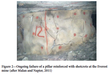
In South Africa, a number of hard rock pillar failure case studies have been conducted where attempts were made to reinforce the pillars. Figure 1 in the previous section illustrates an example where the TSL seem to have worked very well. Not all previous attempts to support the pillars were successful, however. Spencer (1999) describes the reinforcement of pillars traversed by thick clay layers using mesh and lacing with cables at the Wonderkop mine. The blocky and fractured nature of the pillars caused delays during the drilling and grouting of the support holes. Only about 70 pillars were supported. Spencer noted that the support assisted to keep the pillars together and prevented further spalling, but he speculated that the support did little to strengthen the overall pillar support system. Conditions deteriorated further and the mine was closed in 1998. The failure was partially attributed to the drilling process, which introduced additional water into the clay and probably weakened the pillars further. Couto and Malan (2023) reported another unsuccessful attempt to increase the pillar confinement using fibre-reinforced shotcrete at the Everest mine in the eastern Bushveld Complex. This attempt was also unsuccessful and a large part of the mine collapsed. Figure 2 illustrates the subsequent cracking of the shotcrete at the Everest mine as pillar failure progressed.
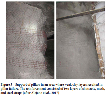
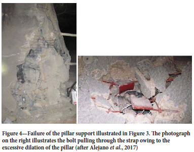
A further example of pillar support in areas with a weak clay layer in a different mine is illustrated in Figure 3. It consisted of a layer of shotcrete, bolting, mesh, steel strapping, and a further layer of shotcrete. This support unfortunately did nothing to arrest the eventual collapse of the mine. Figure 4 illustrates the failure of the support as the pillars continued to deteriorate.
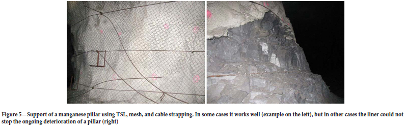
Some manganese pillars in South Africa have also been supported with TSLs in areas where the joint spacing is small. This is illustrated in Figure 5. Some of the pillars reinforced using this method continue to deteriorate, however.
Siwak (1984) reported failure in pillars in underground chalk quarries in northern France. The pillars were supported with a 6 mm thick layer of glass-fibre-reinforced resin, but the additional confinement only delayed, and did not prevent, the eventual failure. In contrast, Esterhuizen, Dolinar, and Ellenberger (2011) reported the apparently successful use of rib pillar support, such as chain link mesh and bolts to prevent further deterioration of the pillars in underground stone mines in the USA. Wojtkoviak, Rai, and Bonvallet, (1985) conducted a study of the effectiveness of various approaches of pillar reinforcement based on laboratory test samples. These included mine fill, rockbolting, shotcrete or resin spraying, and 'steel banding' (pillar strapping). The tests illustrated an increase in pillar strength using all these techniques, but unfortunately the study did not investigate the post-failure behaviour of pillars. A review of pillar reinforcement is also given in Alejano et al. (2017). In the Santa Rosa Mine in Spain, selected pillars were reinforced by using tensioned cables. This example is explored in more detail below. It should be noted that this proposed method will not be universally applicable as it will not prevent creep or extrusion phenomena. Andrews, Butcher, and Ekkerd (2020) reported on the reinforcement of the yield pillars in the destress cuts at the South Deep gold mine. The unsupported pillars deteriorated with time and were subsequently supported using bolts, mesh, and shotcrete. The support consists of dynamic friction bolts and 5.6 mm gauge weldmesh. The support was installed down the sidewalls of the pillars to 1.5 m from the footwall at a spacing of 1.4 m χ 1.2 m. Shotcrete was later added to reduce pillar unravelling below the mesh line. The methodology used to design this reinforcement is not known. An earlier study at the same mine, based on visual observations by Sengani (2018), indicated that the bolt-reinforced in-stope pillars were subjected to extensive spalling and fracturing during seismic events, while bolt-reinforced and shotcreted pillars suffered only minor or no damage. Examination using a borehole camera showed that the pillar fractures were only minor when the pillar was supported using both bolt reinforcement and fibre shotcrete.
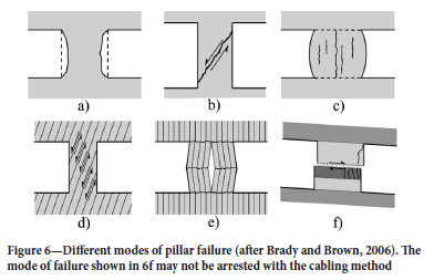
Figure 6 shows typical pillar failure modes presented by Brady and Brown (2006). This is included to give some insight as to why pillar support may work in some cases and not in others. For pillars in massive rock where there are no weak contacts with the hangingwall and footwall, failure typically occurs by spalling from the pillar surfaces (see Figure 6a). This leads to a gradual reduction of the pillar width and will increase the stress on the pillar. For small width/height ratios, an inclined shear failure may develop in the pillar (Figure 6b). If there are weak contacts present between the pillar and the hangingwall and footwall, axial splitting of the pillar may occur (Figure 6c). If there is a joint set with a dip angle larger than the friction angle, the pillar can fail owing to slip on these joints (Figure 6d). In contrast, if the joints are sub-parallel to the loading axis, the pillar may fail by buckling of the slabs (Figure 6e). Alejano et al. (2017) hypothesized that for the first five case cases in Figure 6, cabling reinforcement will contribute to an increase in pillar stability. The deformation of the pillar will tension the cables, increasing the confining stress and, consequently, the pillar strength. This may work provided the lateral dilation and force exerted by the pillar is less than the capacity of the support. If there is a weak material forming intermediate layers or filling the discontinuities as shown in Figure 6f, the pillar support may prove ineffective, as was illustrated by the mine collapses in Southern Africa described above.
To investigate the effectiveness of TSLs for reinforcing pillars, Qiao et al. (2014) conducted laboratory testing of TSL-coated rock samples. The results illustrated a significant increase in strength for the TSL-encapsulated specimens. The authors concluded that the reinforcement appears to be more effective for weaker rocks than for stronger rocks. Rock reinforcement using TSLs is effective in cases where the tensile strength of the TSL material is larger than that of the rock. A laboratory study was also conducted by Dondapati et al., (2022). They found that a 5 mm fibreglass-reinforced TSL could increase the peak strength of concrete samples by 30%, and of coal samples by nearly 50%.
In summary, from the literature study it is clear that pillar reinforcement may work in some cases and may increase the strength of the pillars. A methodology to design the required support capacity and select the most appropriate support elements is not readily available, however. The next section explores a novel modelling approach that may assist in this regard.
A limit equilibrium model to simulate the effect of pillar confinement
A detailed description of the limit equilibrium model and its implementation in the TEXAN code has been given in a number of papers and it will not be repeated here (e.g. see Napier and Malan, 2014, 2021; Couto and Malan, 2022). The important extension to the model discussed in this paper is the application of a confinement stress on the pillar edge to simulate the effect of pillar reinforcement.
The force equilibrium in the failed edge of a pillar is shown in Figure 7. The limit equilibrium model assumes that there is a frictional interface at the contacts between the pillar and the hangingwall and footwall. Note the confinement stress, au, applied by the pillar reinforcement.
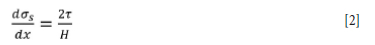
As described above, an important extension of the model illustrated in Figure 7 is that a confining stress, σh, is applied on the skin of the pillar at x = 0 as a result of the pillar reinforcement. The seam-parallel stress component σs increases as x increases. It is assumed that the fractured rock between the dotted lines in Figure 7 is in equilibrium. From the balance of forces, it can be shown that the following differential equation applies if the width of the slice in equilibrium tends to zero:
The model assumes that there are frictional partings between the pillar and the hangingwall and footwall and the following slip condition applies:

where μ1 is the coefficient of friction at the interface of the pillar contacts and f is the friction angle on the interfaces. For the limit equilibrium model, a strength criterion for the failure zone needs to be adopted and it is assumed that σn is related to the seam- parallel stress component σs by the following relationship:

where σc and m are specified constants. In the TEXAN code, a model with two strength relationships is implemented. The failure relationship for the intact pillar material is given by the parameters m = mi and σc = σci. For the failed pillar material, the parameters m = mf and σc = σcf are adopted. When calibrating these parameters, the requirements of mi > mf and σiC > σcf must be met.
Substituting Equations [4] and [3] into Equation [2] and integrating gives the following solution:
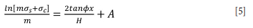
where A is the integration constant. The effect of the pillar reinforcement is now taken into account and the constant A is derived from Equation [5] by applying the boundary condition σs = σh when x = 0.
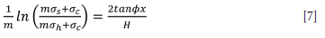
This gives:

This can be inserted into Equation [5] and simplified to give
and furthermore
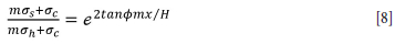
From Equation [8], the solution of the reef-parallel stress is derived as
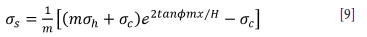
From Equations [9] and (4), the solution for On is given as:

Equation [10] implies that on the skin of the pillar when x = 0:
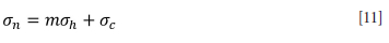
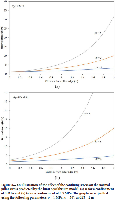
This equation is of a similar shape to that of Equation [4] but now includes the confining stress σh. Interestingly, the slope parameter m is in this equation and the model will predict large normal stresses on the edge of the pillar for high values of m and large confining stresses. This is illustrated in Figure 8. Note the rapid increase in normal stress for m = 3 and σh = 0.5 MPa. Also note the characteristic exponential increase in normal stress in the failed zone of the pillar as predicted by the limit equilibrium model.
It should be noted that the model derived above has some limitations and these should be carefully considered when using this approach in a numerical model. Tendons will apply point loads, whereas the derivation above assumes a uniform load, σh, being applied on the edges of the pillar. The use of stiff strapping and liners between the bolts may result in a more uniform application of the tendon load. This limitation of the limit equilibrium model nevertheless always needs to be considered for different pillar reinforcement methods and the resulting distribution of confinement load on the pillar. One possibility would be to downgrade the value of σh when only tendons without load spreaders are used as support, but some experimentation and measurements will be required to determine realistic downgrade factors. As future work, pillar failure with and without tendon support should be simulated in a code such as FLAC3D and this should be compared to the confinement approach in the limit equilibrium model. Furthermore, the model above assumes that the support is 'active' and that it applies an immediate confinement to the pillar. This may be applicable if the tendons are prestressed, for example, but the numerical model needs to be extended in future to simulate the pillar dilation and the stiffness of the pillar support. This will enable the simulation of the gradual build-up of confinement as the pillar fails and dilates. As a final comment, it should be noted that these limitations are the result of the nature of displacement discontinuity boundary element codes, where the tabular excavations are simulated as a 'slit' without a finite height. The limit equilibrium model is simply an elegant method to introduce pillar failure in this modelling approach and its benefit is that it can simulate a large number of irregularly shaped pillars on a mine-wide scale.
For a completely failed pillar, Equation [10] can be used as an illustration of the effect of confinement on the residual strength of the crushed pillar. Assume the width of the pillar is as illustrated in Figure 7 and the failure on the pillar edge and the normal stress profile illustrated in Figure 8 will be symmetrical for both sides of the pillar. As the pillar is completely failed, Wc = 0, and therefore w = 2L (see Figure 7). The residual APS can then be computed by integrating Equation [10] over the width of the fracture zone pillar:
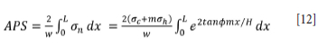
By considering that for the completely failed pillar, L = w/2, it follows from Equation [12] that:
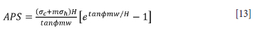
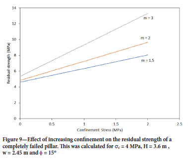
This equation assumes that the pillar support does not fail and that it is capable of supplying the specified confinement, regardless of the amount of pillar dilation and unravelling. Equation [13] is plotted in Figure 9 for the parameters given in the caption. It is clear that increasing confinement will increase the residual strength of the pillar and a higher slope angle for the strength envelope of the failure criterion will result in a larger residual strength.
As the model seems to be useful to simulate pillar confinement, the next section explores an actual case study of pillar confinement in the Santa Rosa mine.
A numerical modelling study of pillar failure and reinforcement at the Santa Rosa mine
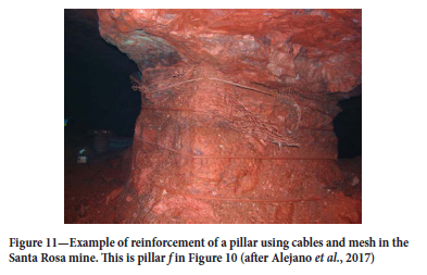
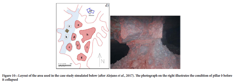
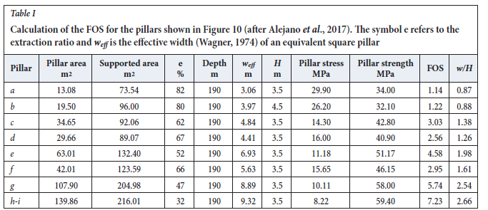
Alejano et al. (2017) describe a case study of a room-and-pillar layout in the Santa Rosa mine. The mine exploits a haematite seam that varies in thickness from 2 m to 10 m. The layout of the area of interest is shown in Figure 10. The depth of mining was 190 m. The small pillars, labelled a and b, collapsed during February 2012. In 2012 and 2013, pillars c, d, and f were strapped using cables. The strapping of the pillars is shown in Figure 11. Alejano et al. (2017) estimated the factor of safety (FOS) on the pillars using Hedley and Grant (1972) for the pillar strength and tributary area theory (TAT) to estimate the pillar stress. This information is given in Table I. Pillars h and i were part of a single pillar before it was split and which is still included as a single pillar in the table. The pillar height varied from 3.5 m to 4.5 m. An average height of 3.6 m was therefore used for the numerical modelling described in the section below. The calculated FOS values for pillars a and b are close to unity and this therefore correctly predicted that these two pillars were at risk of collapsing.
In terms of the mechanism of pillar failure, a horizontal parting is visible for the pillar in Figure 10. The material also appears to be highly jointed and it seems as if the horizontal parting is facilitating the unravelling of discontinuous material. This most likely occured in a time- dependent fashion, but no data is available in this regard and it will therefore not be considered in this study.
The case study above was selected for modelling as the cable strapping seemed to arrest the deterioration of the pillars. Pillar f in Figure 11 was supported during June 2013. The extensive spalling of the pillar can be seen in the figure when comparing the width of the strapped portion to the original size of the pillar visible in the upper portion of the photograph. No further deterioration was noted after the strapping, and observations made three years later during January 2016 confirmed the stability of the pillar.
The TEXAN code used in this study is a displacement discontinuity boundary element code that was specifically developed to simulate a large number of small pillars in tabular layouts (Malan and Napier, 2006). It allows for the use of triangular boundary elements, which circumvents the problem of 'partially mined' elements encountered using square element shapes. The simplified 'two-dimensional' limit equilibrium model described above had to be extended for use in the TEXAN code to simulate the actual irregular pillar shapes in three dimensions (see Napier and Malan, 2021). A useful feature of the TEXAN code is that it can simulate pillar failure behaviour on a stope-wide scale by using the limit equilibrium model. Details of the use of this constitutive model can be found in du Plessis, Malan, and Napier (2011) and Napier and Malan (2012, 2014, 2018). A drawback of the model is that the failure is restricted to the plane of the reef. It is nevertheless an elegant method to simulate failure on the reef horizon in a large mine-wide model.
The geometry simulated in TEXAN is illustrated in Figure 12. This layout represents the 2012 geometry prior to the collapse of pillars a and b.
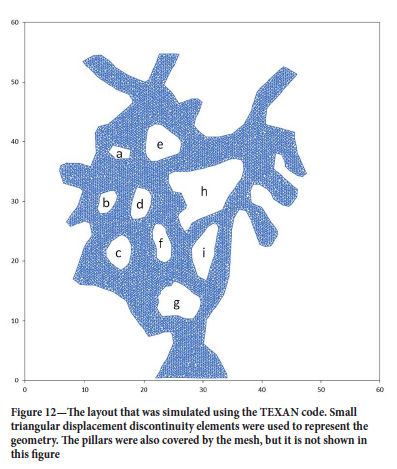
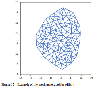
The pillars had to be covered with a triangular mesh to enable the calculation of the APS. Figure 13 illustrates the mesh for pillar c. The mesh used for the pillars and mined areas had to be small to ensure an accurate calculation of the APS values (see Napier and Malan, 2011) and also that the limit equilibrium model provides an accurate simulation of the extent of failure in the pillars (Malan and Napier, 2018). The element sizes used for this study were therefore small, approximately 0.09 m2 on average.
Numerical modelling using rigid pillars
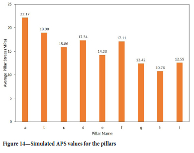
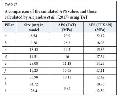
As a first modelling step, the pillars were not allowed to fail and were simulated as 'rigid' pillars that were not allowed to deform. This enabled an accurate calculation of the average pillar stresses. Figure 14 illustrates the simulated APS values for the pillars. Table II illustrates the pillar sizes and compares the simulated APS values with those given by Alejandro et al. (2017). Although there is rough agreement between the values, the numerically simulated values are more accurate as the effect of the abutments is taken into account. Tributary area theory is a crude assumption for a geometry with such a small overall span.
Simulating pillar failure using a limit equilibrium model
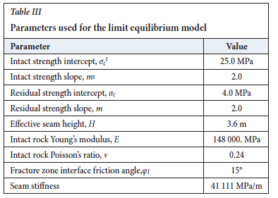
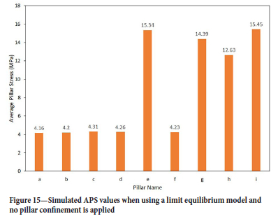
The limit equilibrium model currently implemented in TEXAN requires a large number of parameters to be calibrated, and these are listed in Table III. The values in Table III are only crude approximations for the Santa Rosa mine as they were derived from values calibrated by the authors for a different hard-rock mine where pillar failure occurred. The rigid pillar simulation described above was repeated using this limit equilibrium failure model. No confining stress was applied to the pillars for the first simulation. The simulated APS values are illustrated in Figure 15. These can be compared to Figure 14. For the pillars that completely failed (shown in Figure 16), the stress decreased to a residual value slightly above 4 MPa. These residual strength values are determined by the residual strength and slope parameter values (see Table III). The pillars that did not fail (e, g, u, and i) illustrate an increase in stress as they carry some of the additional load originating from the failed pillars (a, b, c, d, f).
In the subsequent simulations, the effect of pillar confinement was modelled by gradually increasing the confinement, σh. The amount of confinement applied by the various types of support needs to be quantified in future, so these preliminary runs were done simply to provide a qualitative illustration of the effect of confinement. Figures 16, 17, and 18 illustrate the decrease in failure in the pillars for increasing confinement. This is an encouraging result and the approach described in this paper therefore seems to be a useful method to simulate the effect of pillar confinement using displacement discontinuity codes. Of interest is that the 0.02 MPa confinement is of the same order as the value of 0.05 MPa measured by Galvin and Wagner (1982) at their experimental site where ash fill was used to reinforce coal pillars.
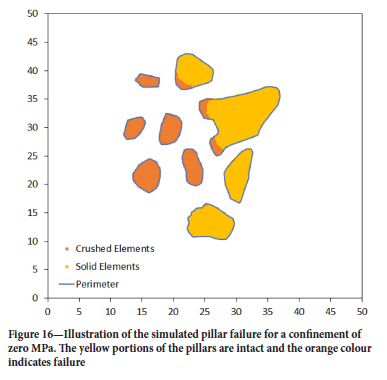
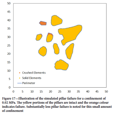
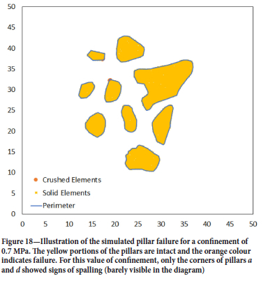
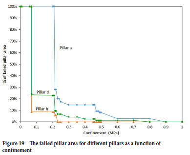
Figure 19 illustrates the decrease in pillar failure for increasing confinement. As expected, the smallest pillar (pillar a) requires a higher value of confinement to reduce the extent of failure compared to pillars b and d. The stress acting on pillar a is higher owing to its small size (Figure 14 and Table II) and a higher confinement is therefore required. Also interesting is that for the selected limit equilibrium parameters, the small pillars, and the selected depth, there is a 'threshold' value of confinement that causes a sudden, significant decrease in the extent of failure.
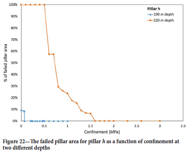
To illustrate the difficulty of designing appropriate pillar confinement, the layout was also simulated at a greater depth of 220 m using the same limit equilibrium parameters for the rock material. The increase in confinement required at this greater depth to stabilize the pillars are shown in Figures 20, 21, and 22. Pillar h is larger and requires less confinement.
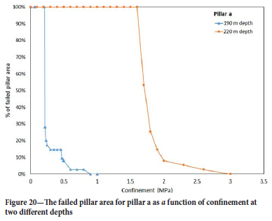
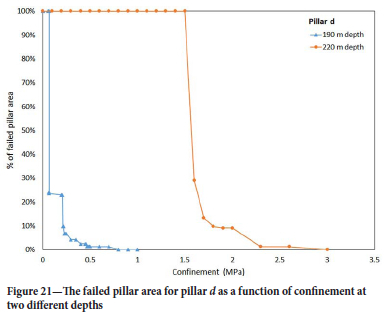
The decrease in the extent of failure is also more gradual for this pillar with increasing confinement at the greater depth of 220 m.
In summary, these simulations indicate that the design of pillar confinement to prevent pillar spalling will be dependent on the pillar size, the strength of the pillar material, and depth of the excavation (the stress acting on the pillar). Simplified design rules for pillar reinforcement will therefore be difficult to provide and every case should be assessed on its own merits. Numerical modelling will have to be conducted to determine the various parameters. For the approach described in this paper, the pillar strength will have to be assessed to calibrate the limit equilibrium model. Furthermore, the confinement that can be supplied by the various pillar support systems needs to be known.
Conclusions
Tendons, strapping of the pillars and shotcrete or thin spray-on liners are occasionally used to reinforce pillars in bord-and-pillar layouts. A trial-and-error approach is mostly followed in industry to design this type of support. In some cases, the reinforcement does not work and ongoing pillar deterioration occurs. A methodology therefore needs to be developed to determine the capacity of the required support and in which of the cases pillar reinforcement will work.
A limit equilibrium model, with the option to apply confinement on the edge of the fracture zone, was investigated as a modelling methodology to study pillar confinement. The model correctly predicted that an increase in confinement leads to a decrease in the extent of pillar failure and therefore a more stable layout. As the displacement discontinuity boundary element method allows for the efficient solution of large-scale bord-and-pillar layouts, the effect of pillar confinement can now be studied in the context of real pillar layouts. The appropriate support capacity of the pillar reinforcement can be determined using a quantitative approach.
In its current form the model is useful to simulate the effect of pillar confinement and to select the required support capacity of the pillar reinforcement, provided an accurate calibration of the model can be done. This may be difficult, however, and further work is needed in this regard. Selecting an appropriate value for the confinement,σh, applied by the support may be particularly challenging. Furthermore, the work presented in this paper assumes that the support is 'active' and it applies an immediate confinement to the pillar. This needs to be extended to simulate the pillar dilation and the stiffness of the pillar support. This will enable the simulation of the gradual build-up of confinement as the pillar fails and dilates. Further work also needs to be done to obtain more accurate calibrations of the limit equilibrium model for different pillar types. The confinement applied by various types of support systems, comprising bolts, strapping, and liners needs to be determined.
Acknowledgements
This work forms part of the PhD study of Johann Esterhuyse at the University of Pretoria. The authors would like to thank Professor John Napier for his kind assistance and the original implementation of the confinement model in the TEXAN code.
References
Andrews, P.G., Butcher, R.J., and Ekkerd, J. 2020. The geotechnical evolution of deep-level mechanized destress mining at South Deep mine. Journal of the Southern African Institute of Mining and Metallurgy, vol. 120. pp. 33-40. [ Links ]
Alejanö, L.R., Arzúa, J., Caströ-filgueira, U., and Malan, F. 2017. Strapping of pillars with cables to enhance pillar stability. Journal of the Southern African Institute of Mining and Metallurgy, vol. 117, no. 6. pp. 527-540. [ Links ]
Brady, B.H.G. and Brown, E.T. 2006. Rock Mechanics for Underground Mining. 3rd edn. Springer. [ Links ]
Cöutö, P.M. and Malan, D.F. 2023. A limit equilibrium model to simulate the large-scale pillar collapse at the Everest Platinum Mine, Rock Mechanics and Rock Engineering, vol. 56. pp. 183-197. [ Links ]
Döndapati, G.P., Deb, D., Pörter, I., and Karekal, S. 2022. Improvement of Strength-Deformability Behaviour of Rock-Like Materials and Coal Using Fibre-Reinforced Thin Spray-on Liner (FR-TSL). Rock Mechanics and Rock Engineering, vol. 55. pp. 3997-4013. [ Links ]
Du Plessis, M., Malan, D.F., and Napier, J.A.L. 2011. Evaluation of a limit equilibrium model to simulate crush pillar behaviour. Journal of the Southern African Institute of Mining and Metallurgy, vol. 111. pp. 875-885. [ Links ]
Esterhuizen, G.S., Dölinar, D.R., and Ellenberger, J.L. 2011. Pillar strength in underground stone mines in the United States. International Journal of Rock Mechanics and Mining Sciences, vol. 48, no. 1. pp. 42-50. [ Links ]
Galvin, J.M. and Wagner, H. 1982. Use of ash to improve strata control in bord and pillar workings. Proceedings of the Symposium on Strata Mechanics, Newcastle-upon-Tyne, 5-7 April 1982. Farmer, I.W. (ed.). Elsevier, Amsterdam. [ Links ]
Ghee, E.H., Zhu, B.T., and Wines, D.R. 2011. Analysis of twin road tunnels using numerical modelling techniques. Proceedings of the 14th Australasian Tunnelling Conference: Development of Underground Space. Ausyralasian Institute of Mining and Metallurgy, Melbourne. pp. 443-454. [ Links ]
Hedley, D.G.F. and Grant, F. 1972. Stope-and-pillar design for the Elliot Lake Uranium Mines. Bulletin of the Canadian Institute of Mining and Metallurgy, vol. 65. pp. 37-44. [ Links ]
Itasca Consulting Group, Inc. 2022. FLAC3D Documentation,Minneapolis, MN. [ Links ]
Jessu, K.V., Spearing A.J.S, and Sharifzadeh, M. 2018. A parametric study of blast damage on hard rock pillar strength. Energies, vol. 11. 1901. [ Links ]
Malan D.F. and Napier J.A.L. 2006. Practical application of the Texan code to solve pillar design problems in tabular excavations. Proceedings of the SANIRE Symposium "Facing the challenges", Rustenburg, South African National Institute of Rock Engineering. pp. 55-74. [ Links ]
Malan, D.F. and Napier, J.A.L. 2011. The design of stable pillars in the Bushveld mines: A problem solved? Journal of the Southern African Institute of Mining and Metallurgy, vol. 111. pp. 821-836. [ Links ]
Malan, D.F. and Napier, J.A.L. 2018. Reassessing continuous stope closure data using a limit equilibrium displacement discontinuity model. Journal of the Southern African Institute of Mining and Metallurgy, vol. 118, no. 3. pp. 227-234. [ Links ]
Motamedi, M.H. and Najafi, M. 2021. A numerical simulation of bolt grouting reinforcement for reducing the optimum dimensions of jointed hard rock pillars in Faryab chromite mine (Iran). Geotechnical and Geological Engineering, vol 39. pp. 4747-4763. [ Links ]
Naidoo, K., Handley, M.F., and Leach, A.P. 2008. Applying numerical modelling to pillar design in South African mines - An initial study. SHIRMS 2008: Proceedings of the First Southern Hemisphere International Rock Mechanics Symposium. Potvin, Y., Carter, J., Dyskin, A., and Jeffrey, R. (eds.). Australian Centre for Geomechanics, Perth. pp. 379-390. [ Links ]
Napier, J.A.L. and Malan, D.F. 2011. Numerical computation of average pillar stress and implications for pillar design. Journal of the Southern African Institute of Mining and Metallurgy, vol. 111. pp. 837-846. [ Links ]
Napier, J.A.L. and Malan, D.F. 2012. Simulation of time-dependent crush pillar behaviour in tabular platinum mines. Journal of the Southern African Institute of Mining and Metallurgy, vol. 112. pp. 711-719. [ Links ]
Napier, J.A.L. and Malan, D.F. 2014. A simplified model of local fracture processes to investigate the structural stability and design of large-scale tabular mine layouts. Proceedings of the 48th US Rock Mechanics / Geomechanics Symposium, Minneapolis, MN. American Rock Mechanics Association, Alexandria, VA. [ Links ]
Napier, J.A.L. and Malan D.F. 2018. Simulation of tabular mine face advance rates using a simplified fracture zone model. International Journal of Rock Mechanics and Mining Sciences, vol. 109. pp. 105-114. [ Links ]
Napier, J.A.L. and Malan D.F. 2021. A limit equilibrium model of tabular mine pillar failure. Rock Mechanics and Rock Engineering, vol. 54. pp. 71-89. [ Links ]
Qiao, Q., Nemcik, J., Porter, I., and Baafi, E. 2014. Laboratory investigation of support mechanism of thin spray-on liner for pillar reinforcement. Geotechnique Letters, vol. 4. pp. 317-321. [ Links ]
Sengani, F. 2018. The performance of bolt-reinforced and shotcreted in-stope pillar in rockburst-prone areas. International Journal of Mining and Geo-Engineering, vol. 52, no. 2. pp. 105-117. [ Links ]
Sinha, S. and Walton, G. 2021. Modelling the behaviour of a coal pillar rib using Bonded Block Models with emphasis on ground-support interaction. International Journal of Rock Mechanics and Mining Sciences, vol. 148. doi: 10.1016/j.ijrmms.2021.104965 [ Links ]
Siwak J.M. 1984. Carrieres de craie du Nord de la France. Comportement des piliers et confortation par gunitage. [Shale quarries in northern France. Pillar behaviour and shotcrete support]. PhD thesis. Université des Sciences et Techniques de Lille [in French]. [ Links ]
Spencer, D. 1999. A case study of a pillar system failure at shallow depth in a chrome mine. Proceedings of SARES99,2nd Southern African Rock Engineering Symposium. Hagan, T.O. (ed.). South African National Institute of Rock Engineering. pp. 53-59. [ Links ]
Wagner, H. 1974. Determination of the complete load-deformation characteristics of coal pillars. Proceedings of the 3rd ISRM Conference, Denver, CO. Vol IIB, Advances in Rock Mechanics, International Society for Rock Mechanics and Rock Engineering, Lisbon. pp. 1076-1081. [ Links ]
Wojtkoviak, F., Rai, M.A., and Bonvallet, J. 1985. Études expérimentales en laboratoire de différentes méthodes de renforcement des petits piliers de mine [Experimental studies in laboratory of different reinforcement methods to be applied on small mining pillars]. Bulletin of the International Association of Engineering Geology, vol. 32. pp. 131-138. [ Links ]
York, G. 1998. Numerical modelling of the yielding of a stabilizing pillar/foundation system and a new design consideration for stabilizing pillar foundations, Journal of the Southern African Institute of Mining and Metallurgy, vol. 98, pp. 281-298. [ Links ]
 Correspondence:
D.F. Malan
Email: francois.malan@up.ac.za
Received: 12 Nov. 2022
Revised: 8 June 2023
Accepted: 9 June 2023
Published: May 2023

