


Serviços Personalizados
Artigo
 Inglês (pdf)
 Artigo em XML
 Referências do artigo
Indicadores

Links relacionados
-
 Citado por Google
 -
 Similares em Google
Compartilhar

 Permalink
Journal of the Southern African Institute of Mining and Metallurgy
versão On-line ISSN 2411-9717
versão impressa ISSN 2225-6253
J. S. Afr. Inst. Min. Metall. vol.123 no.3 Johannesburg Mar. 2023
http://dx.doi.org/10.17159/2411-9717/1247/2023
PROFESSIONAL TECHNICAL AND SCIENTIFIC PAPERS
Numerical investigation into slag solidification inside an ilmenite DC arc furnace using a finite element method approach
A. MabentselaI; A. MainzaII
IUniversity of Botswana, Gaborone, Botswana. http://orcid.org/0000-0003-2976-1201
IIDepartment of Chemical Engineering, University of Cape Town, South Africa
SYNOPSIS
A finite element model of a 5 m radius DC arc ilmenite furnace in idling mode was used to test the notion that the slag solidifies when it comes in to contact with colder pig iron, thus constituting the initial step in the formation of solid slag at the slag-pig iron interface. It was found that a slag that is 150°C hotter than the pig iron does not solidify at the interface. The 150°C temperature difference between the slag and pig iron is a result of solid slag at the slag-pig iron interface, not the other way around as suggested in the literature. Calculations show that the thickness of the frozen slag at the slag-pig iron interface is 1.7 cm for the furnace used. It is proposed that slag solidification begins with the slow co-current flow of molten slag and pig iron in the outer parts of the furnace. This provides enough time for molten slag to interact with molten pig iron without solidifying. As the reduction products form due to reduction of the slag by carbon in the pig iron, the slag solidifies. This approach negates the need for the slag to solidify by merely coming into contact with an inherently colder pig iron.
Making use of a low thermal contact conductance between the slag and pig iron was found to be sufficient to numerically capture the presence of solid slag at the slag-pig iron interface and to preserve the 150°C difference between the slag and pig iron phase.
Keywords: ilmenite smelting, slag-pig iron interface, effective thermal conductivity.
Introduction
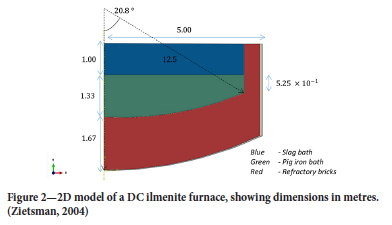
Ilmenite smelting is aimed at producing a TiO2-rich slag, which is used for pigment production, together with molten pig iron for steelmaking. Typical ilmenite feedstock contain 36- -50% TiO2, the balance consisting mainly of FeO with minor impurities. Through smelting, the TiO2 content is upgraded to a target of >85%. This upgrade takes place by reduction of the iron in ilmenite from Fe2+ to metallic iron via Equation [1]. The reducing agent used is anthracite (Bessinger, 2000; Gous, 2006).

The reaction takes place in the liquid state at slag temperatures of 1650-1700°C (Pistorius, 2008). Electric furnaces are used to generate the required temperatures. Due to the high electrical conductivity of the ilmenite feed and slag, such furnaces use an open arc configuration where the electrode is not in contact with the molten bath (Bessinger, 2000).
Figure 1 shows a generic schematic of a DC arc furnace with a single hollow electrode. The furnace is circular and consists of four distinct parts: a fixed furnace roof, detachable furnace roof dome, sidewalls, and furnace hearth. Figure 1 does not show the tap-holes.
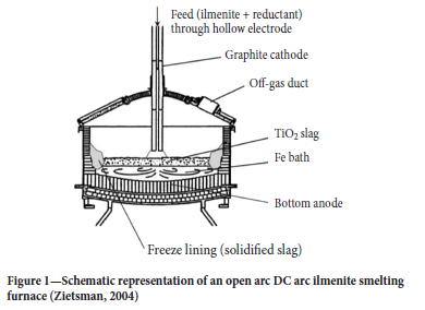
The fixed roof segments are made from steel and are refractory lined. The steel panels are water-cooled to avoid them melting. An off-gas duct extracts the furnace gas product and maintains a slightly positive pressure inside the furnace to avoid the presence of oxygen in the furnace freeboard space.
The sidewall is lined with a 98 mass % high-fired dense magnesium oxide refractory. The refractory is chosen to have some degree of thermal conductivity to allow for thermal energy transfer for freeze lining formation (Duncanson and Toth, 2004). A steel plate known as the inner shell surrounds the furnace. Between the inner shell and refractory brick, ramming material is placed to ensure sufficient contact between the refractory cold face and inner shell. Water is passed against the inner shell to remove thermal energy from the furnace. This cooling of the inner shell and consequent cooling of the refractory sidewall causes the molten slag in contact with the refractory hot face to solidify, thus forming the freeze lining.
Pistorius (2008) described two thermal non-equilibrium conditions inside the furnace. These arise due to the formation of the freeze lining and the temperature difference between the slag and metal.
Formation of the freeze lining
Ilmenite smelters operate with stringent limitations on the amount of impurities in the titania-rich slag product. Such limitations include less than 1.5 mass % Al2O3 and less than 1.2 mass % MgO in the slag (Pistorius, 2008). These requirements cause challenges for the integrity of the refractory lining and therefore the furnace structure. Owing to the low alumina and magnesia concentrations, the activities of these two species in the slag are low, thus making magnesia and high-alumina refractory bricks highly soluble in molten ilmenite slags. As a result, ilmenite slags are corrosive towards most known refractories (Zietsman, 2004). Ilmenite furnaces must therefore operate with a layer of frozen slag on the refractory hot face to protect the refractory.
Slag-metal temperature difference
The molten pig iron is 150°C colder than the slag phase. Pistorius (2008) postulated that partial solidification of the slag is expected at the slag-metal interface since the furnace slag operates at a low degree of superheat (<50°C) and thus slag should solidify when in contract with the colder pig iron. The effect of this departure from thermal equilibrium on furnace operation was further considered by Pistorius (2008). Pistorius et al. (2011) postulated that the slag in contact with the pig iron partially solidifies; first due to contact with the lower temperature pig iron, then by partial reduction of FeO in the slag immediately in contact with the pig iron bath by dissolved carbon in the pig iron bath via Equation [2], and finally by partial reduction of TiO2 in the slag to Ti2O3.
Since FeO fluxes the slag, the above reaction causes an increase in the liquidus temperature of the slag immediately in contact with the pig iron, causing the slag to solidify.
While there is no denying the evidence provided by Pistorius et al. (2011) of solidification of slag at the slag-metal interface through reduction of FeO in the slag by dissolved carbon in the pig iron, the primary solidification of the slag by purely coming into contact with a colder pig iron is a contentious issue. By this notion the pig-iron is always inherently at a lower temperature than the slag. The main cause of this temperature difference is an issue that has not been sufficiently explored. Lastly, the treatment of the ilmenite slag-pig iron interface is rarely considered in the open literature.
It is easy to test numerically whether a slag that is 150°C hotter than the pig iron will solidify at the slag-pig iron interface during operation. It is also easy to test numerically whether heating a furnace from bath temperatures below solidus temperatures will lead to a temperature difference of 150°C between the slag and pig iron. Thirdly, it is possible to calculate, using a heat transport model, the thickness of the frozen slag at the slag-pig iron interface.
The objectives of this paper are thus to investigate, using a finite element method (FEM) approach, a possible cause for the temperature difference between the slag and pig iron phase. Secondly to test perceived notions about the slag-pig iron interaction, and further to provide a methodology to numerically treat the slag-pig iron interaction. Such a method must yield a value for the thickness of the frozen slag at the interface. The model is applied to an idling furnace where the aim is to maintain the slag and pig iron at fixed temperatures, which in this study are taken to be 1578°C (slag with 15% FeO content) and 1428°C respectively. The operating temperature of the slag was chosen to be 30°C higher than its liquidus temperature, while the pig iron temperature was taken to be 150°C lower than the operating temperature of the slag.
Finite element model derivation
Numerical model geometry
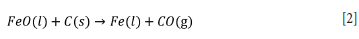
Due to lack of angular heat flow and symmetry along the central axial line in the furnace, the full 3D furnace structure will be modelled as a 2D structure as shown in Figure 2:
More detailed information about the dimensions of the furnace sidewall assembly is shown in Table I.
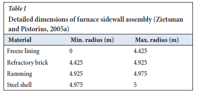
Figure 3 shows zones of the furnace to be modelled.
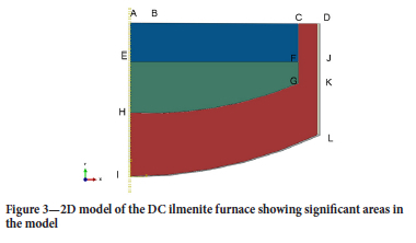
The major heat transport mechanisms that will be taken into account include (refer to Figure 3):
> Axial radiative and convective heat losses to the furnace freeboard space from the surface of the slag bath BC
> Radial sidewall heat losses to the sidewall cooling water on surface DJ
> Radial sidewall heat losses to sidewall cooling water on surface JK
> Axial heat losses from the slag bath to the pig iron via surface EF
> Axial hearth heat losses from surface IL
> Thermal energy from the electrode through surface AB (300 mm)
> Symmetry conditions are applied on AI.
Major heat sources and sinks that are taken into account include the crust formation on top of the slag bath due to radiation heat loss, solidification of slag in contact with the refractory sidewall to form the freeze lining, water cooling of the furnace sidewall, and losses through the hearth. The reduction reaction (Equation [1]) will not be taken into account because only idling furnace conditions (where feeding stops) are modelled. The chemical properties of the bath will be constant throughout the modelling period except for the slag and pig iron directly in contact with each other, where reduction of the slag by dissolved carbon in the pig iron takes place.
Axial radiative and convective heat losses
Axial radiative and convective heat losses on top of the slag bath (BC, Figure 3) will be accounted for by making use of an effective heat transfer coefficient (heff) on surface BC. The sink temperature for this radiative and convective heat loss is specified to be 25°C.
During furnace idle, feeding stops, resulting in no cloud of feed dust in the furnace freeboard zone. During operation this thick feed dust cloud helps to slow down radiative heat loss from the bath top (BC) to the furnace roof. When feeding stops the freeboard dust settles and thus increases the exposure of the roof refractory to radiative heat losses from the top of the slag bath. Added to the radiation heat loss are natural convective heat losses from the hot slag bath top to the cooler furnace roof panels (Reynolds, 2002).
Reynolds (2002) developed and applied a numerical model for radiative heat transport from the slag bath top to the freeboard space for three different open-bath systems - cobalt removal slags, ferronickel slags of lateritic origins, and zinc slag systems. According to this model, the slag radiates heat to the steel roof panels and upper furnace sidewalls. A portion of this radiation incident wave is reflected by the upper sidewall refractory and roof panel refractory back to the slag bath. The portion of this radiation heat loss that actually leaves the furnace freeboard space is controlled by the thermal resistance of the refractory wall that makes up the upper sidewall refractory and roof panels. Thus the effective heat transfer coefficient for the energy leaving the furnace via the furnace freeboard space is best approximated by making use of the thermal conductivity of the refractory lining the roof panels and its thickness:
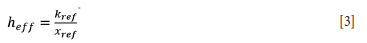
where heff (W.m-2.K-1) is the effective heat transfer coefficient (which includes radiative heat losses from the slag bath as well as convective heat losses), and kref (W.m-1.K-1) and xref (W.m-1.K-1) are the thermal conductivity and thickness of the refractory lining the steel roof panels.
This effective heat transfer coefficient is applied on the slag bath surface. However, the furnace freeboard space is larger than the slag bath top cross-sectional area (area AC), thus a correction has to be made to Equation [3] to account for the difference in area of the slag bath and freeboard space by multiplying the effective heat transfer coefficient by the ratio of furnace freeboard space area and slag bath area, given as 2 for industrial furnaces by Jones and Reynolds (2015). Jones and Reynolds (2015) reported that for a typical industrial furnace the value of the effective heat transfer coefficient is 12 W.m-2.K-1. Jones and Reynolds (2015) used freeboard refractory brick with a thermal conductivity of 1.5 W.m-1.K-1 and thickness of 0.25 m. For the current study, an effective heat transfer coefficient of 10 W.m-2).KA-1 is used. This corresponds to the lowest effective heat transfer coefficient found by Reynolds (2002). The sink temperature for this energy loss is taken to be that of process cooling water (25°C) running through the roof panels (Jones and Reynolds, 2015; Zietsman and Pistorius, 2005a, Reynolds 2002).
Thus the heat loss on surface AC is given by
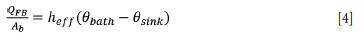
where Qfb is freeboard heat losses (W), Ab is the area of AC (61.51 m2)0bath is the temperature of the slag bath (1578°C), and 8si„k is the sink temperature (25°C).
Axial heat loss on surface CD are considered to be negligible and thus will not be taken into account. Surfaces CD will modelled as perfectly insulated surfaces (Zietsman and Pistorius 2005a).
Radial upper sidewall losses
Radial 'upper sidewall' heat losses will be accounted for by specifying a constant temperature of 50°C on the inner shell surface DJ (Figure 3).
Cooling water is passed against the inner shell (DJ), which is significantly colder then the slag bath. This causes heat to flow by convection from the slag bath (area ACFE) to the freeze lining. Heat then flows from the freeze lining by conduction to the refractory (area CDJF) and ramming, then through the inner shell, where it flows via convection to the cooling water. It has been argued by Zietsman (2004) that water cooling is not a rate-limiting factor in the sidewall heat loss process, thus the modelling of the convective heat loss to the water can be eliminated by specifying a boundary condition for the inner steel shell of 50°C on surface DJ.
The upper sidewall heat losses are thus given by (assuming no contact resistance between ramming and shell as well as ramming and refractory wall)
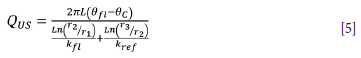
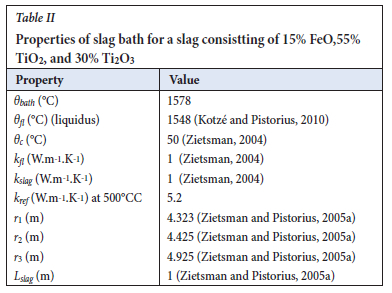
where Qus is the upper sidewall heat losses (W), L is the height of the slag bath (1 m), 0fl is the interface temperature between the freeze lining and slag bath, taken to be the liquidus temperature of the slag (1548°C). 8C is the temperature of the cooling water against the inner shell plate ( 50°C). r2 is the outer radial position of the freeze lining (4.43 m), r1 is the inner radial position of the freeze lining (4.32 m), kfl is the freeze lining thermal conductivity (1 W.m-1.K-1), r3 is the outer radial position of the refractory (4.93 m), and kref is the thermal conductivity of the refractory (5.2 W.m-1).K-1).
Radial lower sidewall losses
Radial lower sidewall heat losses will be accounted for by specifying a constant temperature of 50°C on the inner shell surface JK (Figure 3). The lower sidewall heat losses are given by
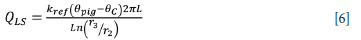
where Qls is the lower sidewall heat losses (W), 8pig is the operating temperature of the pig iron (1428°C). L is the height of the lower side wall (0.52 m), and r3 and r2 are the same as in Equation [6].
Hearth heat losses
Axial hearth heat losses will be accounted for by specifying a constant temperature of 50°C on surface IL.
The furnace shell in contact with the hearth bricks is air-cooled (Zietsman, 2004). Heat flows from the hot slag bath (area ACFE) via convection and conduction to the pig iron bath, from the pig iron bath (EFGH) via convection into the lower sidewall bricks and hearth bricks and then through the lower sidewall bricks and hearth bricks to the steel plate via conduction, followed by convection to the cooling media. Zietsman (2004) argued that the largest resistance to hearth heat losses is conduction through the refractory brick layer. As such, the dynamics of hearth heat losses can be fully captured even if the heat transfer to the cooling air is not captured in detail. Following this approach, a simple boundary of a constant temperature of 50°C on the hearth steel plate is used in this study. The heat loss to the hearth is given by
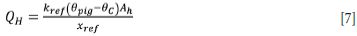
where Qh is the hearth heat losses (W), Ah is the area of the hearth (64.43m2), and xrf is the average thickness of the hearth brick (1.41 m).
Energy from the arc
Energy from the arc is accounted for by specifying a heat flux on surface AB (Figure 3). Thermal energy reaches the slag bath via four methods: (i) convection from the plasma as it passes over the slag surface, (ii) energy transport by electrons via the Thomson effect, (iii) condensation of electrons as they enter the slag surface, and (iv) radiation heat from the plasma (Qian Farouk, snf Mutharasan, 1995). All four methods are dominant directly underneath the electrode (at the centre of the furnace) and quickly become less effective within the radius of the electrode. However, radiation and convective heat transport continue to be effective at greater distances from the radius of the electrode. In the numerical model the surface of all heat transfer from the electrode is assumed to be equivalent to the electrode radius.
The heat flux (qEL) on surface AB can be calculated by summing the freeboard heat losses (Equation [4]), upper sidewall heat losses (Equation [5]), lower sidewall heat losses (Equation [6]), and hearth heat losses (Equation [7]) and dividing by the cross sectional area of the electrode:
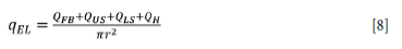
where qEL is the heat flux on surface AB and r is the radius of the electrode (0.3 m).
Heat movement within the slag bath and pig iron bath
Heat movement within the molten slag bath and pig iron bath is strongly influence by forced convection when the furnace is on, due to strong electromagnetic stirring of the bath caused by current flow through a self-induced magnetic flux in the slag and pig iron (Alexis et al., 2000). A further stirring of the slag bath is experienced due to momentum transfer from the arc jet as it impinges on the slag bath surface, causing shearing that opposes the electromagnetic stirring (Alexis et al., 2000).
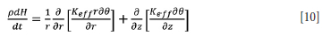
To model convective heat movement in both the slag and pig iron bath Equation [9] has to be solved. This requires that the velocity vector at each location and time step is known. This is found by coupling the energy balance with turbulent Navier-Stokes equations to calculate the velocity field at each time step. This adds five partial differential equations (PDEs) to the list of equations to be solved, in the case of 2D fluid flow where the standard k-e model is used. Furthermore, sources of momentum change have to be modelled by solving Maxwell's equations in the arc region and bath region. This enables the calculation of electromagnetic forces on each fluid element and thrust of the arc on the slag bath. This adds a further four PDEs to be solved. This can be computationally expensive in terms of both processing time and resources.
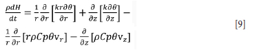
where p is the density of the phase considered, H is enthalpy, r is the radial dimension, k is the thermal conductivity of the phase being considered, which can take the value of turbulent thermal conductivity in turbulent regime, Cp is heat capacity, 0 is temperature, vr is the radial velocity component, vz the axial velocity component, and t is time.
To overcome the need to couple the temperature field with the velocity flow field, an effective thermal conductivity can be used to account for natural and forced convection in the slag and pig iron bath at temperatures above their liquidus (Vanaparthy and Srinivasan, 1998). In this approach, an inflated thermal conductivity of the liquid phase - known as effective thermal conductivity - is used in a conductive energy balance equation at temperatures above the liquidus of the material being modelled. At temperatures below the liquidus, the molecular thermal conductivity of the slag and pig iron is used. By taking this approach, Equation [9], in the case of a molten bath, is transformed to
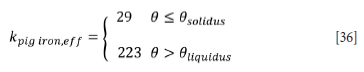
where Keff is the effective thermal conductivity, which takes the value of
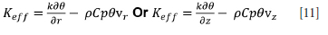
The inflation of the molecular thermal conductivity of the molten phases takes the form (Oksman et al., 2014):
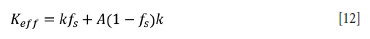
where Keff is the effective thermal conductivity of either the motlen slag or pig iron, k is the molecular thermal conductivity of slag or pig iron, f is the solid fraction of either slag or pig iron, and A is the multiplier used to inflate the molecular thermal conductivity of a molten phase.
In this form, it is assumed that the molecular thermal conductivity of the solid phase is the same as that of the molten phase. This approach can be taken since the value of A can change to accommodate any value assumed for the thermal conductivity of the molten phase.
The multiplier A has been assigned rather arbitrarily; Zietsman (2004) used a value of 5 for his work in modelling ilmenite freeze lining growth and depletion for the same furnace size as used in this study. Whether this value is valid for representing convective heat transfer of the furnace could not be said due to nondisclosure agreements between Zietsman (2004) and the corporate collaborator.
One method to compute the effective thermal conductivity is to set the energy lost by the bath to be equal to the energy gained by the sidewall assembly. Assuming thermal contact resistance is negligible and that the thermal resistance of the ramming phase, steel, and cooling medium is negligible, Equation [13] is derived.
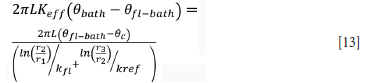
where Keff is the effective thermal conductivity of the bath, 0bath is the bath temperature, 0fl-bath is the temperature of the bath-freeze lining interface, r1 is the radial position of the bath-freeze lining interface, r2 is the radial position of the inner refractory face, kfl is the freeze lining thermal conductivity, and r3 is the radial position of the outer face of the refractory wall.
In Equation [13], the ratio  may be taken as the average heat transfer coefficient of the furnace (Harrison, 1981). Thus it can be compared to reported values for industrial DC arc furnaces. Solving for Keff yields
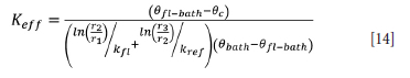
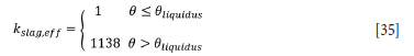
Using data from Zietsman (2004) for a slag bath with a composition of 15% FeO, 55% TiO2, and 30% Ti2O3 at a bath temperature of 30°C above its liquidus temperature with the operating parameters shown in Table II, the average heat transfer coefficient,  can be calculated to be 263 W.m-2.K-1. This value is in agreement with the heat transfer coefficient for industrial slags reported by Jones and Reynolds (2015) of 200 WW.m-2.K-1. keeff was computed to be 1138 W.m-1.K-1.
When the furnace is off, the average heat flux,  , is expected to be much less than 263 W.m-2.K-i)as natural convection will dominate, not forced convection.
The same calculation can be done for the pig iron bath by equating the bath heat losses to the sidewall heat losses to find keff when the furnace is on, using data in Table III. For this calculation it can be assumed that the pig iron 'freeze lining' does not add resistance to lower sidewall heat losses.
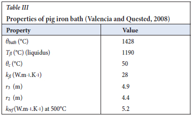
Using the above method it was found that the effective thermal conductivity of the molten pig iron is 223 W.m-1.K-1 when the furnace is on. Since the effective thermal conductivity is a representation of both molecular conduction and convective heat flow, it can be said the slag is more stirred that the pig ion bath.
With the above taken into account, the energy balance to be solved over the furnace body, area ADLI, is of the conductive heat model type (Equation [15].
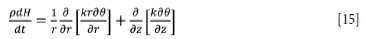
where k is the thermal conductivity of the material in the region of calculation, which takes the value of effective thermal conductivity in the case of molten slag and pig iron. H is the specific enthalpy of the region of calculation given by:

where Cp(0) is the heat capacity of the region of calculation. In particular for the slag and pig iron, an adjusted heat capacity will be used to account for latent heat of fusion:
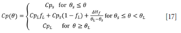
where Cps is the heat capacity of solid slag or pig iron, CpL is the heat capacity of liquid slag or pig iron, depending on the region of calculation0s is the solidus temperature, 0L the liquidus temperature, AHf is the latent heat of fusion, and fL is the liquid fraction.
FEM implementation of heat transport models
Strong form of governing equations
Abaqus 2017 was used as a modelling tool to resolve Equation [16] over the domain of the furnace inclusive of freeze lining, furnace sidewall, ramming, hearth, and steel shell. To accomplish this, boundary conditions have to be prescribed:
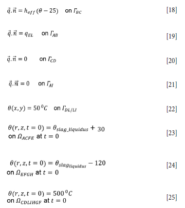
where q is the heat flux (W.m-2), heff is the effective heat transfer coefficient (W.m-2.K-1), and 8 is temperature (K).
Temperatures defined by Equations [23-25] are used only at the beginning of the simulation. Equation [23] specifies a slag operating 30°C above its liquidus temperature, while Equation [24] specifies a pig iron bath that is at 150°C lower that the slag phase. Equation [25] specifies the temperature of the refractory brick at the beginning of the calculation step.
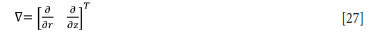
Equation [15] can be written in matrix form as follows:
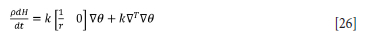
where V is a gradient matrix given by:
Weak forms of governing equations
The weak form of Equation [26] combined with the boundary conditions (Equations [18-15] is:
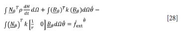
where N0 is the global shape function matrix containing the interpolation functions of temperature, p is density, Ω is the domain of the furnace as shown in Figure 3, 0 is the column matrix containing the global nodal values of temperature. β0 contains derivatives of the shape function, and fext0 is a column matrix containing normal components of the heat flux vector on the boundaries of the furnace, given by:
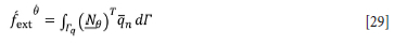
where qn is the normal component of the heat flux vector on natural boundaries.
Surface interactions
The slag has been shown to penetrate the magnesia bricka up to 15 mm behind the slag-refractory interface (Garbers-Craig and Pistorius, 2006). Due to this intimate interaction between the refractory and the slag, little thermal contact resistance is expected between the two phases. An estimate of 2 x10⁴ W.m-2.K-1 was used for the thermal contact conductance between the slag and refractory.
Graphite ramming is installed between the outer refractory wall and the steel shell. Ramming material ensures that no air gaps form between the steel shell and the furnace refractory so as to ensure sufficient thermal contact between these two materials (Zietsman and Pistorius 2005a). Given this, it is expected that the thermal contact resistance will be small between the refractory wall and the ramming and between the ramming and steel shell. An estimate of 2 x10⁴ W.K-1 was used for the thermal contact conductance between refractory-ramming and ramming-steel contact pairs. The same thermal contact conductance was used for the pig iron-refractory interaction.
The slag-pig iron interaction is the focus of the study. Initially a value of 2 x10⁴ W.m-2).K-1 is used for the slag-pig iron contact pair.
Material properties
Slag
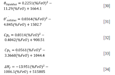
Typical ilmenite slag consists of 54% TiO2 34% Ti2O3, and 10% FeO, the balance being minor impurities (Garbers-Craig and Pistorius, 2006). The solidus and liquidus temperatures as well as the heat of fusion of the slag depend on the slag chemistry, as shown by Kotzé and Pistorius (2010). Linear approximations of the liquidus temperature, solidus temperature, slag heat capacity, and heat of fusion were determined by Kotzé and Pistorius (2010) based on FactSage-predicted thermodynamic data for a range of slags containing from 6.8% to 17.98% FeO (Equations [30-34]). From this data Kotzé and Pistorius (2010) were able to determine the thermodynamic properties of ilmenite slags as a function of iron oxide content. The following expressions were calculated for the slag compositions used:
The slag used in this study contains 15% FeO. The thermal conductivity of the slag bath was specified as follows when the furnace was on:
The density of the slag was 3.800x10³ kg.m-3 (Zietsman, 2004). The heat capacity was specified according to Equation [17].
Pig iron
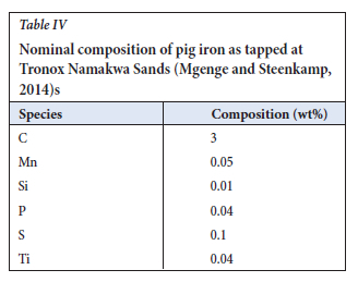
The pig iron phase is rich in iron and contains 2% carbon with small amounts of silicon, manganese, and phosphorus (Zietsman, 2004). A higher carbon content of 2.5% has been reported by Gous (2006) and an even higher value of 3% by Mgenge and Steenkamp (2014). A nominal grade of pig iron is given by Mgenge and Steenkamp (2014) and is reported in Table IV:
In this study, properties of grey cast iron were used to model the pig iron phase. In other studies the properties of molten iron have been quoted for the thermal properties of pig iron. The thermal conductivity of the pig iron was adjusted similar to the slag bath.
The heat capacity of pig iron was specified as follows (Valencia and Quested, 2008):

The heat of fusion was specified as 240x103 J.kg-1 (Valencia and Quested, 2008). The bulk density was specified as 7.2x10³ kg.m-3 (Zietsman and Pistorius, 2005b).
Ramming
For this study a pre-compacted high-graphite (80% w/w) in a coal tar binder (20% w/w) rammable was used. Its heat capacity is 700 J.kg-1).K-1, thermal conductivity 25 W.m-1 K-1, and density 1.33 kg.m-3 (Brulin et al., 2011).
Refractory
The furnace has a range of zone-specific refractories. For most part the furnace is lined with high-fired dense magnesium brick, which has a specific heat capacity of 800 J.kg-1.K-1 and a thermal conductivity of
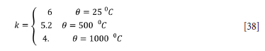
(Valencia and Quested, 2008). The bulk density of the refractory is 2.787x10³ kg.m-3.
Steel shell
The furnace structure is held intact by a steel shell that surrounds the refractory and hearth. A lot of mention is made of this shell (Pistorius, 2008; Zietsman, 2004; Coetzee et al., 2007); however, very little is said about the type of steel that is used. Zietsman (2004) quotes a carbon content of 1.2 wt%, and a manganese content of 0.3%, which suggests that the shell is of ultra-high-carbon steel.
The heat capacity of steel was taken as 461 J.kg-1.K-1. The thermal conductivity is taken as 51.9 Wm-1.K-1, and density 7870 kg.m-3.
Results
Contacting a hot slag with a colder pig iron
In this scenario a slag at 1578°C is contacted with a pig iron at 1428°C. The slag temperature is chosen to be 30°C above the liquidus (1548°C for a slag with 15% FeO) (Equation [30]) while the pig iron temperature is chosen to be 150°C lower than the slag. The furnace is kept in idling mode by only supplying the power needed to sustain the slag and pig iron temperatures (1.7 MW) given the heat losses (Equations [3-6]). The interface between the slag and pig iron is modelled as perfectly permeable to heat transfer by specifying a thermal contact conductance of 2 x10⁴ W.m-2.K-1. The objective of this test is to observe whether the slag at the slag-pig iron interface will solidify by just coming into contact with a colder pig iron, as stated by Pistorius et al. (2011), and also to observe whether the slag-pig iron temperature difference will be maintained throughout the calculation time.
Figure 4 shows the volume-weighted average temperature of the slag bath and pig iron bath after they have been brought into contact inside the furnace. Evidently, the temperature difference of 150°C is not sustained after contact; instead, the slag loses its thermal energy to the pig iron bath and the temperatures converge. This is evidence of the strong agitation of the slag bath and pig iron bath inside the furnace, captured here by the use of effective thermal conductivity of the slag and pig iron at temperatures above their respective liquidus temperatures. The reason the slag bath temperature is lower than that of the pig iron is because of the low temperature of the slag behind the freeze lining, which lowers the volume average temperature. Discarding the freeze lining from the slag average temperature gives a slag temperature of 1584°C, which compares much better to the 1579°C average temperature of the pig iron. Thus there is a 5°C temperature difference between the slag bath and pig iron bath when the two are brought together, not 150°C as quoted in the literature. Thus heat transport alone cannot explain the 150°C temperature difference between the slag bath and pig iron bath quoted for industrial furnaces.
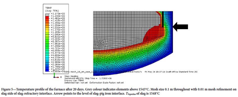
Figure 5 shows the temperature profile inside the furnace after 20 days of cantact between hot slag and colder pig iron. A 20-day period was chosen to ensure thermal equilibrium was reached. Elements with temperatures higher than 1543°C are coloured grey while those lower than 1543°C are colour-coded as per the legend. A constant power supply of 1.7 MW was maintained throughout to compensate for heat losses.
From Figure 5 it can be seen that at the slag-metal interface (indicated by the arrow) there is no sheet of elements with a temperature lower than 1548°C, the liquidus temperature of 15% FeO slag (see Equation [30]), as predicted by Pistorius et al. (2011). The 150°C difference between the slag bath and pig iron bath simply dissipates to the pig iron bath and energy from the electrode passes unhindered through the slag phase to the pig iron phase. This provides proof that solidification of slag at the slag-pig iron interface does not begin at the interface since purely from a thermal point of view any temperature difference between the slag and pig iron bath is dissipated between the two phases.
Also, the freeze lining in Figure 5 is much thicker than the 0.1 m in accordance with Equation [40]; this is because of the near-unhindered heat flow from the slag bath to the pig iron bath, which allows a thicker freeze lining to grow.
To maintain the 150°C difference between the slag and the pig iron it would seem that a 'barrier' to heat movement from the slag phase to the pig iron is needed. An ideal candidate for this barrier is solid slag at the interface, since solid slag has a low thermal conductivity of 1 W.m-1.K-1. This barrier is postulated to initially be in the form of co-current laminar flow of slag with the pig iron phase close to the furnace walls. This slag is only transformed to solid slag through reduction reactions close to the furnace walls.
Electromagnetically induced flow causes thorough countercurrent flow in both the slag bath and pig iron bath directly under the electrode. Away from the electrode, the slag and pig iron may flow in a laminar co-current pattern, giving enough time for the slag and pig iron to exchange thermal energy; without, however, the slag solidifying (as seen in Figures 4 and 5). During this interaction carbon in the pig iron reduces the slag, forming solid slag at the interface. In this scenario a slag fluid element remains in close contact with the pig iron due to a slow co-current flow near the outer wall of the furnace. The assumption that the slag solidifies at the slag-pig iron interface purely by coming into contact with a colder pig iron is nullified; furthermore, a method by which an intimate contact between the slag and pig iron can arise is provided, which is slow co-current flow close to the furnace walls.
Proof of concept is seen in results by Pistorius et al. (2011), which show that the reduction product concentration increases towards the furnace wall and decreases directly under the electrode. This constitutes evidence of reduced contact time between the slag and pig iron in this high-mobility zone. Further proof can be seen in flow patterns within a DC arc furnace (Harada et al., 2018).
Numerical accounting for solid slag at slag-pig iron interface
From Figure 5 it can be seen that just contacting a hot slag with a colder pig iron does not result in a 150°C temperature difference between the slag and pig iron bath. The question is; how does one numerically account for the heat transport barrier posed by the solid slag at the slag-pig iron interface?
One way to do this is by interposing a low thermal contact conductance between the slag bath and the pig iron bath. All the heat lost through the pig iron via the lower sidewall (QLs) and hearth heat losses (Qh) is derived from the slag, such that the heat lost by the slag to the pig iron is given by
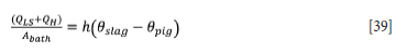
where Abath is the cross-sectional area of the bath (61.5 m2), h is the thermal contact conductance between the slag and pig iron, 0slag is the slag bath temperature (1578°C), and 0pig is the pig iron bath temperature (1428°C). From Equation [39] the thermal contact conductance needed to maintain a slag that is 150°C hotter than the pig iron can be calculated to be 59.3 W.m-2.K-1. If this thermal contact conductance is taken to be a representation of solid slag at the interface, then its value is given by
where kslag is the thermal conductivity of the slag (1 W.m1 K-1) and xslag is the thickness of the solid slag. Since xslag is the only unknown, its value can be calculated to give 1.7 cm, thus yielding a value for the thickness of the solid slag. If higher values of the solid slag's molecular thermal conductivity, such as 3 W.m-1 K-1, are used, a thicker solid slag layer of 5 cm results. At this stage it is not clear what governs this thickness, since this solid layer does not form by heat transport alone.
The same test of contacting a slag at 1578°C with a pig iron at 1428°C can be done to see if the temperature difference between the slag and pig iron will be maintained throughout the calculation time-frame when a thermal barrier in the form of a low thermal contact conductance is used (59.3 W.m-2.K-1) between the slag and pig iron. The low thermal contact conductance is applied throughout the slag-pig iron interface to resemble a solid slag layer throughout the bath in accordance with sounding observations.
Figure 6 shows the volume-weighted average temperature of the slag and pig iron bath from the time of contact to 20 days after contact. It is clear that the temperature difference of 150°C is maintained. This validates the use of a decreased thermal contact conductance to model the presence of solid slag at the slag-pig iron interface.
Figure 7 shows the temperature profile of the furnace after 20 days. Cells with temperatures above 1543°C are coloured grey, while those lower are colour-coded as per the legend. Evidently there is a temperature difference between the slag and pig iron after a thermal barrier is interposed. Furthermore, there is a 11 cm (minimum) thick freeze lining in accordance with Equation [40]. This adds evidence to the conjecture that the temperature difference between the slag and pig iron is due to the solid slag at the interface, and not the other way around. That is, the solid slag must exist first before the pig iron temperature can be lower than the slag temperature. If the solid slag was not present there would not be a temperature difference between the slag bath and pig iron bath.
Conclusions and recommendations
A finite element method (FEM) model was developed making use of an effective thermal conductivity to model convective heat flow in the slag and pig iron baths in an ilmenite smelting furnace. The model was used to test the notion that the slag solidifies at the slag-pig iron interface because of the slag coming to contact with a colder pig iron. The model was used to establish and quantify the cause for the temperature difference between the slag and pig iron. A methodology to treat the slag-pig iron interface when using a FEM model was developed and a new slag solidification mechanism at the slag-pig iron interface is suggested.
It was found that contacting a hot slag with a colder pig iron while the furnace is running does not lead to slag solidification at the slag-pig iron interface. Furthermore, the temperature difference between the slag and pig iron is not maintained unless there is a thermal barrier between the slag and pig iron. The thermal barrier must exist first in order for the slag and pig iron temperatures to differ. This thermal barrier is postulated to initially be in the form of a slow co-current flow of slag and pig iron in the outer parts of the furnace. This flow provides enough time for the carbon in the pig iron to reduce the slag immediately in contact with it. Directly under the electrode, the fast-moving countercurrent flow of the slag and pig iron does not allow enough time for the reduction reaction to take place, hence the decrease in reduction products in that region and possibly no solid slag forms. This approach negates the need to have the pig iron bath inherently colder than the slag bath as previously thought, and thus the need for the slag to first solidify at the interface by purely coming into contact with an inherently cold pig iron. The thickness of the solid slag at the interface was calculated to be 1.7 cm for the conditions and furnace dimensions investigated.
The method of using a low thermal contact conductance for the slag-pig iron pair was found to sufficiently account for the presence of solid slag at the slag-pig iron interface, leading to a temperature difference between the slag and pig iron bath and consequently the correct freeze lining thickness.
References
Alexis, J., Ramirez, M., Trapaga, G,. and JoNssoN, P. 2000. Modelling of a DC electric arc furnace - Heat transfer from the arc. ISIJ International, vol. 40, no. 11. pp. 1089-1097. [ Links ]
Bessinger, D. 2000. Cooling characteristics of high titania slags. MSc dissertation, University of Pretoria. [ Links ]
Brulin, J, Rekik, A., Josserand, I., Blond, E., Gasser, A., and Roület, F. 2011. Characterization and modelling of a carbon ramming mix used in high-temperature industry. International Journal of Solids and Structures, vol. 48, no. 5. pp. 854-864. [ Links ]
Coetzee, C., Lamont, P.H., Bessinger, D., Rabe, J., Zietsman, J.H., and Muller, J. 2007. Application of UCAR* Chill KoteTM lining to ilmenite smelting. Proceedings of the 11th International Ferroalloys Congress, New Delhi, 17-21 February 2007. Indian Ferro Alloy Producers Association. pp. 837-846. https://www.pyrometallurgy.co.za/InfaconXI/837-Coetzee.pdf [ Links ]
Duncanson, P.L. and Toth, J.D. 2004. The truth and myths of freeze lining technology for submerged arc furnaces. Proceedings of the Tenth International Ferroalloy Congress, Cape Town, 1-4 February 2004. Southern African Institute of Mining and Metallurgy, Johannesburg. pp. 488-499. [ Links ]
Garbers-Craig, A.M. and Pistorius, P.C. 2006. Slag-refractory Interactions during the smelting of Ilmenite. South African Journal of Science, vol. 102. pp. 575-580. [ Links ]
Gous, M. 2006. An overview of the Namakwa Sands ilmenite smelting operations. Journal of the Southern African Institute of Mining and Metallurgy, vol. 106. pp. 379-383. [ Links ]
Harada, T., Hirata, T., Toh, T., and Yamada, T. 2018. Characteristics of closed type DC arc furnace for molten slag reduction (Development of moltern slag reduction process -1). ISIJ International, vol. 58. pp. 1-9. [ Links ]
Harrison, C.E. 1981. Heat transfer and convection in liquid metals. MSc thesis, University of British Columbia. [ Links ]
Jones, R.T. and Reynolds, Q.C. 2015. Design methods for DC arc furnace to enhance furnace integrity. Proceedings of the 54th Conference of Metallurgist, Toronto, 23-26 August 2015. Canadian Institute of Mining, Metallurgy and Petroleum, Montreal. 10 pp. https://www.pyrometallurgy.co.za/Mintek/Files/2015Jones-Intensity.pdf [ Links ]
Kotzé, H. and Pistorius, P.C. 2010. A heat transfer model for high titania slag blocks. Journal of the Southern African Institute of Mining and Metallurgy, vol. 110. pp. 57-66. [ Links ]
Mgenge, S.G. and Steenkamp, J.D. 2014. Furnace tapping practice at Tronox Namakwa Sands. Proceedings of the Furnace Tapping Conference 2014, 27-29 May 2014. Hundermark, R. and Steenkamp, R. (eds). Symposium Series S80. Southern African Institute of Mining and Metallurgy, Johannesburg. pp. 137-146. [ Links ]
Oksman, P., YU, S., Kytönen, H., and Louhenkilpi, S. 2014. The effective thermal conductivity method in continuous casting of steel. Acta Polytechnica Hungarica, vol. 11, no. 9. pp. 5-22. [ Links ]
Pistorius, P.C. 2008. Ilmenite smelting: The basics. Journal of the Southern African Institute of Mining and Metallurgy, vol. 108.- pp. 35-43. [ Links ]
Pistorius, P.C., DeVilliers, J.P.R., Gràser, P., and Venter, A. 2011. Partial slag solidification within an ilmenite smelter. Mineral Processing and Extractive Metallurgy, vol. 120, no. 4. pp. 211-217. [ Links ]
Qian, F., Farouk, B., and Mutharasan, R. 1995. Modelling of fluid flow and heat transfer in the plasma region of the DC electric arc furnace. Metallurgical and Materials Transactions B, vol. 26(B). pp. 1057-1067. [ Links ]
Reynolds, Q.C. 2002. Thermal radiation modelling of DC smelting furnace freeboards. Mineral Engineering, vol. 15. pp. 993-1000. [ Links ]
Valencia, J.J. and Quested, P.N. 2008. Thermophysical Properties. Handbook 22B. Furrer, D.U. and Semiatin, S,L, (eds). American Society for Metals. pp. 468-481. https://doi.org/10.31399/asm.hb.v22b.a0005523 [ Links ]
Vanaparthy, N.M. and Srinivasan, M.N., 1998. Modelling of solidification structure of continuous cast steel. Modelling and Simulation in Material Science and Engineering, vol. 1, no. 6. pp. 237-249. [ Links ]
Zietsman, J.H. 2004. Interaction between freeze lining and slag bath in ilmenite smelting. PhD thesis, University of Pretoria. [ Links ]
Zietsman, J.H. and Pistorius, P.C. 2005a. Modelling of an ilmenite-smelting DC arc furnace process. Mineral Engineering, vol. 19, pp. 1-18. [ Links ]
Zietsman, J.H. and Pistorius, P.C. 2005b. Ilmenite smelter freeze lining monitoring by thermocouple measurements: Model results. Proceedings of Heavy Minerals 2005, Ponte Vedra, FL,16-19 October 2005. Society for Mining, Metallurgy & Exploration, Englewood, CO. pp. 221-228. [ Links ]
 Correspondence:
A. Mabentsela
Email: arthurmabentsele@gmail.com
Received: 9 Jun. 2020
Revised: 28 Sep. 2020
Accepted: 20 Oct. 2020
Published: March 2023

