


Services on Demand
Article
 English (pdf)
 Article in xml format
 Article references
Indicators

Related links
-
 Cited by Google
 -
 Similars in Google
Share

 Permalink
Journal of the Southern African Institute of Mining and Metallurgy
On-line version ISSN 2411-9717
Print version ISSN 2225-6253
J. S. Afr. Inst. Min. Metall. vol.123 n.1 Johannesburg Jan. 2023
http://dx.doi.org/10.17159/2411-9717/1248/2023
PROFESSIONAL TECHNICAL AND SCIENTIFIC PAPERS
Elastic damage characterization of an ilmenite smelter freeze lining
A. Mabentsela
University of Botswana, Minerals Engineering, Department of Civil Engineering, Gaborone
SYNOPSIS
A furnace freeze lining is necessary for safety and economic reasons in several smelting operations. The integrity of the freeze lining is put at risk by furnace power imbalances. Although numerous models have been derived to model the growth and depletion of the freeze lining due to power imbalances, no model exists for thermomechanical damage to the freeze lining.
This study provides an initial pathway for modelling thermomechanical damage to the freeze lining in an ilmenite smelting furnace using information from the literature and experimental work.
A methodology under the framework of continuum damage mechanics is proposed to model mechanical damage to the freeze lining due to phase changes, thermophysical changes, and constrained thermal expansion. Drill cores of solidified slag ingots were used to represent the freeze lining. The modified power law proved to be the best predictor of the softening response of the drill cores. Damage driving parameters were extracted from the raw data, and governing equations of the parameters with respect to temperature were derived for use in a finite element method (FEM) code.
Keywords: ilmenite smelting, freeze lining damage, elastic damage, thermal damage.
Introduction
Freeze lining technology has made it possible for high-temperature, high-agitation, and unstable refractory-slag systems to be usEd with minimal impact on the refractory integrity. A furnace freeze lining is the term given to frozen furnace material which accumulates on the hot side of the refractory face due to cooling on the refractory cold face. The presence of a freeze lining limits the interaction between molten slag and the refractory hot face by providing a barrier to molten slag-refractory contact. The freeze lining therefore protects the refractory and thereby prolongs the furnace life.
A freeze lining is a necessity for safety and economic reasons in some smelting operations. Operations that have been made viable by freeze lining technology include the Hall-Héroult process, in which without the freeze lining the refractory would fail in six months (Crivits 2016), ilmenite smelting, which targets a refractory lifespan of ten years through the freeze lining application (Zietsman, 2004), and the ISASMELT process, which aims to increase refractory lifespan which otherwise is challenged by the high temperatures of the process (Verscheure et al., 2005).
Much has been published about the thermal aspects of growth and depletion of the freeze lining. These works have been summarized by Crivits (2016). Similarly, attention has been given to thermochemical models for freeze lining growth and depletion. Zietsman (2004) derived a finite difference method (FDM) model coupled with FactSage® to calculate freeze lining thickness and composition variations in response to changes in furnace power, the slag bath, and feed. Thermal mass transfer models have also been produced for various smelting industries (Crivits, 2016). Attention has been given to the physical aspects of freeze lining growth through the use of a cold probe technique. Fallah-Mehrjardi, Hayes, and Jak (2014) studied the effect of bath chemistry on the freeze lining microstructure of a copper smelting slag at the laboratory scale using the cold probe technique and found that the freeze lining formed depended on the viscosity of the slag bath. Kalliala et al. (2015) also used the cold probe technique in a refractory sleeve to show that the freeze lining composition depends on the cooling rate of the freeze lining during formation.
Little work has been done to model the thermomechanical aspects of freeze linings, despite several comments on aspects that mechanically challenge the freeze line integrity (Kalliala et al., 2015; Crivits, 2016; Zietsman, 2004). A thermomechanical model was produced by Campbell, Pericleous, and Gross (2002) that made use of a computational fluid mechanics (CFD) model coupled with a thermomechanical module to model the penetration, corrosion, and erosion of the refractory in a HIsmelt process. However, this model is for the refractory, not for the freeze lining.
The purpose of this paper is to provide an initial pathway through a literature search and experimental methods for thermomechanical modelling of furnace freeze linings, and to extract from the experimental results the relationship between important parameters as a function of temperature needed for finite element method (FEM) modelling of freeze lining fracture due to thermomechanical effects. The work is applied to the ilmenite smelting process.
Literature review
Ilmenite smelting and freeze linings
Ilmenite smelting involves the carbothemic reduction of ilmenite to give a titanium dioxide-rich slag (the primary product) and a pig iron by-product. The reduction takes place in the liquid phase at a slag temperature of approximately 1650°C (Pistorius, 2008).
Ilmenite smelters operate with stringent limitations on the amount of impurities present in the titania-rich slag product. Such limitations include less than 1.5% (mass percentage) Al2O3 and less than 1.2% MgO in the slag (Pistorius, 2008). These requirements cause challenges for the integrity of the furnace structure as far as the furnace refractory is concerned. Due to the low alumina and magnesia concentrations in the slag, the activity of these two species is low, thus making magnesia and high-alumina refractory bricks highly soluble in molten ilmenite slags. Alumina refractories are even more challenged because they form a liquid at the operating temperature of the furnace. Magnesia bricks are therefore the only viable refractory (Garbers-Graig and Pistorius, 2006). To protect the magnesia refractory bricks from molten slag, ilmenite furnaces mus operate with a freeze lining.
Ilmenite slag baths typically contains TiO2, Ti2O3, and FeO with minor impurities, mainly SiO2, MnO, AkO3, MgO, V2O3, CaO, and Q2O3 (Garbers-Graig and Pistorius, 2006). Figure 1 shows across-section through a TiO2-FeO-Ti2O3 ternary phase diagram at10% FeO, a typical FeO content in ilmenite slags, as predicted by the thermochemical package FactSage 5.2. Figure 1 serves to show that the TiO2-FeO-Ti2O3 system has a eutectic point; point (A). Slags with a TiO2 content higher than the eutectic composition deposit rutile as the main freeze lining constituent, while slags with a TiO2 content lower than the eutectic point composition but higher than the M3O5 composition deposit pseudobrookite as the main freeze lining constituent (Zietsman, 2004).
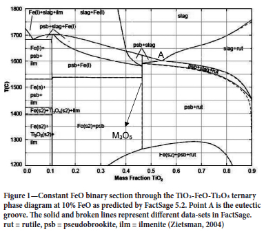
A typical ilmenite slag consists of 54% TiO2, 34% Ti2O3, and 10% FeO, the balance being minor impurities (Garbers-Graig and Pistorius, 2006). This composition lies on the eutectic point therefore the expected freeze lining composition is pseudobrookite and rutile (see Figure 1). Moreover, at temperatures lower that 1300°C; near the refractory hot face, the freeze lining is expected to contain iron as a standalone phase. Pseudobrookite is a solid solution consisting of M2+(Ti4+)2O5 and (M3+)2Ti4+O5, where M2+ is Fe2+, Mg2+, and Mn2+ while M3+ is Ti3+, Cr3+, Al3+, and V3+ (Garbers-Graig and Pistorius, 2006).
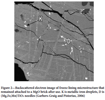
While the bulk of the freeze lining consists of pseudobrookite, rutile, and iron globules, the freeze lining attached to the refractory has a different composition; that of the reaction products of the refractory and slag. The products consist of (Mg,Fe,Mn)TiO3 needles embedded in a high-TiO2-MgO matrix with composition 56% TiO2 and 41% MgO, with the remainder being (Mn,Fe)O (Garbers-Graig and Pistorius 2006). Importantly, the (Mg,Fe,Mn) TiO3 needle phase does not have any preferential orientation (see Figure 2), hence the freeze lining at the micro-level does not have any directional weakness and may be treated as an isotropic material.
Ilmenite freeze lining behaviour
It is known that solid ilmenite slags undergo significant compositional changes during temperature changes and in oxygen-rich environments such as air. Importantly, these compositional changes affect the mechanical behaviour of the solid slags, rendering them mechanically weak. Furthermore, the pseudobrookite crystals undergo irregular expansion during temperature changes (de Villiers, Göske, and Tuling, 2005). These changes may also apply to the freeze lining during furnace cooling cycles when the freeze lining is exposed to oxidizing conditions in the furnace freeboard space due to ingress of air when the furnace pressure control is off and the slag has been drained below the freeze lining height. No numerical approach has been used to capture the mechanical consequence of these changes.
Modelling work by the author, based on a finite element method (FEM), on a 5 m radius DC ilmenite furnace at steady state in idle mode showed that the steady-state temperature of the freeze lining directly in contact with the refractory is approximately 760°C. The solidus temperature of the slag which forms the freeze lining is approximately 1458°C, depending on the iron content (Kotzé and Pistorius, 2010). Thus the highest temperature that the freeze lining experiences is approximately 1458°C, while the lowest temperature is dictated by the length of the stoppage and position in relation to the refractory wall.
Irregular expansion of pseudobrookite crystals during temperature changes
De Villiers, Göske, and Tuling (2005) studied the thermal straining of M3O5 crystals during temperature changes and oxidation. They found that the pseudobrookite unit cell undergoes irregular strains during temperature changes; on heating the a-axis contracts slightly, the b-axis expands slightly, while the c-axis expands significantly over a temperature range of 50-220°C. The authors noted cracking of the pseudobrookite crystals upon heating due to lattice strain.
From work by Stana (2016) the coefficient of thermal expansion of titanium dioxide slags is approximately 40 x10-6 °C-1 for a temperature range of 125-525°C, and 30 x 10-6 °C-1 for 625-700°C. In comparison, the coefficient of thermal expansion of MgO refractory is in the region of 13.6 x 10⁻⁶ -14.7 x 10 °C-1 for the temperature range of 20-1765°C (Heindl, 1933). The coefficient of thermal expansion of titania-rich slag is thus close to 2.7 times that of the magnesium oxide refractory. The coefficient of thermal expansion of an ilmenite freeze lining is expected to be close to that of titania-rich slags. The difference in thermal expansion between the refractory brick and freeze lining is bound to cause a mechanical load at the freeze lining-refractory interface, especially if the temperature change at the interface is significant, e.g., during a long stoppage and subsequent recovery of power.
Rutile-anatase phase change
Rutile undergoes a transition to form anatase at temperatures between 400 and 1000°C (Bessinger, 2000). This results in a molar volume increase of 8.47% (Bessinger, 2000). This volume increase can add a localized compressive stress to the already present thermal compressive stresses experienced by the freeze lining during transient temperature conditions.
Disproportionation reactions and oxidation
It is known that the pseudobrookite phase is not stable in near-ambient and oxygen-rich environments similar to those that exist when the furnace is off. Pseudobrookite decomposes in two ways; disproportionation reaction and oxidation reaction (Pistorius, 2008). The oxidation reaction is accompanied by spontaneous crumbling of slag ingots and possibly furnace freeze linings.
Disproportionation reaction involves FeO and T12O3 in the pseudobrookite phase (Equation [1]). This reaction is possible at temperatures lower than 1100°C and is triggered by oxidation (Pistorius, 2008):

Equation [1] results in a 0.75% molar volume increase (Bessinger, 2000), which could add to the compressive stress that the freeze lining experiences during transient conditions.
The oxidation reaction is linked to the oxidation of pseudobrookite to form M6O11 in oxygen-rich environments at temperatures close to 400°C (Bessinger, 2000). Importantly, this change from M3O5 to M6O11 leads to spontaneous crumbling of slag blocks (Bessinger, 2000) and furnace freeze linings when air is allowed to enter the furnace freeboard space (Zietsman, 2004).
This spontaneous crumbling is known as decrepitation. It has been commented that decrepitation is a surface effect requiring the continuous flaking and exposure of new surfaces to air to proceed to a significant extent (Bessinger, Geldenhuis, and Pistorius, 2005). Inside the furnace, this constant flaking of the freeze lining is not possible if the slag level is kept at the freeze lining level, thus shielding the freeze lining from oxidation. However, in some instances, furnace operators may choose to lower the slag level before a shutdown. This is done to reduce the impact of a furnace runout and lower the furnace hill (solidified slag and pig iron left inside the furnace) that has to be melted during startup. This would leave the freeze lining exposed to oxidation.
The numerical model to be produced would have to account for changes in mechanical strength of the freeze lining due to pseudobrookite irregular straining during temperature cycles, rutile/anatase phase changes at 400-1000°C, oxidation of pseudobrookite near 400°C, and mechanical loading of the freeze lining due to constrained thermal expansion by the refractory.
Continuum damage mechanics
Given the progressive and localized nature of cracks in pseudo-brookite crystals in response to temperature changes and the localized straining at high temperatures (possibly due to anatase/ rutile phase changes), the ilmenite furnace freeze lining can be treated as a quasi-brittle material. Quasi-brittle materials are those which are not characterized by a large plastic flow but still require a more-than-needed energy to cause fracture (Peerlings, 1999).
Failure in quasi-brittle materials is characterized by a progressive damage process which starts with the growth and coalescence of micro-defaults (micro-cracks) leading to localization of damage in narrow zones (Carmeliet, 1999). These micro-defaults in localized damage zones lead to progressive softening of the quasi-brittle material as the micro-cracks coalesce, causing the material's ability to resist stress to gradually decrease. When the micro-cracks have sufficiently coalesced to form a macro-crack, the local ability of the material to resist stress is completely lost (Peerlings, 1999). Micro-cracking in ilmenite freeze linings can be a result of irregular straining of the pseudobrookite crystals due to temperature changes. Coalescence of the micro-cracks can be brought about by constrained thermal expansion of the freeze lining by the refractory bricks to which the freeze lining it is intimately attached.
The method by which micro-cracks present themselves and coalesce is called damage. Two types of damage arise in furnaces during transient temperature conditions; elastic damage and thermal damage.
Elastic damage
The ilmenite freeze lining is intimately attached to a magnesium oxide refractory. The difference in thermal expansion of the two materials is in the order of 27 x 10-6 °C-1 in the temperature range 125-525°C with the freeze lining expanding more than refractory, thus leading to a case of constrained thermal expansion and contraction of the freeze lining during transient temperature conditions.
Elastic damage in quasi-brittle material under thermal load arises from macro-scale hindered thermal expansion. This leads to the evolution of elastic stress due to constrained expansion or contraction. The magnitude of stress due to hindered thermal strain in the elastic region is given by Hooke's Law:

where s is the stress tensor and D is the elasticity matrix, a function of Young's modulus and Poisson ratio. 8 is the total strain tensor given by Equation [3], and 8th is the thermal strain tensor given by Equation [4].

where eel is the elastic strain tensor resulting from constrained macro-scale thermal expansion (Damhof, Brekelmans, and Geers, 2011a).

where a is the coefficient of thermal expansion of the isotropic freeze lining, O is the temperature at the point of interest, and Oo is the reference temperature of the unstrained material. I is an identity tensor.
The mechanical weakening of a quasi-brittle material due to elastic damage in a continuum damage-based model is described by Equation [5] (Damhof, Brekelmans, and Geers, 2011b, 2009; Peerlings 1999).

where the elastic damage (de\) is a scalar isotropic function of the highest attained scalar representation of the elastic strain tensor (Kel). del serves to reduce the Youngs modulus of the material being modelled in accordance with the softening behaviour of quasi-brittle material post damage initialization deformation (Kel,i). Physically, del is a representation of the abundance of microstructural defects (cracks, voids) in the material caused by mechanical load in comparison to the undamaged material.
Numerous models for the elastic damage exist; 'linear' law, power law, Mazars's law, modified Mazars' law, and Oliver's law to mention a few (Polanco-Loria and Sorensen 1995). These are based on the stress-strain behaviour of the material after it has reached its damage initialization point (Kel,i).
A linear softening law is applied for theoretical developments of damage (Equation [6]) (Figure 3).
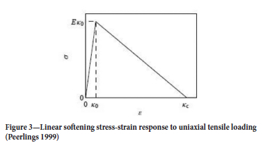
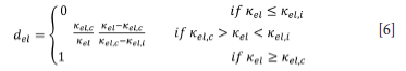
where Kel is a scalar representation of the highest locally attained elastic stain tensor, Kel,i is a scalar representation of the minimum elastic strain at which damage starts to take place, and Kel,c is a scalar representation of the strain tensor which leads to complete damage. Values for Kel,i, and Kel,c are experimentally determined from uniaxial stress tests.
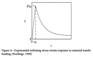
In a real material, however, softening is nonlinear and can be modelled by an exponential softening law (Peerlings 1999):
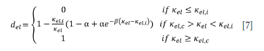
In this instance the material loses stiffness exponentially post damage initialization strain (Figure 4). The parameter b is a temperature-dependent constant which controls the rate of softening. A higher value of b means faster damage growth and thus a more brittle material (Peerlings, 1999). It is important to note that damage when using Equation [7] asymptotically approaches (1 - a)EKel,i (Peerlings. 1999) i.e. a point of zero stress (del = 1) is not reached. Equation [7]. has been used by Damhof, Brekelmans, and Geers (2008) to model thermomechanical damage of refractory material.
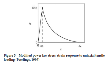
Another elastic damage law proposed by Geers (in Peerlings, 1999) models damage to completion. This model was originally developed for short glass-fibre-reinforced polymers. The so-called modified power law is given by (Figure 5):
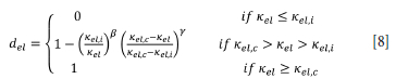
The exact law which governs elastic damage of ilmenite freeze linings is not known. However, the values of Kel,i), Kel,c and a, β have to be determined experimentally in the case of exponential softening, or Kel,i, Kel,c, and y, β in the case that the modified power law should apply. Values of a, β or y, β are the same in tension and compression provided that the loading does not change sign, i.e. no change from compression and tension on the same domain. This is because change from tension to compression or vice versa closes or opens micro-cracks and coalesced micro-cracks respectively. A material which has micro-cracks induced in it behaves differently compared to the virgin material. In the case of reversal from compression to tensile, the material damages more readily in tension compared to the virgin material because of existing micro-cracks or coalesced micro-cracks caused by the compressional load.
Thermal damage
Thermal damage is linked to phase changes and thermophysical changes at low temperatures when the furnace is cooling down and the lining is exposed to air during a stoppage. Such phase changes and thermophysical changes lead to modifications to the mechanical properties of the freeze lining. Phase changes in an ilmenite freeze lining are linked to the anatase/rutile transformation at 400-1000°C, while thermophysical changes are linked to irregular straining of the pseudobrookite due to temperature change.
In similar studies (Damhof, Brekelmans, and Geers, 2009, 2008, 2011a, 2011b) a separation was possible between elastic damage and thermal damage, owing to the slow, gradual progress of thermal damage. In the case of ilmenite freeze linings, however, such a separation is thought to be impossible as the anatase/rutile phase change and irregular straining of the pseudobrookite are held to be fast-acting changes and therefore cannot be separated from elastic damage characterization. As such, only elastic damage will be characterized, with the thermal damage incorporated in the results.
Experimental method: Elastic damage characterization
Sample acquisition
Any attempt to reconstruct the freeze lining would involve crushing slag ingot pieces followed by remoulding to form suitable core sizes. In this study, it was decided to use drill core samples from cooled 25 t bell-shaped slag ingots to represent the freeze lining. The cores were 24 mm in diameter with varying lengths and were taken at Tronox Namakwa Sands in Saldanha, South Africa.
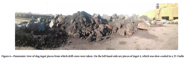
Due to safety concerns around drilling through unsolidified portions of the ingot, the drill cores were not taken directly from the ingots but rather from pieces that had been broken off with a hydraulic hammer. Figure 6 shows a collection of slag ingot pieces from which the drill cores were taken. The sampled ingots followed the Tronox Namakwa Sands cooling process, which involves a primary air-cooling in a 25 t ladle followed by removal of the ingot and secondary cooling with a water spray.
It was anticipated that since the slag ingots are from a production line with tightly controlled chemistry there would not be a significant variability in the ingot compositions. Therefore only four different ingot pieces were sampled. One of the sampled ingot pieces (ingot 4) was slow-cooled in a 25 t ladle for the entire cooling cycle as opposed to being tipped over and spray-cooled after air cooling. This slow cooling process allows the higher-melting components such as pseudobrookite to solidify first on the outer rim of the ingot while the lower-melting components such as silicates solidify last in the centre of the ingot (Pistorius and Kotzé, 2009). However, the slag solidifies to a thickness of 300 to 320 mm during the primary air-cooling stage in the ladle (Kotzé and Pistorius 2010), therefore for the depth of drill cores taken in this study (approximately 40 mm) all cores ought to be same as regards cooling patterns.
A 24 mm inside diameter diamond tip core bit was used to take the samples. Wet drilling was done to avoid wearing of the bit and oxidizing the cores due to the high temperature caused by the drill bit. The same process water used to spray-cool the ingots was used to during wet drilling. Thirty-two drill cores 24 mm 0 by approximately 40 mm were recovered from each ingot.
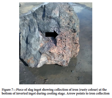
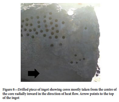
Drilling was done in the direction of heat flow radially in, i.e. from the outside of the ingot where the ingot face interfaced with the ladle towards the centre of the ingot. Care was also taken to drill in the centre of the ingot and not the bottom of the inverted ingot, as iron tended to collect at the bottom of the inverted ingot during spray-cooling (Figure 7). Figure 8 shows a picture of a drilled slag ingot piece in the direction of heat flow and at the centre of the ingot.
Chemical and mineralogical analysis
The chemistry of each ingot was determined from crushed unprocessed drill cores. The cores were pulverized using a planetary mill at 500 r/min for 15 minutes and analysed using X-ray fluorescence (XRF) for chemical analysis and X-ray diffraction (XRD) for mineralogical analysis.
Elastic damage characterization
To determine the elastic damage equation parameters (Kel,i, Kel,c, a, β or β and y ) and elastic properties (E and v) of the freeze lining, uniaxial compression tests were carried out on drill core samples. The tests were conducted in air at temperatures of 25, 125, 350, 550, 750, 950, and 1200°C using an MTS Criterion model 43 machine. Samples were heated in muffle furnace in air for an hour and then quickly placed in the MTS Criterion for compression, a total of 1 minute was taken from the time the sample was removed from the furnace to complete the compression load tests. During this time it is envisaged that no significant temperature change would have taken place in the sample due to the low thermal conductivity of ilmenite slags of 0.5-3.2 W.m-1.°C-1 for a temperature range of 125-1500°C (Kotzé and Pistorius 2010).
A low strain rate of 0.04 s-1 was used. Three repeats at each temperature were done. The Young's modulus of each sample was determined by computing the gradient of the stress vs. strain plot before any damage. An estimate of 0.160 was used for Poison's ratio based on results by Boukendakji (2014) for 70% slag slag-concrete mixtures. The values of (3, y, Kei,c, Kel,i or a and β were determined by model fitting (Equations [6]-[8] to uniaxial compression stress vs. strain curves at different temperatures.
The values of Kel,i and Kel,c are normally determined from tensile load tests (Pearce, Nielsen, and Bicanic, 2004). However, it was thought that the drill cores would not be able to withstand the pressure applied by the clamps of a tensile device. As such, values for Kel,i and Kel,c were first determined in compression and then corrected for tension by dividing by the ratio of compressive strength and tensile strength at the various temperatures. Values for β, y, and a, β are the same in tension and compression (Peerlings et al. 1998; Damhof, Brekelmans, and Geers, 2011a).
Results
Ingot chemistry
The XRF results for the four ingots are shown in Table I. The table shows the eight main constituents together with some species which form part of a silicate phase in solid ingots as opposed to being part of the pseudobrookite phase (SiO2, Al2O3, CaO, and K2O). As expected, there is no significant variation in the chemistry of the ingots, but this cannot be interpreted to mean the ingots can be expected to display the same mechanical behaviour as cooling patterns may differ and thus affect the mechanical properties.
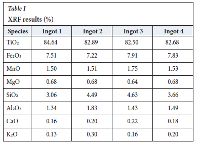
XRD analyses showed that the ingots consist mostly of a single phase. Ingot 1 is 100% Fe0.33Mn0.05Ti2.52O5 (kennedyite); ingot 2 97.2% kennedyite, 0.4 % rutile, and 2.3% quartz; ingot 3 98.7% Mg0.45Ti2.55O5 (magnesium titanium oxide) and 1.3 % rutile;. and ingot 4 98.1% magnesium titanium oxide and 1.9% rutile. Essentially, the ingots were mostly pseudobrookite.
General stress-strain behaviour
Figures 9-12 show the stress-strain responses of the samples from the four ingots.
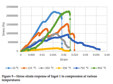
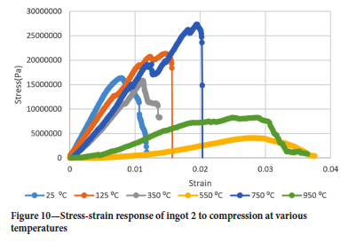
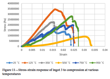
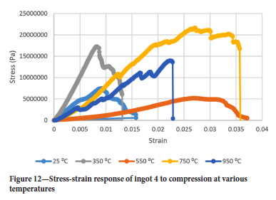
Surprisingly the Young's modulus does not simply decrease with temperature even for temperatures greater than 550°C. Another interesting point is the restoration of the Young's modulus at 750°C to almost the same value as it was at 350°C for ingots 1 and 2 while for ingots 3 and 4 the Young's modulus assumes almost the same value it had at 25°C and 750°C. It was interesting to see that the drill cores behaved in a brittle manner even at 950°C, where one would expect a more ductile response. At 550°C the Young's modulus is lowest for all ingots.
Air pocket closure points can be seen in Figure 9 by the slips in the stress-strain response in the linear region.
Derivation of an appropriate damage law for ilmenite freeze linings
To derive an appropriate damage law for ilmenite freeze linings, Equations [7] and [8] were model-fitted to the results in Figure 9. Microsoft Excel was used to minimize the squared difference between model predictions and raw data by changing the initial damage parameters (Kel,i Kel,x, a, β or β and y). The linear softening law was judged unlikely to be a good predictor of damage given the curved nature of the stress-strain response post damage initialization strain. Figure 13 shows the raw data and stress-strain response as predicted by the exponential softening law for ingot 1 to compression at 25°C.
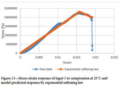
Figure 14 shows the raw data and stress-strain response as predicted by the modified power law for ingot 1 to compression at 25°C.
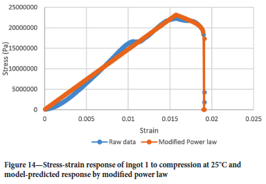
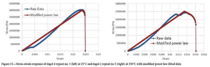
The exponential softening law fails to capture the curvature of the stress-strain response post the damage initialization strain. This is not the case with the modified power law. Thus, the modified power law is deemed appropriate for modelling freeze lining elastic damage during furnace power cycles.
Surprisingly the stress-strain curve post damage initialization strain is convex and not concave as shown in Figures 4 and 5. However, the modified power law can accommodate this change in shape well.
Further examples of how the modified power law fitted the raw data can be seen in Figure 15.
Elastic damage law parameters for ilmenite freeze linings
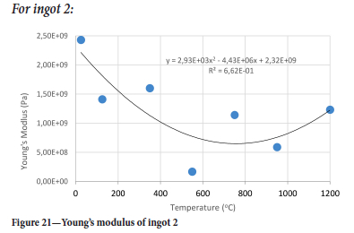
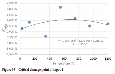
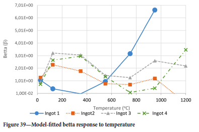
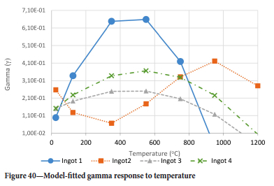
The method of model-fitting the modified power law to the stress-strain response of the four ingots to compression was followed for temperatures 25, 125, 350, 550, 750, 950, and 1200°-C. Tables II-V show the extracted damage parameters at the indicated temperatures. The data is an average of three runs for each temperature. The damage initialization points Kel,i are for compression.
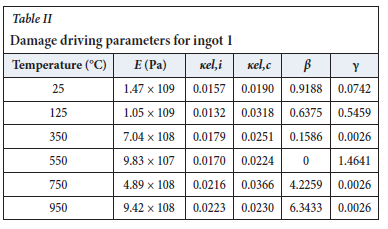
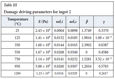
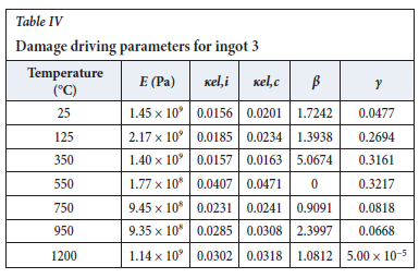
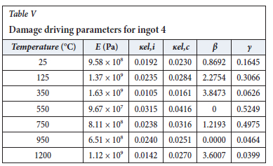
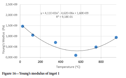
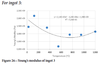
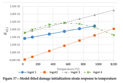
The value of the data in Tables II-V is better appreciated in the form of equations which can be used in finite element method (FEM) codes for a range of inter-experimentally determined temperatures. Figures 16-35 show the extracted damage driving parameters as a function of temperature for the four ingots.
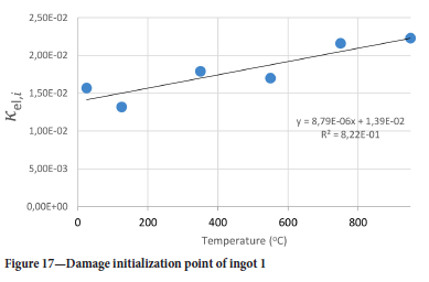
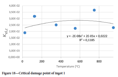
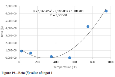
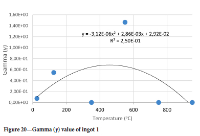
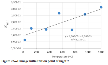
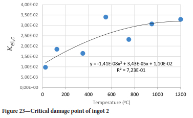
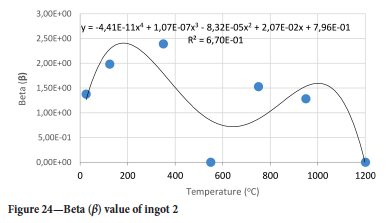
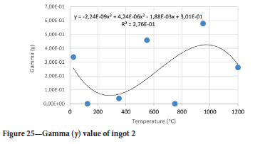
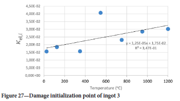
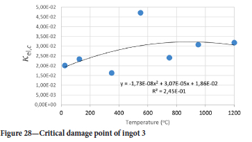
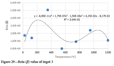
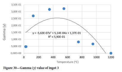
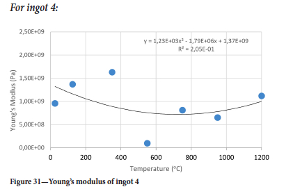
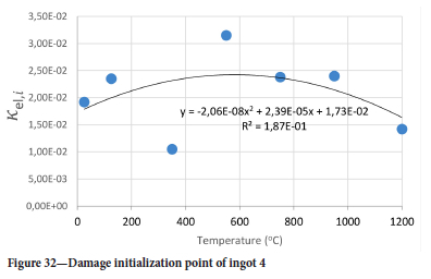
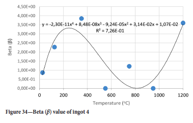
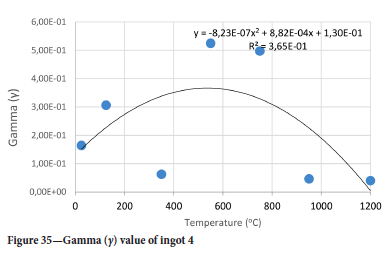
For y care should be taken when using the trend line equations that the value of y does not turn negative. A criterion should be used to keep the value of y to a minimum of 0.0005 to preserve the integrity of Equation [8] even when Kei reaches the critical damage point. The value of β should also be kept to a minimum of zero despite trend line equations.
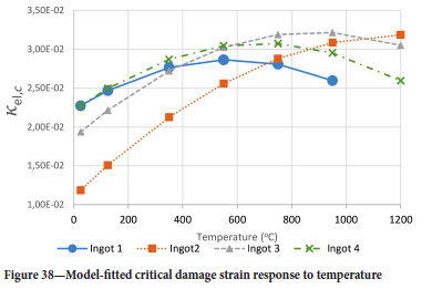
The Young's modulus and critical damage strain are similar in their response to temperature and model fit for all ingots (see Figures 36 and 38). For the other damage parameters, different models predict the response of the damage parameters to temperature for all four ingots. These differences cannot be attributed to chemistry because the chemical makeup of the ingots is similar. The differences are perhaps associated with microstructural detail of the ingots, which is driven by a combination of cooling rates and chemistry of the slag forming the ingots. From this study, one can therefore differentiate between four types of slags forming the freeze lining: slags 1, 2, 3, and 4. These four slags are not the only grouping possible. It is possible that if more ingots were sampled, more slag groupings would be identified due to the 'complex' interaction of slag chemistry and thermal history that affects the mechanical properties of slag ingots and by extension, freeze linings. For the immediate thermomechanical work, however, one can use the four identified slag groupings identified in this study.
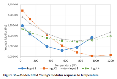
It is of concern that the mechanical response of the slags cannot be linked to the chemistry because this means that the furnace operator cannot control the slag chemistry to influence the mechanical response of the freeze lining within the constraints of meeting production targets (slag quality and quantity).
Conclusion
A furnace freeze lining is used to protect furnace refractories from molten slag attack. Numerous models exist for the growth and depletion of the freeze lining due to thermal imbalances. Knowledge of the freeze lining microstructure under different slag bath conditions also exits. However, no modelling work has been done to date on thermomechanical damage to freeze linings.
A methodology under the framework of continuum damage mechanics is proposed to model mechanical damage to the freeze lining due to phase changes, thermophysical changes, and constrained thermal expansion. Drill cores of solidified slag ingots were used to represent the freeze lining.
The modified power law proved to be a better predictor of the softening behaviour of the drill cores used to represent the freeze lining. Damage driving parameters were extracted from the uniaxial compression raw data at varying temperatures. Governing equations of the damage driving parameters with respect to temperature were derived. No link could be established between the slag chemistry and damage driving parameters. This was due to the tight chemical control practiced by the commercial plant producing the titania-rich slag from which the samples were taken. Despite this, four slag groupings were observed from the model fitting exercise. It is these slag groupings that future investigations will have to model. The damage driving parameters as a function of temperature presented in the study are suitable for use in a finite element method (FEM) code.
Acknowledgements
A special thank you to the staff of University of Botswana's Civil and Mechanical department for the equipment which allowed for this research to take place. Mr John Kennedy for his efforts in organizing the equipment. Mr Bennet Stofberg and the team at Tronox Namakwa Sands for allowing me to take samples of their ingots.
References
Bessinger, D. 2000. MSc thesis, Cooling characteristics of high titania slags. MSc thesis, University of Pretoria. [ Links ]
Bessinger, D., Geldenhüis, J.M.A., and Pistorius, P.C. 2005. Phase changes in the decrepitation of solidified high titania slags. Proceedings of Heavy Minerals 2005. Society for Mining, Metallurgy, and Exploration, Littleton, CO. pp. 213-219. [ Links ]
Boukendakji, M. 2014. Stress-strain behaviour of slag cement concrete. International Journal of Geometallurgy, vol. 7, no. 1. pp. 974-978. [ Links ]
Campbell, A.P., Pericleous, K.A., and Gross, M. 2002. Modelling of freeze layers and refractory wear in direct smelting processes. Iron and Steel Maker, vol. 9, no. 29. pp. 41-45. [ Links ]
Carmeliet, J. 1999. Optimal estimation of gradient Damage Parameters from Localization Phenomena in Quasi-brittle Materials. Mechanics of Cohesive-Frictional Materials, vol. 4. pp. 1-16. [ Links ]
Crivits, T. 2016. Fundamental studies on the chemical aspects of freeze linings. MSc thesis, University of Queensland. [ Links ]
Damhof, F., Brekelmans, W.A.M., and Geers, M.G.D. 2011a. Non-local modelling of cyclic thermal shock damage including parameter estimation. Engineering Fracture Mechanics, vol. 78. pp. 1846-1861. [ Links ]
Damhof, F., Brekelmans, W.A.M., and Geers, M.G.D. 2011b. Predictive FEM simulation of thermal shock damage in the refractory lining of steelmaking installations. Journal of Materials Processing Technology, vol. 211, no. 12. pp. 2091-2105. [ Links ]
Damhof, F., Brekelmans, W.A.M., and Geers, M.G.D. 2009. Experimental analysis of the evolution of thermal shock damage using transit time measurement of ultrasonic waves. Journal of the European Ceramic Society, vol. 29. pp. 1309-1322. [ Links ]
Damhof, F., Brekelmans, W.A.M., and Geers, M.G.D. 2008. Non-local modelling of thermal shock damage in refractory materials. Engineering Fracture Mechanics, vol. 75. 470064720. [ Links ]
De Villiers, J.P.R., Göske, J., and Tuling, A. 2005. Disintegration in high grade titania slags: low temperature oxidation reactions and associated fracture mechanics of pseudobrookite. Mineral Processing and Extractive Metallurgy, vol. 114. pp. 73-79. [ Links ]
Fallah-Mehrjardi, A., Hayes, P.C., and Jak, E. 2014. Further experimental investigation of freeze-lining-bath interface at steady-state conditions. Metallurgical and Materials Transactions B, vol. 45B. pp. 2040-2049. [ Links ]
Garbers-Graig, A.M. and Pistorius, P.C. 2006. Slag-refractory interactions during the smelting of ilmenite. South African Journal of Science, vol. 102. pp. 575-580. [ Links ]
Heindl, R.A. 1933. The thermal expansion of refractories to 1800°C. Bureau of Standards Journal of Research, vol. 10, no. 6. pp. 715-733. [ Links ]
Kalliala, O., Kaskiala, M., Suorttu, T., and Taskinen, P. 2015. Freeze lining formation on water cooled refractory wall. Transactions of the Institution of Mining and Metallurgy: Section C, vol. 124, no. 4. pp. 224-232. [ Links ]
Kotzé, H. and Pistorius, P.C. 2010. A heat transfer model for high titania slag blocks. Journal of the Southern African Institute of Mining and Metallurgy, vol. 110. pp. 57-66. [ Links ]
Pearce, C.J., Nielsen, C.V., and Bicanic, N. 2004. Gradient enhances thermo-mechanical damage model for concrete at high temperatures including transient thermal creep. International Journal for Numerical and Analytical Methods in Geo-mechanics, vol. 28. pp. 715-735. [ Links ]
Peerlings, R.H.J. 1999. Enhanced damage modelling for fracture and fatigue. PhD thesis, Technical University of Eindhoven. [ Links ]
Peerlings, R.H.J., de Borst, R., Geers, M.G.D., and Geers, M.G.D. 1998. Gradient enhanced damage modelling of concrete fracture. Mechanics of Cohesive-Frictional Materials, vol. 3. pp. 323-342. [ Links ]
Pistorius, P.C. 2008. Ilmenite smelting: The basics. Journal of the Southern African Institute of Mining and Metallurgy, vol. 108. pp. 35-43. [ Links ]
Pistorius, P.C. and Kotzé, H. 2009. Role of silicates phases during comminution of titania slag. Mineral Engineering, vol. 22. pp. 182-189. [ Links ]
Polanco-Loria, M. and S0rensen, S.I. 1995. Damage evolution laws for concrete - A comparative study. Fracture Mechanics of Concrete Structures. Wittmann, H. (ed.). Aedificatio, Freiburg. pp. 1027-1036. [ Links ]
Stana, R.H. 2016. Solidification of titanium slags and influence on post processing. Master's thesis, Norwegian University of Science and Technology. [ Links ]
Verscheure, K., van Camp, M., Blanpain, B., Wollants, P., Hayes, P.C., and Jak, E. 2005. Investigation of zinc fuming processes for the treatment of zinc-containing residues. Proceedings of the John Floyd International Symposium on Sustainable Developments in Metals Processing, Melbourne, Australia, 3-6 July 2005. Nilmani, M. and Rankin, J. (eds). Australasian Institute of Mining and Metallurgy, Melbourne. [ Links ]
Zietsman, J.H. 2004. Interaction between freeze lining and slag bath in ilmenite smelting. PhD thesis, University of Pretoria. [ Links ]
 Correspondence:
A. Mabentsela
Email:arthurmabentsela@gmail.com
Received: 9 Jun. 2020
Revised: 10 Oct. 2022
Accepted: 11 Nov. 2022
Published: January 2023

