


Services on Demand
Article
 English (pdf)
 Article in xml format
 Article references
Indicators

Related links
-
 Cited by Google
 -
 Similars in Google
Share

 Permalink
Journal of the Southern African Institute of Mining and Metallurgy
On-line version ISSN 2411-9717
Print version ISSN 2225-6253
J. S. Afr. Inst. Min. Metall. vol.122 n.10 Johannesburg Oct. 2022
http://dx.doi.org/10.17159/2411-9717/1983/2022
PROFESSIONAL TECHNICAL AND SCIENTIFIC PAPERS
An improved pillar design methodology
K.V. JessuI; A.J.S. SpearingII; M. SharifzadehIII
IWA School of Mines, Curtin University
IIChina University of Mining & Technology. https://orcid.org/0000-0002-1839-9887
IIIKey Laboratory of Deep Metal Mines, Northeastern University
SYNOPSIS
Empirical pillar design methods are commonly used in the mining industry. The parameters within which these methods are valid are frequently unknown to the user or ignored. In addition, empirical design may not consider essential parameters such as blasting effects, orebody dip and the presence of geological structures, which all adversely affect the stability of the pillars. This can result in potentially serious pillar design strength over-estimates. Although the commonly based tributary area method is generally conservative, as the spans are seldom that large relative to the depth, failing to consider other relevant parameters can result in errors. Problems associated with an under-designed pillar can range from a local pillar collapse to a catastrophic chain reaction collapse (or run). Over-designed pillars are generally safe but reduce the extraction of the orebody, thus adversely affecting the profitability of the mining operation. We used laboratory tests and numerical modelling to understand the effects of pillar orientation, blasting and the presence of discontinuities on pillar strength. Reduction factors were developed with these models to be implemented in conjunction with the existing empirical pillar design methods. For any pillar or mine design, once it is implemented, the actual performance of the system must be checked regularly by observation and monitoring and adjusted if needed. The pillar design approach outlined in this paper can better optimize the pillar mining method by considering other generally ignored but important parameters, thus improving safety, productivity, and economic aspects.
Keywords: pillar, tributary area theory, geological structures, orebody dip, width-to-height (W/H) ratio.
Introduction
The safe and effective design of pillar systems is vital in many mining methods, especially for room-and-pillar mining. From an economic point of view, maximizing the room width and minimizing the pillar size is important, but overall stability and safety are the overriding design considerations. The performance of the hard-rock pillars is mainly affected by the width-to-height ratio and the rock mass properties of the pillars, and the immediate roof and floor strata. Other conditions, however can also influence it to some extent, such as pillar inclination, the orientation of any discontinuities and the effects of adjacent blasting on the pillars. Current empirical design approaches tend not to consider these parameters, although their impact, can be significant. The effects of these factors were investigated and quantified using multiple laboratory-scale tests and numerical analyses on hard-rock pillars.
Pillar types
In any underground mining operation, there are broadly two different categories of pillars: local support pillars and protective pillars. The differences between the two categories of pillars are often not clearly apparent, and there are instances when pillars fulfil both requirements. There are a number of significant differences between the two types of pillars.
Support pillars
Support pillars can be further divided into two classes: pillars that provide local support and pillars that provide regional support. However, pillars often provide both local and regional support. A good example of this is a conventional room-and-pillar mining layout that has been designed with a high safety factor. Local support pillars are often only temporary and are extracted once they have fulfilled their purpose. One of the interesting aspects of local support pillars is that their useful function is often limited to the time when actual mining takes place in their immediate vicinity. Subsequent failure of these pillars can occur, provided the mode of failure is stable. Yielding support pillars fall into this category. Barrier and wide inter-panel pillars are typical examples of pillars that provide regional support.
Protective Pillars
During mining, it often becomes essential to protect underground and surface structures from the effects of mining. One of the practical means of achieving this is to leave portions of the orebody unmined to form protective pillars. The design criteria for these pillars depend largely on the nature of the structure that needs to be protected. In the case of surface structures, the design criterion is based on the magnitude of the surface movements and strains that can be tolerated by the structure. In the case of underground structures such as bunkers, pump stations, service excavations, etc., it is usually the magnitude of the stresses that determines the size of protective pillars. A common example of this is shaft protection.
A brief review of common empirical approaches for pillar design
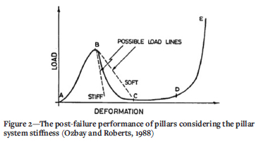
The dimensions of a pillar obviously have a significant effect on the strength and the post-failure performance of a pillar, as shown in Figure 1. In addition, the depth (the stress tensor) at which pillars are used is also important as the design approach is different. Rigid or yielding pillars may be required, and the post-failure behaviour of pillars governs whether they fail in a controlled (desirable) or uncontrolled manner (usually sudden and violent). This is illustrated in Figure 2. Strain-softening post pillar failure usually indicates violent pillar failure potential.

Pillar loading distribution conditions are complex as the pillars are 'built' from a non-uniform rock mass and the difficulties in determining the in-situ strength properties of the pillar material dictate that a simplified approach is adopted in the design. Instead of determining the maximum stress that acts in the pillar, the average pillar stress is commonly used as it is easier to estimate. In addition, rather than using the actual strength of the pillar material, empirical formulae that predict the strength of the whole pillar have been developed and modified over time. These formulae suffer from the constraint that they are site-specific and valid only for the conditions for which they have been derived. Users of such empirical formulae often fail to consider this when using them.
The theoretical pillar stress is usually obtained by using the simplistic tributary area theory (as outlined in Figure 3); otherwise, some form of computer analysis program is used. The tributary area theory ignores the effects of abutments and hence is only applicable where the span of the mining in both directions is at least equal to the depth of mining below the surface. Should this not be the situation, the pillar loads obtained will be substantially higher than the actual pillar loads resulting in a conservative approach, which is at least a safe approximation.
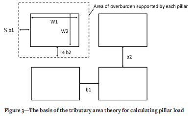
The total tributary area supported by a pillar is:

The area of the pillar is:

Assuming the depth of the pillars to be h (in km) and the average rock density to be p, the overburden stress is:

The pillar load (stress) is, therefore

The percentage extraction (e) is equal to:

The limitations or constraints of tributary area theory are that it:
> It is only valid for a flat-dipping pillar (i.e., no pillar shear)
> Assumes that the pillars are all evenly loaded, which in reality is seldom the case
> Ignores the presence of abutments (which makes it conservative, therefor safer)
> Does not account for any mining-induced deformation or failure
> Ignores the overburden properties (e.g., the stiffness and geology).
As can be seen from Figure 1, the strength of a pillar is strongly influenced by the width-to-height ratio, and this is a key parameter in all empirical pillar design formulae.
One of the first comprehensive pillar studies was undertaken by Obert, Windes, and Duvall (1946), who conducted tests using various rock types with width-to-height ratios from 0.5 to 3.0. They established the following empirical relationship:

where σ0 is the compressive strength of the rock specimen with a width/height ratio of unity.
Pillar design received much more intense focus and research after the Coalbrook Mine disaster in South Africa. On January 21, 1960, a massive pillar collapse occurred, and 437 miners were killed. Salamon and Munro (1967) developed the following formula after investigating stable and unstable coal mine pillars in South Africa:

where K is a constant depending on the strength of the coal, W is the square pillar width, and H is the effective pillar height. Based on their work, K for South African coal mines was found to be 7.2 MPa.
Bieniawski (1968) developed a pillar strength formula as follows:

where σcc is the strength of a critical sized cubic sample, Wp is the smallest pillar dimension, and H is the effective pillar height.
A similar approach to hard-rock pillar investigations was undertaken by Hedley and Grant (1972), who investigated both stable and unstable quartzite pillars in Canadian uranium mines and expressed the strength of the pillars using a similar formula to that used by Salamon and Munro:

where K is the unit strength of the rock, W is the square pillar width and H is the effective height of the pillar. Based on their work, K for the quartzite was found to be 133 MPa.
Lunder (1994) increased the database to 178 case histories from Canadian mines and included the confinement effect component for pillars with W/H ratio > 1. This is currently the most common empirical approach used in designing the hard rock pillars in mines, as follows:

where K is the pillar size factor, UCS is the uniaxial compressive strength (MPa), C1 and C2 are the empirical rock mass constants and k is the friction term which is calculated as:

Esterhuizen, Dolinar, and Ellenberger., (2008) included discontinuities in the pillar for pillar strength estimation based on numerical modelling as:

where LDF is the large discontinuity factor.
It should, however, be noted that no pillar failures have been reported at a width-to-height ratios of greater than 3.6. The application of these formulae outside of the parameters included in the database is not recommended under any circumstances.
It can be seen that none of the above empirical designs (with the exception of Esterhuizen (2008), which is limited to limestone) specifically investigate the effects of dip, blast damage, and the presence of discontinuities. While the data-sets used by the various researchers could have included some of these conditions, their effects would have been largely negated by using averages.
The use of rectangular pillars
In a detailed study of the failure process of coal pillars, Wagner (1980), showed that the failure commences at the circumference of the pillar and migrates inwards. On the basis of these observations, it was suggested that the ratio of the area, Ap, to the circumference, C, of a coal pillar has a strong influence on the pillar strength. Accordingly, the effective width, in metres, of a pillar of irregular shape is defined as:

where Ap is the area of the rectangular pillar and C is the circumference.
Rectangular pillars are often used along with main entries in order to limit the number of costly and time-consuming ventilation stoppings, in inclined orebodies to help resist the induced shear caused by mining or help clamp potentially unstable major geological features.
Pillar factors of safety
The greatest hazard associated with pillar mining is the potential for massive pillar failure and collapse. Sudden failure is not always preceded by pillar spalling, and once failure starts, it is virtually impossible to control or stop.
Most factor of safety (FOS) calculations for pillars are based on the duration and importance of the specific pillars. For example, in conventional room-and-pillar panel designs, a FOS of 1.6 is generally accepted, while for barrier pillars a FOS of 2.0 is more commonly used.
A relevant empirical design method exercise on a mine must include the following information and investigations:
> The unconfined compression strength (UCS), Young's modulus, and Poisson's ratio of the orebody itself at numerous locations to determine the distribution of those parameters and an average value and standard deviation
> The stratigraphic column at various locations above the orebody to determine the overburden lithology, geological structures, and average rock density
> Actual pillar dimensions
> Orebody delineation and inclination of the mining method
> Depth of damage due to blasting
> Major discontinuities and their orientations with respect to the pillars.
The collection and processing of the above data could give great insight for designing and proving pillar designs by identifying potential instabilities that the use of average stresses and strengths would not typically reveal. This technique can therefore be used to determine the actual FOS required.
Improving the applicability of empirical design equations
Empirically-based pillar design formulae specifically consider failed and unfailed pillars without considering the reasons for failure. In general the following specific effects are not considered:
> Blasting on hard-rock pillars
> The inclination of the seam or orebody
> Orientation of discontinuity with respect to the pillar
> Regular monitoring of the pillars and updating the empirical pillar design equations for a specific site.
Laboratory tests and numerical modelling were conducted to develop an understanding of the parameters such as inclination, rectangular shape, inclination, and blasting effects on the strength of the pillars. Laboratory samples were prepared as per the ISRM standards for uniaxial compressive strength, which were then used as a reference for different widths to height of the samples to determine the pillar strength. Numerical modelling was developed in FLAC3D and calibrated with the Lunder and Pakalnis (1997) empirical equation, and all the parameters were then tested to determine their influence on the strength of the pillars.
Laboratory tests were conducted on gypsum, sandstone, and white sandstone samples with diameters of 42 mm and 52 mm (Figure 4). The samples were prepared as specified in ISRM standards with four different W/H ratios. Three specimens were created of each rock type for four different W/H ratios, resulting in 48 specimens in total for testing. Uniaxial compression loading was applied onto the specimens with the servo-controlled computer Program GCTS CATS 1.8. Displacement loading rate of 0.12 mm/min was applied so as to cause failure within 5-10 minutes as per the ISRM standards.

Numerical modelling was conducted using FLAC3D, a three-dimensional finite-difference modelling package to simulate the pillars and develop stress-strain curves for pillar strength analysis. The model consists of roof, pillar, and floor with a constant height and varying width and length of the pillar to achieve different width-to-height ratios for square and rectangular pillars with a 75% extraction ratio. The height of the roof and floor were kept at three times the pillar height to avoid the boundary effects. Roller supports were positioned on the sides of the model while fixed supports were positioned at the bottom of the floor. Uniform velocity was applied on the top of the roof to simulate the loading of the pillars (Lorig and Cabrera, 2013).
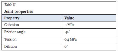
The bilinear strain-hardening/softening ubiquitous joint model is based on the bilinear strength envelope by Kaiser et al. (2000) to simulate the failure mechanism of the pillars realistically. The rock and joint properties were obtained from Esterhuizen (2006) as shown in Tables I and II.

Effect of orebody inclination on pillar strength
An increased pillar inclination increases the potential for sliding on weak planes. A series of laboratory tests and numerical modelling were conducted to determine the effect of dip on the strength of pillars (Jessu and Spearing, 2018). Figure 6 shows that pillar strength reduces with the inclination of the pillars and is consistent throughout the width-to-height ratios. For detailed information, see Appendix A. A reduction factor was evaluated to determine the pillar strength at different inclinations as per Equation [15].

Maximum load reduction results:

Limitations of this theory include the inadequate amount of laboratory tests that have been conducted on the samples, which range only between inclinations of 0° and 20°. Another constraint that must be taken into consideration is the range of width-to-height ratios for which experiments are conducted, i.e. W/H ratios of 0.5 and 2.0. The failure mechanisms in the laboratory tests and the numerical modelling show similar results, which indicates the potential for the reduction factor of the FOS for inclined pillars.
Effect of orebody inclination on rectangular pillars In tabular orebodies, rectangular pillars are commonly used. Numerical modelling was undertaken to understand the effects of orebody inclination on the strength of the rectangular pillars (Jessu and Spearing, 2019). Figure 7 shows an example of the effects of orientation of the rectangular pillars with respect to the dip of the orebody. These investigations showed that the rectangular pillars at low width-to-height ratios (less than 1.0) had similar strength in strike and dip directions at all inclinations. Rectangular pillars along the dip showed a marginal increase in strength compared to the rectangular pillars along the strike when the width-to-height ratio was greater than 1.0.

Limitations to the numerical modelling conducted on rectangular pillars include the mining spans, which have always been constant of 75% extraction ratio. The equivalent W/H ratios for the rectangular pillars shown in Figure 7 were calculated using Equation [9]. Width-to-height ratios were only considered in the range of 0.5 to 1.5, and the length was also constrained to only three times that of the width.
Effects of discontinuity dip on pillar strength
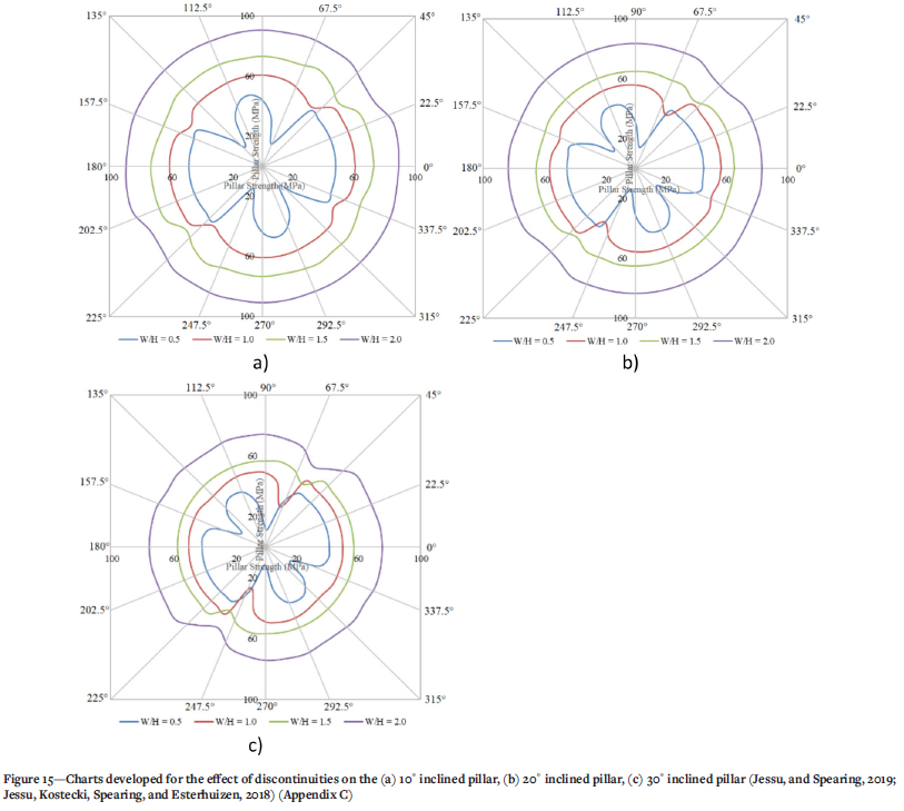
The dip of the discontinuity has a dominant effect on the pillar bearing capacity, specifically when the dip is between 30° and 60°. Jessu, Spearing, and Sharifzadeh (2018) researched the influence of discontinuities in horizontal and inclined pillars. The results show that a discontinuity has a minimal effect on pillars with a larger width-to-height ratio in horizontal pillars. However, in inclined pillars, the effects of a discontinuity are much greater for large W/H ratios than for horizontal pillars. The presence of discontinuities that are in a similar direction to the shear failure mechanism of an inclined pillar reduces the strength of such pillars, as shown in Figure 8.
Charts were developed to determine the reduction factors to be utilized for the presence of discontinuities in horizontal and inclined pillars (Appendix C). For example, the strength of a horizontal pillar with W/H ratio of 0.5 is 50 MPa, and the discontinuity dip angle of 45° reduces the pillar strength to 32 MPa due to the shearing along the discontinuity (Figure 8). In inclined pillars, as the brittle failure is dominant also with large W/H ratios, the shearing along the discontinuity is more pronounced.
The effects of discontinuity depend mainly on the properties of the discontinuity. The charts represent only one set of properties for the discontinuity but can be used as a guide towards determining the range of orientations that can affect the horizontal and inclined pillars.
Effects of blasting on pillar strength
Shock waves and gas-induced fractures from blasting cause deterioration in the rock mass and may create new fractures which consequently decrease the pillar rock strength. Jessu, Spearing, and Sharifzadeh (2018) conducted numerical modelling on the strength of the pillars, accounting for blast damage with the help of a parametric study with factors such as W/H ratio, disturbance factor, and damage thickness. It was determined that slender pillars (W/H < 0.8) do not show any difference in strength even with blast damage on the sides, due to the violent failure of the pillars from the core. Failure of the larger pillars initiates from the sides, and as the sides of the pillar are damaged due to the blasting, it was determined that the strength diminishes due to the reduction of the pillar core.
The two important factors for blast damage were the damage factor and damage thickness around the pillar. These factors yielded a maximum reduction of about 7% for a W/H ratio of 0.5, 16% for W/H ratio of 1.0, 22% for W/H ratio of 1.5, and 27% for W/H ratio of 2.0. A strength reduction factor was evaluated for a blast damage factor of 1.0 and maximum blast damage of 1 m around the pillar sides, as shown in Figure 9. A linear relationship developed between the average strength factors due to blasting (RFB) and width-to-height ratio of the pillars can be written as:


This reduction factor is based on the maximum blast damage that can occur on the pillar, which can be quite conservative. A table (Appendix B) has been developed by Jessu, Spearing and Sharifzadeh (2018) to evaluate the reduction factors for different blast damage factors and blast damage thickness. One of the main limitations is the specific range of the width-to-height ratio (between 0.5 and 2.5).
In-situ monitoring to improve the empirical equations
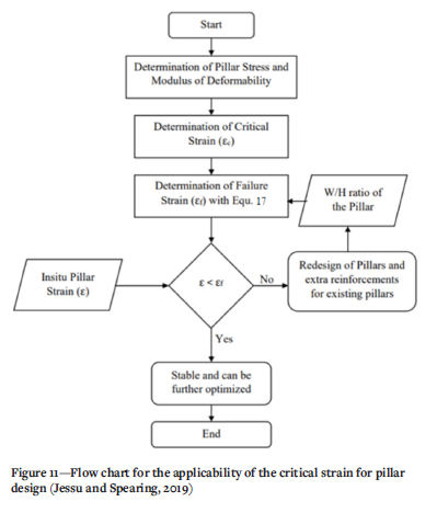
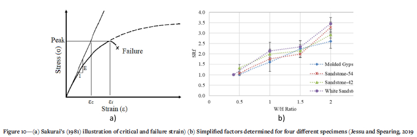
Jessu and Spearing (2019) adopted Sakurai's direct strain evaluation method (Sakurai, 1981) to establish an equivalent equation for the stability of pillars (Figure 10a). This method comprises in-depth analysis of stress-strain curves where the critical strain is defined as the ratio of the peak uniaxial compressive strength (UCS) to the elastic modulus. The strain at the peak UCS is defined as the failure strain. The reduction factor was derived from the ratio of critical strain to failure strain. Laboratory tests were conducted with different width-to-height ratios (Figure 10b) to observe the failure strain and to evaluate the critical strain, from which an equation was developed (Equation [17]).

where SRf is a simplified factor, which is the ratio of failure strain (ef) to critical strain (eC). A flowchart was developed to continuously monitor the in-situ pillars and make the necessary changes to the empirical equations, as shown in Figure 11.
Proposal for the improved pillar design methodology
Based on the authors' experience and knowledge, a new insight into the pillar design process is proposed. For this purpose, a step-by-step procedure, as illustrated in Figure 12, is required to develop a safe and optimized pillar design. As indicated in the pillar design methodology, a large number of factors are involved and contribute to the strength characteristics of a pillar. The first step consists of choosing the most appropriate pillar formula for the specific situation, such as the Salmon and Munro, (1967) equation for coal mines and Lunder and Pakalnis, 1997 equation for hard-rock mines. The second step comprises determining the pillar and room dimensions appropriate for the depth, rock strength, and required extraction ratio with an initial acceptable FOS. Then the various factors, such as the orientation of the orebody, excavation method and presence of geological features are incorporated to design an appropriately sized pillar with final desirable FOS.

Continuous geotechnical monitoring of the pillars needs to be conducted via inspections to improve the performance of the pillars in situ and the pillar design methodology. For example, the monitoring could involve measuring room and intersection width, the actual pillar dimensions, the pillar fracturing using a borescope, and pillar stress changes using flat-jacks. This would guide back-analysis of the empirical equations and can be reformed to improve the performance of the pillars.
Conclusions
Mine local and global stability depend strongly on pillar stability. The failure of one pillar will increase the load (possibly suddenly) on neighbouring pillars, which can cause the failure of other pillars in a domino effect. In this research, therefore, the main factors affecting pillar stability such as pillar inclination and width-to-height ratio were investigated and a comprehensive methodology for pillar design proposed. The following conclusions have been drawn based on the proposed improvised pillar design methodology.
> With the step-by-step approach, all the factors such as orientation of the orebody, excavation methods, and presence of geological features can be accounted for when designing the pillars.
> When the pillars are monitored in situ, the date can be back-analysed to improve the design process and pillar performance.
> Each factor has a reduction factor, as these factors adversely affect the strength of the pillar compared to horizontal pillars with non-explosive mining method and with minimal presence of geological features.
> Limitations to this work on the reduction factors/ corrections include the range of width-to-height ratios investigated (between 0.5 and 2.0), and range of orebody orientations considered from (0° to 40°).
Implementation of the proposed pillar design methodology could optimize mine safety, productivity, and economics.
Author contributions
Conceptualization, K.J. and A.S.; methodology, K.J.; software, K.J.; validation, K.J., A.S., and M.S.; formal analysis, K.J.; investigation, K.J.; resources, A.S. and K.J.; data curation, K.J.; writing-original draft preparation, K.J. and A.S..; writing-review and editing, A.S., K.J. and M.S.; visualization, K.J. and A.S.; supervision, A.S.; project administration, A.S. and K.J., funding acquisition, A.S. All authors have read and agreed to the published version of the manuscript.
Funding
This research received no external funding but Curtin University kindly provided Kashi Jessu with a PhD scholarship.
Data availability
Mainly found in the paper Appendices.
References
Bieniawski, Z.T. 1968. The effect of specimen size on the strength of coal. International Journal of Rock Mechanics and Mining Sciences, vol 5. pp.325-335. [ Links ]
Das, M. 1986. Influence of width to height ratio on post failure behaviour of coal. International Journal of Mining and Geological Engineering, vol. 4. pp. 67-77. [ Links ]
Esterhuizen, G.S. 2006. An evaluation of the strength of slender pillars. Transactions of Society for Mining, Metallurgy, and Exploration, vol. 320. pp. 69-76. [ Links ]
Esterhuizen, G.S., Dolinar, D.R. and Ellenberqer, J.L. 2008. Pillar strength and design methodology for stone mines. Proceedings of the 27th International Conference on Ground Control in Mining. Morgantown, WV.West Virginia University. pp. 241-253. [ Links ]
Hedley, D.G.F. and Grant, F. 1972. Stope and pillar design for the Elliot Lake uranium mines. CIM Bulletin. vol. 65. pp. 37-44. [ Links ]
Jessu, K.V., Kostecki, T.R., Spearinq, A.J.S., and Esterhuizen G.S. 2018. Effect of discontinuity dip direction on hard rock pillar strength. SME Transactions, vol. 344. pp. 25-30. [ Links ]
Jessu, K.V. and Spearinq, A.J.S. 2018. Effect of dip on pillar strength. Journal of the Southern African Institute of Mining and Metallurgy. vol. 118. pp.765-776. [ Links ]
Jessu, K.V. and Spearinq, A.J.S. 2019. Direct strain evaluation method for laboratory based pillar performance. Journal of Rock Mechanics and Geotechnical Engineering. vol 11, no. 4. pp. 860-866. [ Links ]
Jessu, K.V. and Spearinq, A.J.S. 2019. Performance of inclined pillar with a major discontinuity. International Journal of Mining Science and Technology. vol. 29, no. 3. pp. 437-443. [ Links ]
Jessu, K.V., Spearinq, A.J.S., and Sharifzadeh M. 2018. A parametric study of blast damage on hard rock pillars. Energies, vol. 11, no. 7. p. 1901. [ Links ]
Kaiser, P.K, Diederichs, M.S., Martin, C.D., Sharp, J., and Steiner, W. 2000. Underground works in hard rock tunnelling and mining. Proceedings of GeoEng2000, Melbourne Tectonic, Lancaster, PA. pp. 841-926. [ Links ]
Loriq, L.J. and Cabrera, A. 2013. Pillar strength estimates for foliated and inclined pillars in schistose material. Proceedings of the 3rd Internationsal FLAC/DEM Symposium, Hangzhou, China. Paper 01-01. Zhu, H., Detournay, C., Hart, R, and Nelson, M. (eds). Paper 01-01. Itasca International Inc. 2013, Minneapolis. [ Links ]
Lunder, P.J. 1994. Hard rock pillar strength estimation: An applied approach. Maset thesis. University of British Columbia. [ Links ]
Lunder, P.J. and Pakalnis, R. 1997. Determination of the strength of hard rock mine pillars. CIM Bulletin. vol. 90. pp. 51-55. [ Links ]
Ozbay, M.U. and Roberts, M.K.C. 1988. Yield pillars in stope support. Proceedings of the SANGROM Symposium, Swaziland. South African National Group on Rock Mechanics, Johannesburg. pp. 317-326. [ Links ]
Obert, L., Windes, S.L., and Duvall, W.I. 1946. Standardized tests for determining the physical properties of mines rocks. 3891 US Bureau of Mines Report of Investigations. [ Links ]
Sakurai, S. 1981. Direct strain evaluation technique in construction of underground opening. Proceedings of the 22nd US Symposium on Rock Mechanics, American Rock Mechanics Association, Alexandria. pp. 278-82. [ Links ]
Salamon, M.D.G. and Munro, A.H. 1967. A study of the strength of coal pillars. Journal of the South African Insitute of Mining and Metallurgy. vol. 68. pp. 55-67. [ Links ]
Wagner, H. 1980. Pillar design in coal mines. Journal of the South African Institute of Mining and Metallurgy, vol. 80, no. 1. pp. 37-45. [ Links ]
 Correspondence:
A.J.S. Spearing
Email: ajsspearing@yahoo.com
Received: 12 Jan. 2022
Revised: 17 Jul. 2022
Accepted: 15 Jul. 2022
Published: October 2022
Appendix A
Flow chart for the application of dip correction (Figure 13).

Appendix B
Jessu, Spearing, and Sharifzadeh (2018) developed tables with the help of a parametric study, as shown in Table III.

A flow chart was developed to apply the blast correction for the improved pillar design methodology as shown in Figure 14 (Jessu, Spearing, and Sharifzadeh, 2018).

Appendix C
Charts were developed for all the different discontinuity orientations with respect to pillar inclination to determine the reduction factors (Figure 15).
The flow chart in Figure 16 was developed to apply the adverse discontinuity correction (Jessu and Spearing, 2019; Jessu, Kostecki, Spearing and Esterhuizen,(2018).


