


Servicios Personalizados
Articulo
 Inglés (pdf)
 Articulo en XML
 Referencias del artículo
Indicadores

Links relacionados
-
 Citado por Google
 -
 Similares en Google
Compartir

 Permalink
Journal of the Southern African Institute of Mining and Metallurgy
versión On-line ISSN 2411-9717
versión impresa ISSN 2225-6253
J. S. Afr. Inst. Min. Metall. vol.122 no.7 Johannesburg jul. 2022
http://dx.doi.org/10.17159/2411-9717/1574/2022
PROFESSIONAL TECHNICAL AND SCIENTIFIC PAPERS
Modelling and analysis of a hydraulic support prop under impact load
G.D. ZhaiI, II; X. YangI, II
IState Key Laboratory of Coal Resources and Safe Mining, China University of Mining and Technology (Beijing), Beijing, China. X. Yang: https://orcid.org/0000-0001-7948-8552; G.D. Zhai: https://orcid.org/0000-0002-5379-3337
IISchool of Mechanical, Electronic and Information Engineering, China University of Mining and Technology (Beijing), Beijing, China
SYNOPSIS
The prop is the most important part to ensure the proper functioning of hydraulic support. When the hydraulic support is impacted by the roof, the prop is prone to extrusion deformation, expansion, and even bursting. In order to study the stress on a doubly-telescopic hydraulic support prop under impact load, an impact simulation was carried out based on the drop weight method. First, the impact model of the hydraulic system of the prop was established in AMESim software and the dynamic response curves of the bottom and middle cylinder of the prop obtained. Then, according to the conservation of energy, the pressure formulaes in the hydraulic cylinder of the prop under impact load were derived and verified by the AMESim simulation results, and the maximum pressure on the inner surface of the hydraulic cylinder of the prop obtained. Lastly, the transient dynamic simulation of a hydraulic support prop was carried out in ANSYS Workbench software, and cloud diagrams of stress and deformation of the prop obtained using Workbench simulation. The AMESim simulation process describes the change in fluid pressure in the prop, and the pressure formulae can be used to estimate the internal pressure of the prop under impact load. The finite element analysis results show that the stress of the middle hydraulic cylinder is much greater than that on the bottom hydraulic cylinder under impact load, which can provide a reference for prop design.
Keywords: hydraulic support, impact load, transient dynamic simulation, AMESim.
Introduction
Hydraulic support is the main support method in underground coal mining. In coal mining, the working environment of hydraulic support is very complex. The load on hydraulic support mainly arises from two sources: the static load imposed by the roof and the dynamic load caused by rock block rotation or sliding (Witek and Prusek, 2016; Jasiulek et al., 2019; Cao et al., 2018; Ardehjani, Ataei, and Rafiee, 2020). The dynamic impact load acting on the support is much greater than the static load. Generally, under dynamic load, the cylinder of the prop will expand, bend, or deform, and in serious cases this will cause the collapse of a large area of the coal mine roof (Verma and Deb, 2013; Boutrid et al., 2016; Wang et al., 2018; Trueman, Lyman, and Cocker, 2009). As the main part of the whole hydraulic support system , the prop plays an essential role in supporting, and its function directly affects the working performance of the hydraulic support (Singh and Singh, 2010; Pytlik, 2015; Meng et al., 2020). Therefore, it is of great importance to analyse the mechanical properties of the prop under impact load.
International scholars have presented some significant research results related to hydraulic support props. Klishin and Tarasik (2001) established a mathematical model of hydraulic support under dynamic load, deduced the rigidity coefficient of the support, and carried out the dynamic load tests on hydraulic support. Zeng et al. (2018) used ADAMS software to establish a numerical simulation model for a double telescopic prop, and deduced the equivalent stiffness of hydraulic support through theoretical calculation. Through theoretical calculation and analysis, Klishin and Tarasik (2001) and Zeng et al. (2018) respectively derived the dynamic load coefficient and the equivalent stiffness of hydraulic support. Singh (2009) proposed a numerical modelling method to evaluate the performance of hydraulic support. By using the concept of ground reaction curves (GRC), Prusek, Plonka, and Walentek (2016) observed the pressure changes in the hydraulic cylinder and obtained a relationship between the height of the hydraulic support and the pressure changes in the prop with time. According to Chinese standard MT313-1992 and European standard EN 1804-2-2001, Wang et al. (2013) applied 1.5 times and twice the rated axial load to the prop using the finite element analysis method, and carried out stress analysis and stability analysis of the prop. Based on fluid mechanics and fluid-solid coupling theory, Yang et al. (2020) simulated the force state of the hinge joint when the upper surface load acts on the top beam of the hydraulic support. Through finite element analysis, Zhao et al. (2015) determined some positions on the hydraulic support that are prone to fatigue failure, and then conducted fatigue tests on the welding. The above investigations analyse only the static load on hydraulic support without considering the dynamic load, and give some theoretical references or experimental conclusions. Finite element analysis method is widely used in the stress analysis of the prop. Szurgacz and Brodny (2018, 2019) used a falling weight to impact the prop in a working state, and recorded the movement change of the prop with high-speed camera. Liang et al. (2015) used ADAMS simulation software to establish the dynamic model of hydraulic support, and used step loading to simulate the impact load of the roof fracture on the support. The above three studies are based on dynamic analysis, but ignore the influence of high-pressure emulsion in the prop. However, they do not study the internal pressure change and structural deformation in a single prop under impact load, and few investigators draw a conclusion by applying impact load to the prop according to international standards. Most of them study the static load according to international standards, and often ignore the stiffness of the prop when studying the dynamic load. Deformation of or damage to the prop is easily caused due to insufficient stiffness of the prop in the process of testing. In this paper we combine the equivalent stiffness of the prop to analyse the force on the prop under impact load, so as to solve the problem of strength testing of doubly-telescopic prop.
Based on previous research, this paper uses the prop of ZY8640/2550/5500 shield hydraulic support as an example for analysis. The paper is arranged as follows. First, based on the theory of spring series connection, the equivalent stiffness model of the whole prop is established. Then, the maximum pressure formulae for the bottom cylinder and the middle cylinder of the prop under impact loading is deduced from the conservation of energy. Next, the impact model of the hydraulic system of a doubly-telescopic prop is established in AMESim software. The simulation result shows the pressure variation curve in the hydraulic cylinder of the prop, and the formula is verified by comparing with the results of AMESim. Then, stress analysis is carried out in Workbench software. Finally, conclusions are drawn.
Methodology
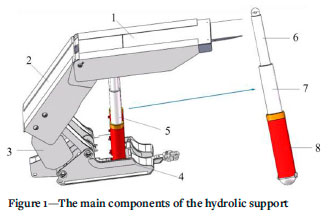
The doubly-telescopic prop is the main component in hydraulic support, as shown in Figure 1, and its strength performance test has certain requirements. The prop is filled with high-pressure emulsion in the working state, so it is necessary to understand the change of the fluid pressure inside the prop when the impact is applied.
According to Chinese standard GB 25974.2-2010, the pressure chamber of the prop is closed, during the test, and the prop shall be impacted with a weight of not less than 10 000 kg. Under the impact, the prop reaches 1.5 times the rated working pressure and the test results require that the hydraulic cylinder of the prop suffers no function failure. This standard is also in accordance with European standard EN 1804-2-2001.
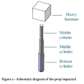
The drop weight method is a method to test the impact performance of a doubly-telescopic prop, which uses a heavy hammer falling freely from a certain height to impact the prop, and the bottom cylinder of the prop is restrained, as shown in Figure 2.
Equivalent stiffness analysis of the doubly-telescopic prop model
When the dropping hammer impacts the top of the prop, the pressure chamber of the hydraulic cylinder is locked, and the prop is regarded as an integral elastic element. In addition, the following hypotheses are proposed for the impactor and the impacted object.
> At the moment of impact, there is no rebound between the impactor and the impacted object. After contact, they are regarded as a whole and continue to move in the original direction of movement.
> In the process of impact, the energy loss due to sound and heat is very small and is neglected.
> The pipeline and seals are well sealed.
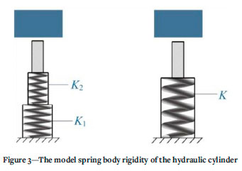
Therefore, when the hammer strikes the mobile column of the prop, both hammer and column are regarded as a single impactor bonded together and continue to move downward. The whole prop can be regarded as a spring body with equivalent stiffness K, comprising the series connection of the middle cylinder (equivalent stiffness is K2) and the bottom cylinder (equivalent stiffness K1), as shown in Figure 3.
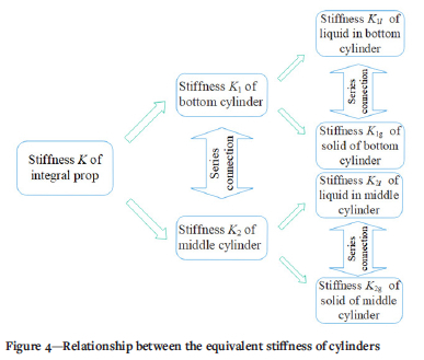
When the prop is fully extended, the hydraulic cylinder is filled with high-pressure emulsion, and the cylinder and emulsion are in the solid-liquid coupling state. The emulsion in the cylinder and the cylinder are regarded as a liquid-equivalent spring and solid-equivalent spring respectively. The equivalent stiffness of the hydraulic cylinder is equivalent to their series connection (Liu, Zhao, Zhao, 2012). The equivalent stiffness relationship of the whole prop is shown in Figure 4. According to the definition of bulk elastic modulus, the liquid equivalent stiffness of the z'th stage cylinder (i =1, 2); i =1 is the bottom cylinder and i =2 is the middle cylinder) stage cylinder is obtained as
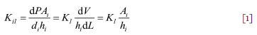
where Ai is the area of the inner circle of the ith stage cylinder (m2), di is the inner diameter of ith stage cylinder (m), hi is the height of liquid column in ith stage cylinder (m), K is the bulk modulus of 5% emulsion, and Kl = 1.8182 x 10⁹ Pa.
From the relationship between bulk modulus and elastic modulus, the equivalent stiffness of the solid of the ith stage cylinder is expressed as
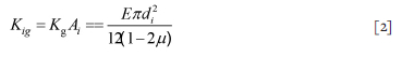
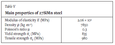
where, Kg is the bulk modulus (Pa), E is the elastic modulus of 27SiMn Steel (E = 2.06 x 10⁵ MPa), is Poisson's ratio of 27SiMn Steel (μ = 0.3).
According to Equations [1] and [2], the equivalent stiffness of the ith stage cylinder is expressed as
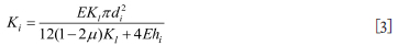
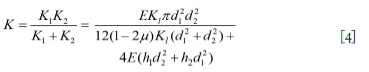
From Equation [3], the equivalent stiffness of the hydraulic cylinder is negatively correlated with the height of the liquid column in the cylinder. Finally, according to the series connection between the bottom cylinder and the middle cylinder, the equivalent stiffness of the whole prop is expressed as
Liquid pressure in the hydraulic cylinder of a double telescopic prop
According to the energy method, the dynamic load coefficient is expressed as
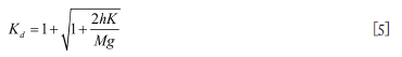
where h is the drop height of the hammer (m), g is the acceleration due to gravity (m/s2), and M is the weight of the hammer (kg).
Since the prop is regarded as an integral elastic element, the relevant formula of linear elastic body can be obtained (Equations [6] and [7]).
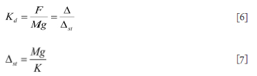
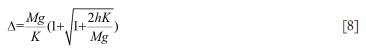
where F is the impact force (N), Δ is the displacement caused by the impact of the hammer (m), and Δst is the displacement caused by the gravitational mass of the hammer acting on the prop. From Equations [5] to [7], A can be obtained as
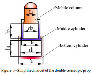
Taking the ZY8640/2550/5500 shield hydraulic support prop as an example, the simplified model is shown in Figure 5. Some parameters of the prop are shown in Table I. The mass (M) of the hammer is 28 000 kg and the drop height (h) is 400 mm.
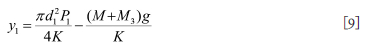
The working pressure of the ZY8640/2550/5500 shield hydraulic support's prop is 42.4 MPa. When the hydraulic pressure in the prop is P1 (working pressure), the axial downward displacement of the mobile column is y1 and the calculation is expressed as
From the conservation of energy, the related equations can be obtained as
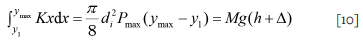
where ymax is the maximum displacement of the fluid's main vibration in the cylinder (m), and Pmax is the maximum pressure in the cylinder (Pa).
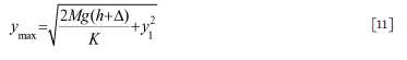
From Equation [10], ymax can be expressed as
According to the boundary condition (y = ymax sin ωt), the fluid pressure in different hydraulic cylinders can be obtained as
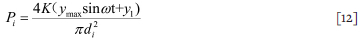
where Pi is the fluid pressure in z'th stage cylinder (Pa), ro is the main vibration angular frequency of the fluid (ω =  ), and m2 is the quality of emulsion in the middle cylinder (kg). when sinωt is taken as unity in Equation [12], and the pressure in the hydraulic cylinder is at maximum. The relevant parameters in Table I are substituted into the above formula. After calculation, the maximum liquid pressure of the middle cylinder is 172.97 MPa, and that of the bottom cylinder is 92.13 MPa.
Simulation and results
Establishment of AMESim model
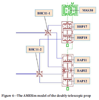
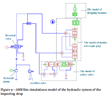
The simulation parameters for the ZY8640/2550/5500 hydraulic support prop are set according to the actual structure of the prop. The AMESim model of the prop is shown in Figure 6. In this model, BAP12 and BAP11 form a fixed bottom cylinder, BRP18 and BRP17 form a middle cylinder, and mass block MAS30 simulates the static load generated by the roof and the weight of the canopy. Other simulation elements and their parameters are shown in Table II.
The model of the safety valve as built in the AMESiM design library of hydraulic components is shown in Figure 7. In this model, the left chamber of the spool was simulated with BAP12 piston with definite volume and BAP0RT with variable volume.
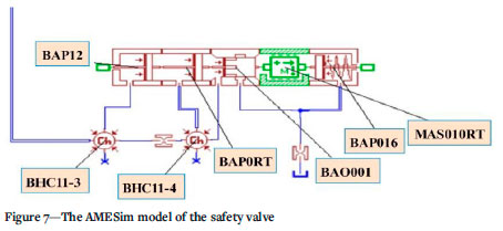
Other simulation elements and their related parameters are shown in Table III.
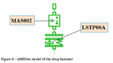
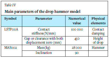
The AMESim model of the drop hammer is shown in Figure 8. In this model, the clearance in the damper LSTP00A is used to limit the drop distance of the mass block, and the appropriate contact damping parameters of the damper are set to reduce the rebound between the mass block and the prop. The relevant parameters of the drop hammer model are shown in Table IV. In addition, hydraulic pumps and motors are used from the hydraulic reservoir. The parameter of the hydraulic pump is 4000 cm3 per revolution, and that of the motor is 1000 r/min.
Finally, the above three models are connected, and the whole AMESim model is shown in Figure 9.
AMESim simulation results
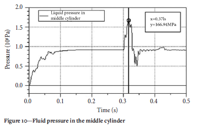
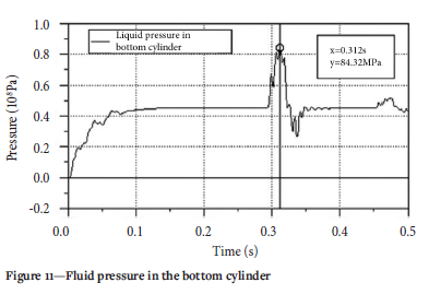
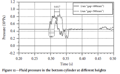
The AMESim simulation results are shown in Figures 10 and 11. The prop is in the extended phase before 0.13 seconds, and the hammer begins to contact the prop at 0.28 seconds. After the impact, the fluid pressure in the hydraulic cylinder of the prop continues to rise. The maximum fluid pressure in the bottom cylinder reaches 84.32 MPa at 0.32 seconds (see Figure 11), and that in the middle cylinder reaches 166.94 MPa at 0.37 seconds (see Figure 10). Compared with the calculation results in Equation [12] (the maximum hydraulic pressure in the middle cylinder is 172.97 MPa and that in the bottom cylinder is 92.13 MPa), the error estimation of the results for the middle cylinder is 3.61% and that for the bottom cylinder is about 8.48%. Therefore, the formula for the fluid pressure in the middle cylinder and bottom cylinder of the prop is basically correct. The hydraulic pressure peaks 5 ms later in the middle cylinder than in the bottom cylinder. In addition, the pressure in the middle cylinder is significantly higher than that in the bottom cylinder. The main reason for this is that the diameter of the middle cylinder is smaller than that of the bottom cylinder. At drop heights of 400 mm and 500 mm, the fluid pressure in the bottom cylinder is shown in Figure 12. The maximum pressure increases slightly at a drop height of 500 mm.
Establishment of doubly-telescopic prop model in Workbench
In order to obtain the maximum stress change of the hydraulic cylinder in the prop, it is necessary to perform a finite element analysis.
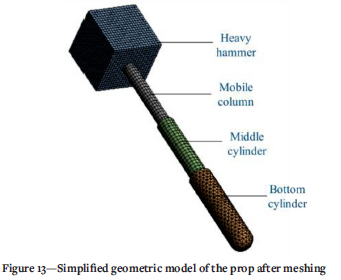
Before the finite element simulation analysis, it is necessary to simplify the geometric structure of the doubly-telescopic prop. Generally, the strength of the weld is higher than that of the cylinder, so the weld is ignored and the prop is built as a whole model. In order to make mesh division and computer calculation effective, the sealing ring and other devices are omitted. The simplified prop model includes the bottom cylinder, the middle cylinder, and the mobile column (Yang et al., 2020). This simplification affects only the analysis of local stress, and has little effect on the load distribution analysis of the whole structure. The simplified geometric model of the prop after meshing is shown in Figure 13.
Results offinite element simulation
The cylinder block of the prop is made of 27SiMn high-strength steel, and its main properties are shown in Table V. Then, the material is added to the Workbench's material library.
Transient dynamics simulation of the prop model is carried out in Workbench. The bottom surface of the bottom cylinder is fixed and constrained. The surface load of Equation [12] is applied to the inner surface of the middle cylinder and bottom cylinder, which realizes the pressure setting in the hydraulic cylinder of the prop. The solution time is set to 30 ms.
Through the simulation solution, the stress and strain cloud diagrams of the prop under the impact load of the hammer are obtained, as shown in Figures 14 and 15. After the impact on the mobile column of the prop, the pressure in the middle cylinder increases rapidly and acts on the bottom cylinder. It can be seen from Figures 14 and 15 that the overall stress on the middle cylinder is relatively large, and the maximum stress and maximum strain are located in the middle cylinder near the bottom cylinder. The maximum stress is 621.17 MPa, and both hydraulic cylinders are in a safe state.
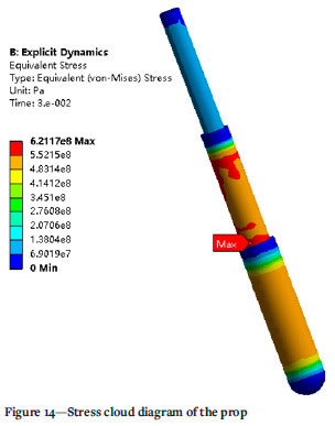
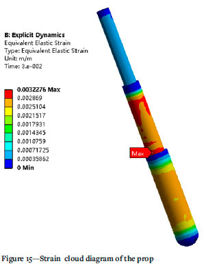
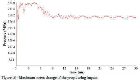
Figure 16 shows the maximum stress change on the prop during impact. The stress of the prop increases sharply and fluctuates rapidly, and is in a steady state with slight fluctuations after 13 ms.
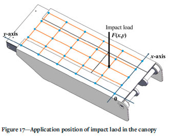
In actual working conditions, the impact load usually acts directly on the canopy of the hydraulic support, and the position of the applied load point has different effects on the prop. Taking the width of the canopy as the x-axis direction and the length direction as the y-axis direction, F(x,y) represents the position of impact load. The position of the load on the canopy is shown in Figure 17.
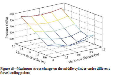
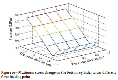
As the impact load moves towards the front of the canopy (y-axis), the maximum stress of the middle cylinder first decreases and then increases, and when the impact load acts on both sides of the top beam (x-axis), the stress on the middle cylinder increases slightly (see Figure 18). The change in maximum stress on the bottom cylinder in the y-axis direction is the same as that of the middle cylinder. There is no change in the x-axis direction with the movement of the impact load point (Figure 19).
Conclusion and discussion
In this paper, the hydraulic support prop under impact load is theoretically calculated and simulated. By modelling the hydraulic circuit of the impacted prop in AMESim, the curve of the fluid pressure in the hydraulic cylinder of the prop is obtained. Finite element simulation analysis of the hydraulic support prop in ANSYS Workbench software is used to obtain the stress and strain cloud diagrams of the prop.
> According to the theory of solid-liquid coupling and spring series connection, the relationship between the stiffness of each component of the prop is discussed. The equivalent stiffness of the hydraulic cylinder is found to be negatively related to the height of the fluid column in the cylinder, and the equivalent stiffness theory of the doubly-telescopic prop is established. The maximum pressure of emulsion in hydraulic cylinder under impact is obtained by energy conservation. It provides an effective calculation method to estimate the pressure in the hydraulic cylinder of the prop under impact load.
> Under impact loading, the fluid pressure in the hydraulic cylinder of the prop increases and decreases rapidly, and the results show that the emulsion pressure in the middle cylinder is significantly higher than that in the bottom cylinder. The AMESim prop model provides reference and guidance for the construction of a test-bed for dynamic load testing of double-telescopic props.
> Through the Workbench simulation analysis, it was found that the force on the middle cylinder of the prop under impact load is far greater than that on the bottom cylinder. The maximum stress point of the middle cylinder is located near the bottom cylinder. Therefore, in the structural design of doubly-telescopic props, more consideration should be given to the material properties of the middle cylinder, and the wall thickness of the middle cylinder should be increased if necessary. When the impact load is applied to different positions on the canopy, the maximum stress on the middle and bottom cylinders first decreases and then increases in the y-axis direction, and shows no obvious change in the x-axis direction. Installation of hydraulic supports so as to avoid impact on the front end of the canopy is therefore of great significance to prevent the prop from being damaged due to insufficient strength.
This paper adopts a simplified simulation method. The impact problem involves the solid-liquid coupling problem, but it is not simply involve mixing the solid and liquid together for impact analysis, but is also mainly related to the characteristics of a large-flow safety valve. The next step is the integrated analysis of solid-liquid coupling and large-flow safety valve in a joint simulation, so that the results are more accurate. In addition, there is still a certain gap between the impact results by computer simulation and those from a prop test-bed. In the future, it will be necessary to design the prop test-bed to accommodate the impact on double-telescopic props in different ways.
Acknowledgments
This work is supported by Open Fund of State Key Laboratory of Coal Resources and Safe Mining (Grant No. SKLCRSM21KFA12).
References
Ardehjani, E.A., Ataei, M., and Rafiee, R. 2020. Estimation of first and periodic roof weighting effect interval in mechanized longwall mining using numerical modeling. International Journal of Geomechanics, vol. 20, no. 2. http://dx.doi.org/10.1061/(ASCE)GM. 1943-5622.0001532 [ Links ]
Boutrid, A., Djouamaa, M.C., Chettibi, M., Bouhedja, A., and Talhi, K. 2016, Design of a model powered support system in Kenadsa mine (Algeria). Journal of Mining Science, vol. 52, no. 1. pp. 78-86. http://dx.doi.org/10.1134/S1062739116010150 [ Links ]
Cao, L.M., Sun, S.J., Zhang, Y.Z., Guo, H., and Zhang, Z. 2018. The research on characteristics of hydraulic support advancing control system in coal mining face. Wireless Personal Communications, vol. 102, no. 4. pp. 2667-2680. http://dx.doi.org/10.1007/s11277-018-5294-4 [ Links ]
Chinese Coal Industry Standard GB 25974. 2-2010. Hydraulic support for coal mines - Part 2: Technical conditions of prop and jack. 2010. https://std.samr.gov.cn/gb/search/gbDetailed?id=71F772D7DC66D3A7E05397BE0A0AB82A [ Links ]
Chinese Coal Industry Standard MT 313-1992, The technical condition of hydraulic support prop, 1992. https://std.samr.gov.cn/hb/search/stdHBDetailed?id=8B1827F16592BB19E05397BE0A0AB44A [ Links ]
European standard EN 1804-2-2001. Machines for underground mines - Safety requirements for hydraulic powered roof supports - Part 2: Power set legs and rams, 2001. https://standards.cencenelec.eu/dyn/www/f?p=CEN:110:0::::FSP_PROJECT,FSP_ORG_ID:66119,6177&cs=1326821640B81E203D87F944FE8BD46E6 [ Links ]
Jasiulek, D., Bartoszek, S., Perutka, K., Korshunov, A., Jagoda, J., and Plonka, M. 2019. Shield support monitoring system-operation during the support setting. Acta Montanistica Slovaca, vol. 24, no. 4. pp. 391-401. [ Links ]
Klishin, V.I. and Tarasik, T.M. 2001. Stand tests of hydraulic props in dynamic loads. Journal of Mining Science, vol. 37, no. 1. pp. 77-84. http://dx.doi.org/10.1023/A:1016788903660 [ Links ]
Liang, L.C., Tian, J.J., Zheng, H., and Jiao, S.J. 2015. A study on force transmission in a hydraulic support under impact loading on its canopy beam. Journal of the China Coal Society, vol. 40, no. 11. pp. 2522-2527. http://dx.doi.org/10.13225/j.cnki.jccs.2015.7021 [ Links ]
Liu, X.K., Zhao, Z.H., and Zhao, R. 2012. Study on dynamic features of leg applied to hydraulic powered support under bumping load. Coal Science and Technology, vol. 40, no. 12. pp. 66-70. http://dx.doi.org/10 [ Links ]
Meng, Z.S., Zhang, S., Xie, Y.Y., and Zeng, Q.L. 2020. Attitude adjustment of backfilling support based on mechanical-hydraulic co-simulation. International Journal of Simulation Modelling, vol. 19, no. 3. pp. 399-409. http://dx.doi.org/10.2507/IJSIMM19-3-520 [ Links ]
Prusek, S., Plonka, M., and Walentek, A. 2016. Applying the ground reaction curve concept to the assessment of shield support performance in longwall faces. Arabian Journal of Geosciences, vol. 9, no. 3. http://dx.doi.org/10.1007/s12517-015-2171-2 [ Links ]
Pytlik, A. 2015. Process characteristics of hydraulic legs equipped with safety valves at dynamic load caused by mining tremor. Archives of Mining Sciences, vol. 60, no. 2. pp. 595-612. http://dx.doi.org/10.1515/amsc-2015-0039 [ Links ]
Singh, G.S.P. and Singh, U.K. 2009. A numerical modeling approach for assessment of progressive caving of strata and performance of hydraulic powered support in longwall workings. Computers and Geotechnics, vol. 36, no. 7. pp. 1142-1156. http://dx.doi.org/10.1016/j.compgeo.2009.05.001 [ Links ]
Singh, G.S.P. and Singh, U.K. 2010. Prediction of caving behavior of strata and optimum rating of hydraulic powered support for longwall workings. International Journal of Rock Mechanics and Mining Sciences, vol. 47, no. 1. pp. 1-16. http://dx.doi.org/10.1016/j.ijrmms.2009.09.001 [ Links ]
Szurgacz, D. and Brodny, J. 2018. Analysis of load of a powered roof support's hydraulic leg. Proceedings of the 18th Conference of PhD Students and Young Scientists - Interdisciplinary Topics in Mining and Geology, Szklarska Poreba. http://dx.doi.org/10.1051/e3sconf/20187100002 [ Links ]
Szurgacz, D. and Brodny, J. 2019. Analysis of the influence of dynamic load on the work parameters of a powered roof support's hydraulic leg. Sustainability, vol. 11, no. 9. http://dx.doi.org/10.3390/su11092570 [ Links ]
Trueman, R., Lyman, G., and Cocker, A. 2009. Longwall roof control through a fundamental understanding of shield-strata interaction. International Journal of Rock Mechanics and Mining Sciences, vol. 46, no. 2. pp. 371-380. http://dx.doi.org/10.1016/j.ijrmms.2008.07.003 [ Links ]
Verma, A.K. and Deb, D. 2013. Numerical analysis of an interaction between hydraulic-powered support and surrounding rock strata. International Journal of Geomechanics, vol. 13, no. 2. pp. 181-192. http://dx.doi.org/10.1061/(ASCE)GM.1943-5622.0000190 [ Links ]
Wang, J., Ning, J., Jiang, L., Jiang, J.Q., and Bu, T. 2018. Structural characteristics of strata overlying of a fully mechanized longwall face: a case study. Journal of the Southern African Institute of Mining and Metallurgy, vol. 118, no. 11. pp. 1195-1204. http://dx.doi.org/10.17159/2411-9717/2018/v118n11a10 [ Links ]
Wang, X.W., Yang, Z.J., Feng, J.L., and Liu, H.J. 2013. Stress analysis and stability analysis on doubly-telescopic prop of hydraulic support. Engineering Failure Analysis, vol. 32. pp. 274-282. http://dx.doi.org/10.1016/j.engfailanal.2013.04.006 [ Links ]
Witek, M. and Prusek, S. 2016. Numerical calculations of shield support stress based on laboratory test results. Computers and Geotechnics, vol. 72. pp. 74-88. http://dx.doi.org/10.1016/j.compgeo.2015.11.007 [ Links ]
Yang, Z.K., Sun, Z.Y., Jiang, S.B., Mao, Q.H., Liu, P., and Xu, C.Z. 2020. Structural analysis on impact-mechanical properties of ultra-high hydraulic support. International Journal of Simulation Modelling, vol. 19, no. 1. pp. 17-28. http://dx.doi.org/10.2507/IJSIMM19-1-498 [ Links ]
Zeng, Q.L., Meng, Z.S., Wan, L.R., and Wang, C.L. 2018. Analysis on force transmission characteristics of two-legged shield support under impact loading. Shock and Vibration, vol. 2018. http://dx.doi.org/10.1155/2018/3854684 [ Links ]
Zhao, X.H., Li, F.Y., Liu, Y., and Fan, Y.J. 2015. Fatigue behavior of a box-type welded structure of hydraulic support used in coal mine. Materials, vol. 8, no. 10. pp. 6609-6622. http://dx.doi.org/10.3390/ma8105325 [ Links ]
 Correspondence:
X. Yang
Email: cumtb_yx@126.com
Received: 15 Mar. 2021
Revised: 17 May 2022
Accepted: 2 Jun. 2022
Published: July 2022

