


Services on Demand
Article
 English (pdf)
 Article in xml format
 Article references
Indicators

Related links
-
 Cited by Google
 -
 Similars in Google
Share

 Permalink
Journal of the Southern African Institute of Mining and Metallurgy
On-line version ISSN 2411-9717
Print version ISSN 2225-6253
J. S. Afr. Inst. Min. Metall. vol.122 n.6 Johannesburg Jun. 2022
http://dx.doi.org/10.17159/2411-9717/1787/2022
TAILINGS EDITION
http://dx.doi.org/10.17159/2411-9717/1787/2022
A limit equilibrium approach to the use of stability bunds in the design of HDPE-lined tailings storage facilities
J.D. VisagieI; T. BezuidenhoutII
ISRK Consulting (Pty) Ltd, Johannesburg, South Africa
IISRK Consulting (Pty) Ltd, Cape Town, South Africa
SYNOPSIS
In recent years the requirements for a barrier system between the waste body of tailings storage facilities (TSFs) and the natural ground (NG) has necessitated the use of HDPE-lined TSFs in South Africa and other countries. The addition of an HDPE liner creates an interface between, inter alia, the tailings and surrounding soils on the footprint of the TSF. It is known that low-strength materials beneath slopes can cause slope instability. One method which can theoretically mitigate this instability of a lined TSF is the addition of stability bunds along the footprint of the TSF. Altering the profile of the footprint to include slope changes which oppose the direction of the failure creates passive slices in a limit equilibrium analysis. The passive slices actively oppose the movement of active slices, resisting the mobilization of tailings, thus greater active slice forces are required to develop a failure surface running along the liner interface. Two scenarios are presented and compared. The first scenario retains the ground profile unaltered and the second scenario includes stability bunds along the ground profile. An in-depth assessment is made of the interslice forces and the interface shear stresses for each scenario. The theoretical background is discussed in greater detail to determine the mechanisms of reinforcement provided by the bunds.
Keywords: TSF design, HDPE lining, stability bunds, limit equilibrium approach.
Introduction
In recent years the requirements for a barrier system between the waste body of a tailings storage facility (TSF) and the natural ground (NG) has necessitated the use of HDPE-lined TSFs. As specified in Government Notice R636 of the National Norms and Standards for the Assessment of Waste to Landfill, (South Africa, 2013), material classified as a Type 1 to 4 waste requires the inclusion of a Type A to D landfill containment barrier. Landfill containment barrier classes A to C specifically require the inclusion of an HDPE geomembrane in the barrier system.
By introducing a geomembrane along the natural ground surface at the base of a TSF, a weak layer is created at the interface between the geomembrane and the surrounding materials. The failure plane, as determined from stability analyses, is naturally inclined towards the weak layers as these provide less resistance to shear failure. This has major implications for the overall stability of the system.
With the arrival of the Global Industry Standards on Tailings Management (GISTM), more emphasis has been placed on safety with regard to TSFs. In order to conform to the requirements of GISTM, new innovative ways need to be explored to manage the stability and safety of TSFs.
One such method to improve the stability of a TSF is to alter the failure plane by including stability bunds along the interface between the tailings and geomembrane to improve the global factor of safety (FoS). A FoS can simply be defined as the ratio between the shear strength of the soil resisting movement and the shear stress applied to the slip surface by the active slices. This is fundamental in understanding the benefit of stability bunds.
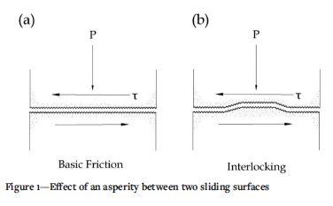
The basic principle behind the stability bund can be thought of conceptually as an asperity between two shearing surfaces, as shown in Figure 1. A planar discontinuity will yield a frictional resistance proportional to the base-normal stress (Figure 1a). With irregularities in the form of an asperity, additional work is required to overcome the interlocking effect, either by sliding over or shearing off the asperity, as shown in Figure 1b. These irregularities control deformation behaviour by either causing dilation in the adjacent material (riding-over) or shearing horizontally through the asperity along the shear direction (Kwon, Baak, and Cho, 2009).
It should be noted that all symbols are described in the Nomenclature section at the end of the paper. To demonstrate the global improvement to the FoS, two limit equilibrium (LE) analyses are compared using the Morgenstern and Price (1965) method. For the first scenario the basin of the TSF was kept unaltered while in the second scenario stability bunds were included along the interface. To further explain the impact of interslice forces, a comparison is made between the Morgenstern and Price method and the ordinary or Fellenius method, which does not take interslice forces into account. Specific attention is given to the interslice force mechanics from a theoretical and LE perspective. The addition of computer-assisted graphical representation of the slice data allows users to interrogate the results of the LE analyses in more detail.
Theoretical background
Interslice force mechanics
Slope failure, or the downslope movement of soil, rock, or tailings masses, occurs as a result of shear failure at the boundaries of the sliding mass (Eid et al., 2006). There are numerous types of failure mode which could occur, of which the most common are either rotational or translational failure modes, or a combination of the two referred to as compound slips. As these are very basic failure modes and are not necessarily representative of actual conditions, it is imperative that all possible modes of failure be checked to avoid over-estimating the FoS of the system.
Translational sliding modes are commonly subdivided into three categories, namely slab-sheet, block, and wedge slide. Residual shear strength is mobilized in soils when sliding through a pre-existing failure surface, as a result of low shear strength at the base. Heterogeneity located beneath the slope surface in the form of a stronger material underlain by a weaker material creates a planar shear surface and predominantly translational slide movement. With the presence of an interface between a geomembrane and the tailings mass, translation along the base with a linear or rotational back-surface failure is most likely (Qian, Koerner, and Gray, 2003). The tensile strength of the geomembrane can be deemed negligible as it is nominal in relation to the shear stress associated with the large failure mass. It is important that designers fundamentally assess the interface effects on the structure. Thus, accurate material-specific interface shear strengths of the various interfaces are necessary.
For translational stability evaluation it is quite appropriate to use block LE techniques employing wedges or a planar configuration in which the weakest layers are known or can be estimated. A two-wedge method was developed by Qian, Koerner, and Gray (2003) as a piecewise linear LE approach to analyse possible block movements along a geomembrane in landfills. This method can be used to analyse translational slope failure in a TSF underlain with a liner. Figure 2 shows a simplified cross-section of a TSF slope, displaying a two-wedge system for analysing translational failure. It should be noted that care must be exercised when using this method with regard to the location of the failure surface during preliminary design.
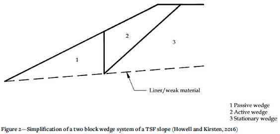
In Figure 2, zone 1 acts as a passive wedge resisting the downward movement of zone 2, which acts is the active wedge. The lateral movement of the active wedge is a result of gravitational movement of the soil mass. Zone 3 is assumed to act as a stationary wedge and is held in place by force equilibrium. Translational movement is as a result of the active wedge driving the passive wedge laterally along the failure plane. The frictional resistance along the failure plane counteracts the effects of deformation. The free body diagrams of the active and passive wedges are presented in Figure 3.
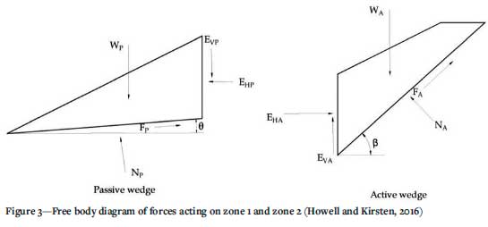
With the objective of calculating the contribution to shear strength, while maintaining equilibrium, the static force equilibrium equations can be derived from the parameters presented in Figure 3. For brevity, the derivation is not shown; however, the equations for normal forces acting at the base of the passive and active wedge and inter-wedge horizontal forces are shown below in Equations 1 to 4.
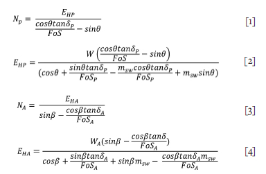
Equation [1] to Equation [4], together with the equality EHP = EHA, show the net resistance. This expression is best solved with the aid of a spreadsheet to test the parameters. This model is very powerful in promoting understanding of the engineering processes involved. Cohesion and tension in the liner can easily be calculated by adding a term to Equation [4] (Howell and Kirsten, 2016). Design calculations can be carried out quickly and efficiently to evaluate the shear strength gain by introducing a stability bund into the two-slice model, as will be shown later. More sophisticated numerical modelling can be conducted once the fundamental design is understood.
Limit equilibrium
General limit equilibrium (GLE) formulation
The general limit equilibrium (GLE) equations were developed by Fredlund at the University of Saskatchewan in the 1970s (Fredlund and Krahn, 1977; Fredlund, Krahn, and Pufahl, 1981). The GLE equations consist of two FoS equations, with respect to moment equilibrium (Fm) and force equilibrium (Ff), and allow for a range of interslice shear force directions.
Initially, LE equations were developed for base-normal forces primarily influenced by gravity, while disregarding the impact of normal and shear forces acting on the sides of the slices. Methods have since been developed which consider interslice forces. Interslice shear forces in the GLE method are determined through Equation [5], developed by Morgenstern and Price (1965).

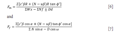
The Morgernstern and Price (1965) method allows for f(x) to be defined by the user, while other methods assume a fixed function to describe the ratio between normal and shear interslice forces. Equations [6] and [7] present the GLE FoS equations with regard to moment equilibrium and force equilibrium, respectively.
The key variable in both FoS equations is the normal stress at the base of each of the slices, determined through satisfying vertical force equilibrium. Utilizing GLE formulation, the basenormal force is determined through Equation [8].
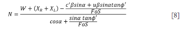
As can be seen in Equation [8], the base-normal forces are dependent on interslice shear forces. The value of N is therefore sensitive to the method, as well as the function used to define the interslice shear forces. Calculating the base-normal forces is an iterative process as the equation is dependent on the global FoS of the system. The denominator in Equation [8] is often referred to as ma and will be referred to as such in the remainder of this paper.
Morgenstern and Price (1965) method
A mathematically more rigorous method was selected for this study to account for the interslice shear and normal forces, the complex geometry of the basin, and a composite slip surface. Simpler methods do not all consider the impact of interslice forces and do not satisfy both moment and force equilibrium. The Morgenstern and Price method was used in this study for the following reasons:
> Both moment equilibrium and force equilibrium are satisfied
> Both interslice normal and shear forces are considered
> The interslice force function can utilize user-defined functions to determine the ratio between interslice normal and shear forces.
A constant interslice force function specified in the Morgenstern and Price method corresponds with the Spencer method. For the purposes of this paper a half-sine function was specified to define the ratio between normal and shear interslice forces as it concentrates the interslice shear forces towards the centre of the sliding mass, where the focus of the study lies.
Ordinary or Fellenius method
To define the effect that interslice forces have on the normal and shear stresses of each slice the ordinary or Fellenius method will be used as a baseline comparison against the Morgenstern and Price method, as interslice forces are neglected. The values determined using the ordinary or Fellenius method considers only gravitational forces in determining the normal force at the base of the slices. As a result, the equation for the base-normal forces differs from that of GLE formulation, as shown in Equation [9].

The variation between the normal forces determined by the ordinary/Fellenius method and the GLE formulation can then be ascribed to the presence or absence of interslice forces.
Slip surfaces
For a circular slip surface, moment equilibrium is independent of interslice shear forces while force equilibrium is sensitive to interslice shear forces. For a planar slip surface, force equilibrium is independent of interslice shear forces while moment equilibrium is sensitive to interslice shear forces.
As the problem is defined by the existence of a weak layer or plane, and is in essense considering the stability of a slope, both moment and force equilibrium are sensitive to interslice shear forces. A composite slip surface was considered as it acts as a combination of other standard slip surface shapes. As the Morgenstern-Price method is based on GLE formulation, it is not restricted by the shape of the slip surface.
Limitations
LE analyses are based purely on statics and do not necessarily give an accurate representation of actual stresses and displacements in the system. This is due to the fundamental assumptions which have to be made to provide a reasonable global FoS as stated by Krahn (2003), namely:
> The forces acting on each slice have to be calculated to ensure that force equilibrium (Ff) is satisfied
> The forces acting on each slice have to be calculated to provide a single FoS for each of the slices and the global system.
The overall FoS only provides a measure of the average stress mobilized in the slope (Morgenstern and Sangrey, 1978); however, it can still be considered realistic as the local irregularities are smoothed out as the driving forces and base resisting forces are integrated into the analysis (Krahn, 2003).
While LE methods are not capable of providing detailed stress, strain, and deformation outputs, they can be beneficial when used as a tool to understand the nature and mechanisms of failure. Howell and Kirsten (2016) highlighted two key benefits of LE:
> It forces the user into inductive (as opposed to deductive) reasoning by asking what the mechanism of failure could be
> It requires the calculation of basic first-principle forces and counter forces.
An added benefit to using LE is that it has been utilized for determining FoS for many years. As a result, it has been calibrated through experience and observations, which cannot be said for newer methods (Krahn, 2003).
Analysis
Limit equilibrium analysis
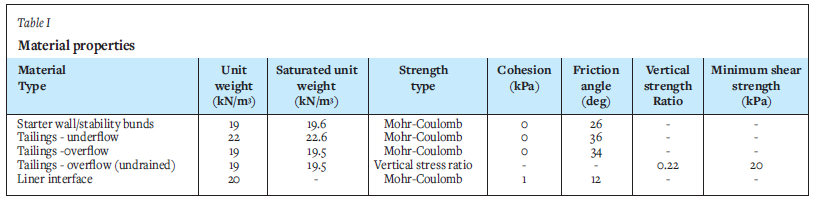
Initial LE analyses were completed for two scenarios to determine the overall impact of stability bunds along the weak layer. For scenario 1, the basin of the TSF remained unaltered, while in scenario 2, stability bunds were included along the basin of the TSF altering the path of the weak plane so as to run over the stability bunds. An undrained analysis was considered for the LE analyses and was done using Rocscience Slide2 software (Rocscience, 2020). The basic geometries of the models is presented in Figure 4. The material properties used in the analyses are presented in Table I.
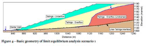
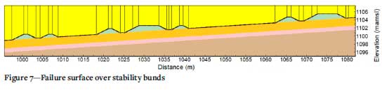
The liner interface considered the lower friction angle obtained between the liner and the tailings, and the liner and the foundation material. The results from scenario 1 and scenario 2 are presented in Figure 5 and Figure 6, respectively. Figure 7 shows the path of the failure surface over the bunds in scenario 2.
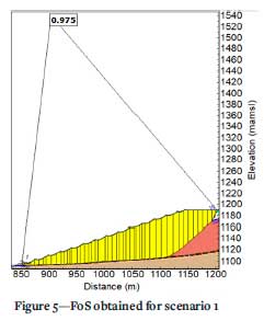
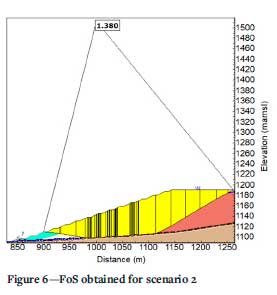
As can be seen from Figure 5, the slip surface runs along the weak layer at the base of the TSF and exits the TSF near the toe above the starter wall. Scenario 1 resulted in a global FoS of 0.975, which indicates instability. It can be seen in Figure 6 that the slip surface in scenario 2 is also inclined to run along the weak layer, following the geometry of the bunds. The overall FoS for scenario 2 was 1.38. It is clear from these examples that the addition of bunds improves the overall FoS of the slope. The mechanics of why this happens is discussed in following sections.
A significant observation regarding the two scenarios is the difference in the path of the failure surface near the toe of the TSF. Scenario 2 shows how the failure surface diverges from the weak layer and cuts through the stronger tailings material above the toe. This signifies that the resistance to shear, provided by the bunds along the weak plane, is greater than the shear resistance of the tailings material, forcing the failure surface away from the interface.
To understand why the global FoS improves, attention should be given to the slice mechanics of the failure surface. Specific attention should be given to the following:
> The inclination of the slice base
> ma as previously defined
> The base-normal stress.
Figure 8 plots the change in base topography along with ma, over the distance where the failure surface intercepts the weak layer in both scenarios 1 and 2.
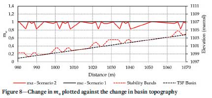
Figure 8 shows that ma is consistently lower in scenario 2 than in scenario 1. However, the average variation between the two scenarios can be explained by the iterative nature of Equation [10], with the inclusion of a FoS. What is of significance is the fluctuations of ma between the sides of the stability bunds. Consider the definition of ma as defined by Equation [10].
Considering the term 'sin α' in the second part of the equation, it is possible that a negative base inclination, relative to the direction of slippage, will cause the second part of the equation to become negative. This then decreases the value of ma which, in turn, will increase the base-normal force, increasing the FoS. The negative sign in the numerator of Equation [8] will also change to positive, as a consequence of sin α being negative, further increasing the base-normal force. The opposite applies for slices on the downstream side of the stability bunds where sin α causes base-normal stresses to decrease. This also explains the sudden decrease in the value of ma on the resisting side of the stability bund. The effect of ma on the base-normal stresses is demonstrated in Figure 9.
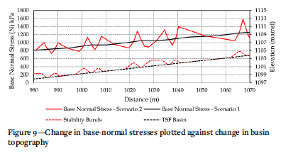
As can be seen in Figure 9, the base-normal stress on the resisting side of the bunds is significantly greater than that on the opposite side of the bund, which is consistent with the values of ma presented in Figure 8. The higher base-normal forces on the resisting side of the bunds are beneficial in resisting the active mobilization forces of the sliding mass. However, the reason for the higher normal forces has only been defined from LE formulation. To define this occurrence from a force equilibrium point of view it would be beneficial to compare the base-normal stresses obtained with the Morgenstern and Price (1965) method to that of the ordinary or Fellenius (1936) method.
For scenario 3 the same conditions were applied to the LE model as in scenario 2, however, the overall FoS was determined using the ordinary or Fellenius (1936) method. Figure 10 shows the base-normal stresses for both scenarios 2 and 3 over the distance where the slip surface intercepts the weak layer.
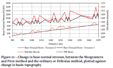
It is clear from Figure 10 that the base-normal stresses in scenario 3 do not show such significant fluctuations as in scenario 2. The change in base inclination decreases the base-normal stress on the resisting sides of the bund, the opposite of what was observed for scenario 2. The ordinary or Fellenius (1936) method considers only gravitational forces to determine the basenormal force while neglecting interslice shear forces. The variance between the base-normal forces in scenarios 2 and 3 can therefore be attributed to the presence or absence of interslice shear forces in the formulation. The FoS obtained using the ordinary or Fellenius (1936) method was 1.217, which is lower than that obtained using the Morgenstern and Price (1965) method which gives a FoS of 1.38.
Interslice force mechanics
With the inclusion of the stability bund in the passive wedge, the passive wedge in the two-block method is subdivided into slices as shown in Figure 11.
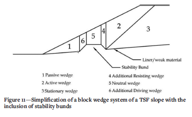
When analysing interslice force mechanics using block LE techniques the resultant forces thus act against EHA so that EHP (wedge 1) + EHP (slice 6) + EHP (slice 5) + EHP (slice 4) = EHPA to maintain static equilibrium. The free body diagrams of wedge 4 and 2 are shown in Figure 12. It is assumed that the normal and shear forces on the base and the inclined interfaces all obey the Mohr-Coulomb criterion.
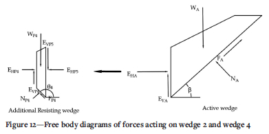
The resultant interslice shear force thus works in the resisting direction against the active wedge and EHP4 and EV4 are included in EVP5 and EHP5 so that EHP5 < EHP and EVP5 < EVP. The derivation of Equation [1] and [2] thus holds true for EHP5 and NW4. From wedge 4, a change in the base inclination results from the upstream slope of the stability bund. From Equation [1] and [2], reversing the base inclination results in the following:
> The horizontal component of the base-normal force changes direction, acting against the active movement of wedge 2
> The negative base inclination will cause a sign convention change for all terms containing sin θ. The change in sign convention will decrease the value of the denominator in Equation [2] while increasing the numerator, thus increasing EHP (the resistance against the active wedge)
> As EHP is a parameter in Equation [1], NP will also increase as a result of an increase in EHP.
Implementation
To promote maximum shear strength in resisting slope movement, stability bunds should be placed where translation takes place at the base of the slope failure (a Active wedge). It is up to the designer to scrutinise the model and find the maximum FoS, by including stability bunds within the known failure plane. Stability bunds could shift the failure plane either through the sliding mass or through the foundation material below the liner. The stability bunds will add complexity to the construction and practical considerations should be taken with regard to constructability.
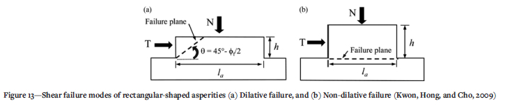
Kwon, Hong, and Cho (2010) defined a calculation procedure for shear behaviour of rectangular-shaped asperities using rigid body force equilibrium. Kwon, Baak, and Cho(2004) showed that, contrary to triangular asperities, rectangular asperities will break with a dilative failure mode. This is shown by the shear behaviour of a rectangular-shaped asperity (Figure 13).
An aspect ratio for the asperity in the form of height (h) to length (la) can be used to determine the mode of failure. Thus, the critical aspect ratio depends on the normal stress, the cohesion, and the peak friction angle (Kwon, Hong, and Cho, 2010). To promote dilative failure (Figure 13a), stability bunds should be constructed at low aspect ratios. High aspect ratios will cause failure horizontally along the shear direction (Figure 13b). The critical aspect ratio is most sensitive to the peak friction angle, proportional to the cohesion, and inversely proportional to the normal stress. The shape of a stability bund is governed by the internal friction angle of the material used in the construction. Thus, the most practical form for a stability bund would be trapezoidal (Kwon, Hong, and Cho, 2010).
The slope angles of the stability bund can be determined by a dilatant angle equal to Rankine's passive pressure 45°-(|)f/2. The angle of a failure plane to shear direction is dependent only upon the peak friction angle (Kwon, Baak, and Cho 2004).
Convergence of the FoS is sensitive to the slice base inclination. As the inclination increases, the denominator of Equation [5], also defined as ma, either increases or decreases, which can eventually lead to a value of ma computing a base-normal stress which does not satisfy the force equilibrium of the slice. This will lead to nonconvergence of the FoS, which is solved through iterative techniques. This will occur as the sides of the bunds are near vertical.
Conclusions and recommendations
Providing stability bunds along an expected weak plane will improve the FoS along that plane, when considering LE techniques. However, it is not recommended that stability be completely reliant on the provision of stability bunds, as LE techniques do not accurately define the stress state of the bunds.
Considering interslice shear mechanics, the following conclusions can be drawn.
> The horizontal component of the base-normal force on the resisting side of the stability bunds changes direction, acting against the active movement of the sliding mass.
> The negative base inclination will cause a sign convention change for all terms containing sin θ in Equation [2]. The change in sign convention will decrease the value of the denominator in Equation [2] while increasing the numerator, thus increasing resistance against the active movement of the sliding mass.
> As EHP is a parameter in Equation [1], the base-normal force on the resisting side of the stability bunds will also increase as a result of an increase in EHP.
Considering LE techniques, the following conclusions can be drawn:
> Considering Figures 5 and 6, a general improvement in the global FoS of a slope was observed with the inclusion of stability bunds along the interface between a geomembrane and the surrounding materials.
> As can be seen in Figure 8, a change in base inclination on the resisting side of the stability bunds decreases the value of ma, which essentially increases the base-normal stress, as demonstrated in Figure 9.
> Comparing the base-normal stresses acting on the stability bunds between the ordinary or Fellenius (1936) method and the Morgenstern and Price (1965) method (Figure 10) it is clear that the inclusion of interslice forces in, specifically, the Morgenstern and Price (1965) LE formulation results in a greater base-normal stress acting on the resisting side of a stability bund than on the active side.
It is recommended that in order to accurately define the stress, strain, and deformation characteristics of stability bunds, that analysis methods that consider the stress-strain relationship of the materials present be considered. Such methods would include finite element analyses or using finite element based stresses in a LE analysis.
Nomenclature
f(x) - User defined function for the distribution of interslice shear forces
λ - Percentage of the specified function used in the analysis
E - Interslice normal forces
X - Interslice shear forces
C - Effective cohesion
φ' - Effective friction angle
u - Pore -water pressure
W - Slice weight
D - Applied line load
β, R, x, f, d, ω - Geometric parameters
α - Inclination of the slice base
N, P - Base-normal force
T - Shear force
H - Height of rectangular asperity
la - Length of rectangular asperity
Θ - Base angle of passive wedge measured from horizontal
Θ4 - Base angle of passive wedge 4 measured from horizontal
β - Base angle of active wedge measured from horizontal
δP - Interface friction angle of liner components beneath passive wedge
δΑ - Interface friction angle of liner components beneath active wedge
WP - Weight of passive wedge
WP4 - Weight of resisting wedge 4
WA - Weight of active wedge
NP - Normal force acting on the bottom of passive wedge
NP4 - Normal force acting on the bottom of resisting wedge 4
NA - Normal force acting on the bottom of active wedge
FP - Frictional force acting on the bottom of passive wedge
FP4 - Frictional force acting on the bottom of resisting wedge 4
FA - Frictional force acting on the bottom of active wedge
EVP - Frictional force acting on side of passive wedge
EVP4 - Frictional force acting on side of resisting wedge 4
EVP5 - Frictional force acting on side of resisting wedge 4
EVA - Frictional force acting on side of active wedge
EHP - Normal force from active wedge acting on passive wedge
EHP4 - Normal force from resisting wedge 5 acting on passive wedge
EHP5 - Normal force from active wedge acting on resisting wedge 4
φsw - Internal friction angle of solid waste
msw - Tan tym /FoS
FoSP - Factor or safety for the passive wedge
FoSA - Factor or safety for the active wedge
φf - Rankine's strength paramter
XR - Interslice shear force on the right of the slice
XL - Interslice shear force on the left of the slice
REFERENCES
Eid, H.T., Elleboudy, A.M., Elmarsafawi, H.G., and Salama, A.G. 2006. Stability analysis and charts for slopes susceptible to translational failure. Canadian Geotechnical Journal, vol. 43, no. 12. pp. 1374-1388, [ Links ]
Fellenius, W. 1936. Calculation of stability of earth dam. Proceedings of the 2nd Congress on Large Dams, Washington, DC. vol. 4. pp. 445-462. [ Links ]
Fredlund, D.G. 1981. The relationship between limit equilibrium slope stability methods. Proceedings of the 10th International Conference on Soil Mechanics and Foundation Engineering. Belkema, Rotterdam. pp. 409-416. [ Links ]
Fredlund, D.G. and Krahn, J. 1977. Comparison of slope stability methods of analysis. Canadian Geotechnical Journal, vol. 14, no. 3. pp. 429-439. [ Links ]
Fredlund, D.G., Krahn, J., and Pufahl, D.E. 1981. The relationship between limit equilibrium slope stability methods. 10th. ICSMFE, vol. 3. pp. 409-416. [ Links ]
GEO-SLOPE. 2015. Stability Modelling with SLOPE/W, June 2015 Edition. GEO-SLOPE International Ltd., Alberta, Canada. [ Links ]
South Africa. 2013. Government Notice R636. National Norms and Standards for the Assessment of Waste to Landfill. Government Gazette, vol. 578. (36784). [ Links ]
Howell, G.C. and Kirsten, A.H. 2016. Interface shear: Towards understanding the significance in geotechnical structures. Proceedings of the First Southern African Geotechnical Conference. CRC Press. p. 267. [ Links ]
Krahn, J. 2003. The 2001 RM Hardy Lecture: The limits of limit equilibrium analyses. Canadian Geotechnical Journal, vol. 40, vol 3. pp. 643-660. [ Links ]
Kwon TH, Hong ES, Cho GC. 2010. Shear behavior of rectangular shaped asperities in rock joints. Journal of Civil Engineering,, vol. 14, no. 3. pp. 323-332. [ Links ]
Kwon, T.H., Baak, S.H., and Cho, G.C. 2004. Shear behaviour of idealized rock joints - Microscale analysis. Tunnelling and Underground Space Technology, vol. 19, no. 4-5. pp. 535-535. [ Links ]
Morgenstern, N.R. and Sangrey, D.A. 1978. Methods of stability analysis. Transportation Research Board Special Report, no. 176. https://onlinepubs.trb.org/onlinepubs/sr/sr176/176-007.pdf [ Links ]
Morgenstern, N.U. and Price, V.E. 1965. The analysis of the stability of general slip surfaces. Geotechnique, vol. 15, no. 1. pp. 79-93. [ Links ]
Qian, X., Koerner, R.M., and Gray, D.H. 2003. Translational failure analysis of landfills. Journal of Geotechnical and Geoenvironmental Engineering, vol. 129, no. 6. pp. 506-519. [ Links ]
Rocscience. 2020. Slide2 modeler, 2D Limit Equilibrium Analysis for Slopes. Rocscience Inc, Toronto, Canada. [ Links ]
Spencer, E. 1967. A method of analysis of the stability of embankments assuming parallel inter-slice forces. Geotechnique, vol. 17, no. 1. pp.11-26. [ Links ]
Stark, T.D., Williamson, T.A., and Eid, H.T. 1996. HDPE geomembrane geotextile interface shear strength. Journal of Geotechnical Engineering, vol. 122, no. 3. pp. 197-203. [ Links ]
 Correspondence:
J.D. Visagie
Email: jvisagie@srk.co.za
Received: 22 Oct. 2021
Revised: 1 Jun. 2022
Accepted: 1 Jun. 2022
Published: June 2022

