


Serviços Personalizados
Artigo
 Inglês (pdf)
 Artigo em XML
 Referências do artigo
Indicadores

Links relacionados
-
 Citado por Google
 -
 Similares em Google
Compartilhar

 Permalink
Journal of the Southern African Institute of Mining and Metallurgy
versão On-line ISSN 2411-9717
versão impressa ISSN 2225-6253
J. S. Afr. Inst. Min. Metall. vol.122 no.3 Johannesburg Mar. 2022
http://dx.doi.org/10.17159/2411-9717/1780/2022
PROFESSIONAL TECHNICAL AND SCIENTIFIC PAPERS
Rock splitting techniques for reducing undesirable cracks and fissures in rock salt blocks
M.Z. EmadI; Y. MajeedI; G. RehmanII
IDepartment of Mining Engineering, University of Engineering and Technology, Lahore, Pakistan. ORCID: M.Z. Emad: https://orcid.org/0000-0001-8537-8026; Y. Majeed: https://orcid.org/0000-0001-5479-8466
IIDepartment of Mining Engineering, Karakoram International University, Gilgit, Pakistan. G. Rehman: https://orcid.org/0000-0002-5744-3529
SYNOPSIS
Massive deposits of rock salt are mined in the Salt Range area of Pakistan. The main export products of rock salt include salt lamps, blocks, and tiles, while local consumption includes the chemical industry and domestic use. The profitable production of salt for value addition depends on the quality, size, and shape of the block. Salt processing for value addition is easier when very few cracks are present in the blocks. The current salt mining practice involves drilling and blasting, which introduces undesired fractures in the material. This paper focuses on the extraction of rock salt blocks by applying conventional cuboid-shaped block mining methods used in quarries. The techniques include wedges and feathers, expansion chemicals, and blasting with low-yield explosives. Experimental work involved both laboratory-scale and in-situ field testing. Laboratory experiments assisted with the determination of splitting force, load-deformation curves, and other rock mechanics parameters. Regression analysis proposes a relationship for the estimation of radial strain from the load in the case of the wedges and feathers method. The splitting force obtained from the laboratory tests was used to confirm the accuracy of the already published empirical relationship. The results of the laboratory as well as in-situ tests showed that the wedges and feathers technique is the most suitable method for mining rock salt blocks of the desired size, shape, while minimizing cracking.
Keywords: rock salt block, stope and pillar mining, splitting force, radial strain, Young's modulus, tensile strength, wedge and feather, expansion chemicals, controlled blasting.
Introduction
Rock salt mining is carried out by both underground mining and quarrying operations using conventional drill and blast techniques. Generally, mechanized mining techniques enable the extraction of minerals using mechanical excavators, pumping brines, and evaporation methods. However, the oldest and most popular technique for mining salt is conventional underground mining of massive deposits by the room-and-pillar method. About 40% of the salt is extracted, while the remaining 60% is left for supporting the roof (Hustrulid, 2001).
Pakistan is a rock salt producing country with an annual production of around 2.16 Mt (Department of Mines & Minerals, 2015). It is estimated that only 15% of the salt produced is export quality, while the remainder is of low value due to cracks produced during mining. Himalayan rock salt is a very popular product globally. Many items are in demand, including salt block slabs, blocks, salt lamps, tiles, and material for making medical slabs (Naz and Haleem, 2010; Rashleigh, Smith, and Roberts, 2014).
Salt exports from Pakistan could be increased if the local salt industry produces high-quality products. This requires larger, regular-shaped blocks free from undesirable micro- and macro-flaws. The industry can produce larger flawless blocks of salt by adopting unconventional mining techniques. In dimension stone quarry operations, rock splitting techniques like wedges and feathers, expansion chemicals, and controlled blasting are very common. These rock splitting methods can be adapted for underground salt deposits. The current research work includes the application of simple rock-splitting techniques for mining regular-shaped cuboid blocks of salt. The aim is to carry out a comparative analysis of the abovementioned three techniques based on block shape, size, and crack density.
Salt mining in Pakistan
Vast reserves of rock salt are located in the Salt Range Formation (Precambrian) of the northern Punjab province (Baloch et al., 2012; Shah, 1980), and salt mining and associated businesses are key elements in the local economy. The Salt Range Formation extends from Tilla Jogian in the east through Warchha to Kalabagh in the west, and is located on an active frontal thrust zone of the Himalayan mountain range. Interpretation of seismic data reveals that the offset of the basement resulted in the formation of the central Salt Range, now known as the Potwar Plateau (Leathers, 1988; Wynne, 1878). Wynne (1878) and Gee (1948) called the Salt Range the 'Saline Series' and 'Punjab Saline Series'. Asrarullah (1967) named the same rock unit the 'Salt Range Formation. The lithology of this formation includes the Sahwal Marl Member, Bhandar Kas Gypsum Member, and Billianwala Salt Member. Red marl and ferruginous content are indications of the Billianwala Salt Member (650 m thick). This is found along the southern escarpment of the Salt Range where underground salt mining takes place in Khewra, Warchha,, and Kalabagh (Shah 1980). The rock salt reserves occur in large deposits, with the Khewra mine alone containing 82 Mt (Asrarullah, 1967).
Salt Mines Khewra
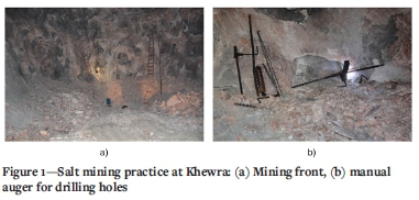
The Salt Mines Khewra are located near Khewra City (32°39'N 73°03'30"E), district Jhelum, Punjab (Batth, 2018). This is the second-largest salt mine in the world and the largest underground mine in Pakistan. The annual production of the mine is about 465 kt and the expected mine life is 350 years (Baloch et al., 2012). The rock salt deposit at Khewra forms an irregular dome-like lenticular structure. It is a massive deposit comprising many seams having a combined thickness of 150 m. Pakistan Mineral Development Corporation (PMDC) is operating the Khewra mine, which is a multilevel operation (having 17 levels) developed by regular stope and pillar mining methods. Rock salt of excellent purity occurs in different colours including semi-transparent, whitish, pink, reddish, and beef-red. In certain horizons, salt appears in the form of crystalline structures. The current mining technique is the conventional drill and blast method using black powder. Production is mainly for the chemical industry and consumer market, but some large blocks of rock salt are also extracted, which add value in the form of exports. These salt blocks are of irregular shape and low quality due to the presence of cracks from the blasting process. Fine quality crack-free blocks are used in decorative items such as salt lamps and tiles). Typical salt mining practice is depicted in in Figure 1.
Rock splitting techniques
Dimension stone mining employs wedges and feathers, expansion chemicals, controlled blasting, laser cutting, jet piercing, chain-and wire saws, and other methods for extraction of crack-free blocks. In this study, three simple, non-mechanized and low-capital methods - wedges and feathers (WF), expansion chemicals (EC), and controlled blasting (CB) - were selected for extracting crack-free, regular shaped salt blocks. The details of the chosen techniques and their application in dimension stone mining are described below:
Wedges and feathers
This is one of the most common techniques of obtaining dimension stone, which involves either drilling closely spaced holes or carving a V-shaped groove with a hand tool (chisel and hammer) followed by wedging into the rock. For the wedging action different methods have been practiced, including plugs and feathers, wooden wedges that expand when wet, and for cold climates, filling the groove or holes with water (Kirby et al., 1990; Dougan 2018). The cold temperature expands water during the night, thus inducing a split in the rock (Dunda and Kunjundzic, 1998; Changyou, 2017). According to Kirby et al. (1990), different variations of WF have been practiced since ancient times. The Egyptians used bronze plugs and feathers for mining limestone and sandstone cubes. Smith (1999) noted that many factors control the performance of the WF method, including the number and size of holes, the size of wedge and feathers, and the type of stone. The drill-holes may be coplanar to produce a clean crack.
The WF method works on the principle of transformation of vertical stress into normal or horizontal stress. Hammering of many sets of wedges and feathers in the same orientation produces a tensile splitting stress in a plane. The tensile stress produced must overcome the strength of the rock to create a splitting plane.
Expansion chemicals
Non-explosive expansion material (NEEM) is a controlled cracking method for mining good quality blocks of rock (Gholinejad and Arshadnejad, 2012). This method is safe, quiet, and free of vibrations compared to conventional techniques. It involves drilling several holes in a rock block with a fixed length, diameter, and spacing between the holes (centre-to-centre distance). NEEM slurry generates an incremental static load in the holes within 24 hours. Cracks appear between the coplanar holes if the design specifications are correct, and merge to form a clean splitting surface. It is important to adhere to the manufacturer's recommendations to achieve the desired results. In general, the closer the holes are spaced, the faster the material will crack. The results produced by NEEM are dependent on the diameter of the holes. A smaller hole diameter results in no split plane, while a very large diameter develops a blowout from the collar.
Another important parameter is the reaction time of the chemical, which ranges from 24 hours to 76 hours. A longer time affects production scheduling. The range is a function of many factors such as the type of material, hole diameter and spacing, and the temperature on-site (Hoek and Bieniawski, 1963; Konik et al., 2007; Ahn and Hu, 2015; Yu et al., 2018). According to Gomez and Mura (1984) expansion chemicals can exert a peak expansion stress of up to 11 000 psi (75 842 kN/m2). EC works similarly to WF, creating the splitting surface by the development of tensile stress. The radial force generated within the drill-holes produces high compressive stress perpendicular to the split surface, which generates cracks in the rock matrix. These cracks are not desirable, and care must be taken to minimize their formation.
Modified controlled blasting
Drilling and blasting is one of the cheapest methods (low initial and operational costs, fast production rate, and site area flexibility). Block extraction is also possible through the blasting of holes with small spacing and using a low-power explosive. The conventional blasting process creates both desirable and undesirable cracks and fissures in the rocks, while the CB method generates micro-fissures in the desired direction and reduces the development of microcracks in the remaining rock matrix (Rao et al., 1997; Bhandari and Rathore, 2006). The extraction of rock blocks using a CB has been discussed by various researchers. Olsson and Bergqvist (1996) emphasised the crack-free extraction of dimension stone by decoupling of holes and sympathetic detonation. According to Khoshrou (1996) and Ahmadinejad (2009), the propagation of cracks in the rock mass is generally controlled by the quantity of explosive charge. Detonating cord with lining is another useful technique for mining dimension stone.
The working mechanism of the CB technique for rock splitting is like that of the WF and EC methods. It involves the development of radial stresses in drill-holes due to the instantaneous production of shock waves accompanied by gas pressure. This radial force is a dynamic impact load, which is then converted to tensile stress, creating a split plane. Some of the radial stress creates a compressive stress, which leads to the development of undesirable cracks.
Experimental
Majeed et al. (2019) confirmed the quality of rock salt blocks excavated in situ through conventional quarrying techniques. The physicomechanical laboratory testing programme validated the results of block mining techniques studied. The current study envisaged a comprehensive testing programme including both laboratory-scale and in-situ field experiments to assess the selected techniques from the dimension stone industry (WF, EC, and CB). Laboratory testing on rock salt blocks paved the way for in-situ experimentation. The laboratory compression machine helped with establishing the splitting force required to produce a split plane in a rock salt block using the WF method, and also helped with the generation of rock properties data for validation. Figure 2 illustrates the entire testing scheme and a summary of the stepwise method.
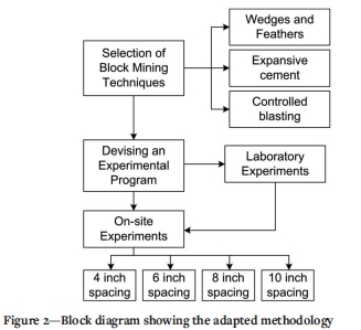
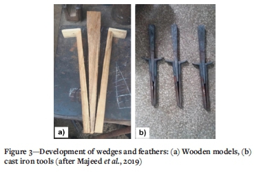
Figure 3 shows the manufacturing of wedges and feathers for this research. Each set comprises a tapered tool-metal wedge (plugs, 10 inches or 25.4 cm long), and bi-metal shims (feathers, 8 inches or 20.32 cm long). The feathers are wider at the bottom than at the top.
The ambient temperature (10-25°C) of the Khewra salt mine and laboratory conformed to the specifications the SCA-1 chemical. Gunpowder paper cartridges assisted with carrying out CB.
Laboratory-scale experiments
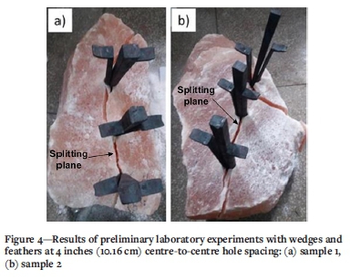
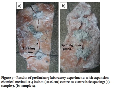
Laboratory-scale testing of WF (samples 1 and 2) and EC (samples 3 and 4) methods was carried out on rock salt blocks from the Khewra mine. Rock properties were determined in the laboratory for validation of crack formation. The CB method was not used in the laboratory for obvious reasons. For each method (QF and EC) a single row of 1 inch (2.54 cm) diameter holes with both spacing and depth of 4 inches (10.16 cm) was drilled into the boulders. The results of these experiments are shown in Figures 4 and 5. The flatter lower part is oriented along with the anticipated orientation of the splitting plane. In the WF method, the plugs were placed and the wedges hammered until the appearance of a crack along the hole. As shown in Figure 4, the technique produced a regular split line between the holes. For the EC experiments, a mixture of expansion chemical (5 kg chemical per 1.5 litres water) was poured into the pre-drilled holes within ten minutes of mixing. The boulders were then cured for a period of 24 hours. An irregular split line was formed between the holes and the boulders were split into three pieces (see Figure 5).
Determination of splitting force
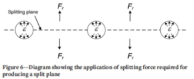
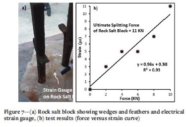
The rock splitting technique produces radial compressive stress (ar) around the drill-hole and a radial strain (s). When the drillholes are aligned to form a split plane, a splitting force (Fr) is produced perpendicular to the splitting plane (Figure 6). The radial stress is responsible for generating a crack in the rock block when it exceeds the tensile strength (a) of the material (i.e., In the first phase, a laboratory experiment on a rock salt block was designed to find the actual splitting force and strain by using the WF. For this purpose, three drill-holes of 1 inch (2.54 cm) diameter were drilled into the block at 4 inches (10.16 cm) centre-to-centre spacing up to a depth of 4 inches (10.16 cm). An electrical resistance strain gauge was fixed at the anticipated split plane approximately midway between two adjacent drillholes (Figure 7a). The prepared block was then loaded through wedges between the platens of a universal testing machine until a split plane appeared. The strain values at prefixed load intervals of 2 kN were recorded using a Vishay digital strain recorder. The test results are presented in Figure 7b, where a linear increasing relationship can be seen between splitting force and strain.
In the second phase, efforts were made to compute the force required to produce a split plane in a rock salt block indirectly, using routine rock mechanics parameters, with the help of the following empirical relationship (Atanackovic and Guran, 2000; Salmi and Hossainzadeh, 2014):

where FTis the splitting force; A is the area of splitting surface, E is the Young's modulus, and s is the strain.
The mechanical rock properties [tensile strength (a) and Young's modulus (E) were determined on prepared cylindrical rock salt samples as per ISRM suggested methods (ISRM, 1978, 1979). The area of the splitting surface (A) was acquired by considering split plane dimensions at 4, 6, 8, and 10 inches (10.16, 15.24, 20.364, cm), and 25.4 cm) centre-to-centre hole spacing. Table I outlines the input parameters required for Equation [1] along with the computed splitting force (Fr) for each block size. It is worth noting here that the splitting force of 14.4 kN (at 4 inches or 10.16 cm spacing in Table I), computed by using Equation [1], is quite close to the actual splitting force of 11 kN determined through direct experimentation (Figure 7b).
In-situ experiments
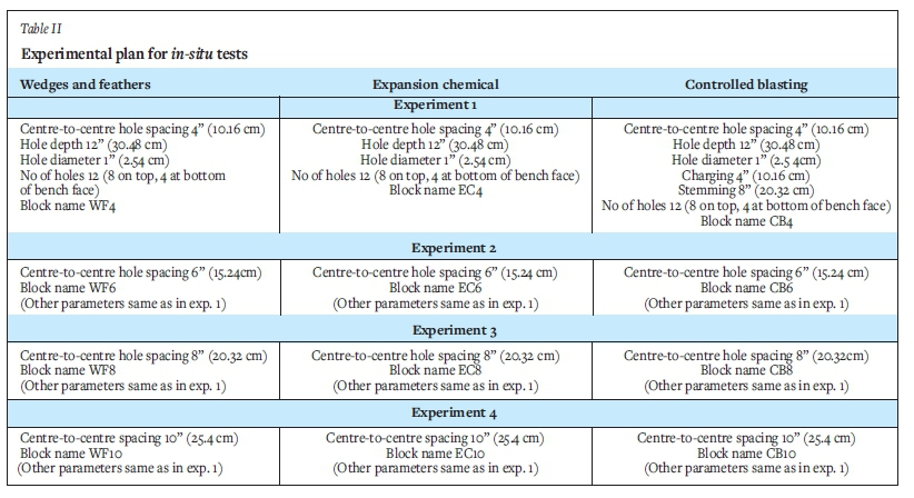
In-situ experiments were carried out at Khewra salt mines by adopting the three selected rock splitting techniques according to a pre-defisned programme as explained in Table II. For this purpose, a suitable location in the mine was selected based on the availability of a bench face (two free faces normal to each other). This was required to perform four experiments using each technique for extracting blocks of rock salt. As per plan (Table II), a total of eight holes (diameter 2.54 cm) were drilled vertically to form a square shape. Four horizontal holes were drilled from the bench face to form a square prismatic block. The inter-hole spacing at the upper face was varied at 4 inches (10.16 cm), 6 inches (15.24 cm), 8 inches (20.32 cm), and 10 inches (25.4 cm). The centre-to-centre hole spacing at the bottom of the block was kept at 4 inches (10.16 cm).
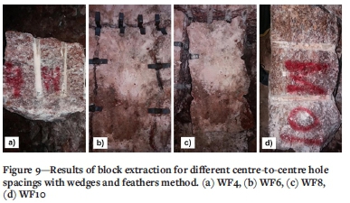
In the case of the WF rock splitting technique, four blocks of rock salt (WF4, WF6, WF8, and WF10) were extracted. The numbers 4, 6, 8, and 10 are assigned based on inter-hole spacing as per the experimental plan (Table II). Figure 8 shows the stepwise procedure adopted for block extraction. The results are shown in Figure 9. Some undesirable cracks were observed in the walls of mined-out blocks WF4 and WF6 when the inter-hole spacing was kept at 4 inches (10.16cm) and 6 inches (15.24 cm). In contrast, blocks WF8 and WF10, extracted with 8 inches (20.32 cm) and 10 inches (25.4 cm) spacing showed promising results.

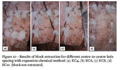
Field experiments were performed with the EC method according to the pre-defined experimental plan. In general, it was observed (Figure 10) that the EC technique produced more undesirable cracks (especially in blocks EC4 and EC6) compared to the WF method. The best result was obtained in the case of block EC8, extracted at 8 inches (20.32 cm) centre-to-centre hole spacing, while at 10 inches (25.4 cm) hole spacing the salt block (EC10) was not extractable due to the improper formation of the splitting plane. A 10 inch (25.4 cm) hole spacing is thus not practicable in the given experimental conditions.
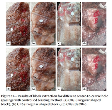
The CB method was applied by using explosive (gunpowder) paper cartridges 0.87 inches in diameter (2.21 cm), and 4 inches (10.16 cm) in length. The holes, drilled according to the experimental plan (Table II), were bottom-charged using 4-inch (10.16cm) long cartridges and primed with 2.5 ft long safety fuses. The remaining 8 inches (20.32 cm) of the holes were filled with the drill cuttings as stemming material. To reduce the explosive quantity per blast, the holes were charged alternately (one charged and one uncharged), so that one drill-hole acted as a free face for the other one. This technique produced shattered and irregular-shaped salt blocks CB4 and CB6 at inter-hole spacings of 4 inch (10.16 cm) and 6 inches (15.24). Regular shaped blocks (EC8 and EC10) with fewer undesirable cracks were obtained from 8 inch (20.32 cm) and 10 inch (25.4 cm) hole spacings. The results of the CB experiments are shown in Figure 11. The results of the field experiments performed with all three techniques are summarized in Table III.
Core quality assessment
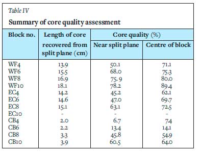
The rock salt blocks retrieved by in-situ testing (Table III) were assessed for the development of cracks along the splitting plane. The assessment involved drilling NX-sized cores and measuring rock quality along the perimeter and from the centre of the blocks. The cores obtained had both natural fractures and fresh cracks created by the three splitting techniques. The crack formation is represented by the core quality and the results are shown in Table IV. The core quality is very like the rock quality designation or RQD, and is computed by the following relationship:

Discussion
The laboratory work was conducted to develop an understanding of rock splitting mechanisms and determine the splitting force, load-deformation curve, and rock parameters (Young's modulus, tensile strength, and strain). The laboratory experiments also helped to determine the diameter, centre-to-centre spacing, and depth of holes. The preliminary laboratory experiments conducted on rock salt boulders with 1 inch (2.54 cm) diameter holes drilled at 4 inch (10.16 cm) centre-tocentre spacing showed that a regular split surface can be produced with both the WF and EC techniques. Laboratory experiments was also performed on rock salt blocks extracted by the WF4 method to determine the peak splitting force and to record the strain during splitting using an electrical resistance strain gauge (Figure 7). The experiment helped with developing a load-deformation curve and the strain along a splitting plane can be determined using the equation proposed in Figure 7b. Finally, the splitting force was also determined (Equation [1]), using simple rock mechanics parameters like area of splitting plane, Young's modulus, and strain. It was found that the value of the splitting force calculated from Equation [1] is close to the actual value found in the experiment.
The subsequent in-situ experiments showed that regular prismatic blocks can be produced by the WF technique (Figure 9). The shape and size of blocks and the split surface produced at all four centre-to-centre spacings were of good quality (Table III) with no undesirable cracks. The WF technique was found to be much better than the EC and CB methods. This is due to the controlled static radial load around the wedge and feather tools. The parametric study performed (for centre-to-centre hole spacing) with the WF method showed that blocks extracted with a hole spacing of 8 inches and 10 inches (20.32 cm and 25.4 cm) conform to the desired product. Extraction with WF is also friendlier as it produces no vibrations, dust, gases, or fly-rock. Moreover, this technique is simple, and labourers can be trained within a couple of hours.
Experiments on the extraction of blocks with expansion chemicals (Figure 10) showed that irregular cracks are produced, leading to an irregular splitting surface and unwanted fractures. The effect was prominent in blocks with smaller hole spacings (10.16 and 15.24 cm). The expansion chemicals performed much better with greater spacings but the results were not as good as with wedges and feathers. Blocks with a hole spacing of less than 6 inches (15.24 cm) contained undesirable cracks, while a spacing of 8 inches (20.326 cm) produced more regularly shaped and sized blocks. This is because a low splitting force is required to split the blocks with smaller spacing. The extra energy provided by expansion chemicals generates fractures in the blocks. A block with a hole spacing of 10 inches (25.4 cm) could not be extracted since separation from the host rock was incomplete. Many undesired cracks were found around the drill-holes. There are two issues with this technique. Firstly, it takes 24 hours before a full split surface is obtained, and secondly, the technique is sensitive to temperature. In a mining cycle, this technique is too slow compared to WF or CB. This will affect mine scheduling and mine planning.
The results of the modified CB technique (Figure 11) showed that it is an unsatisfactory technique. The blocks obtained were of irregular shape and unsuitable size. The loss of block shape and size was noticeable for blocks produced with hole spacings of 4 and 6 inches (10.16 cm and 15.24 cm). This is because a low splitting force is required to split the blocks along holes drilled with smaller spacing. The energy provided by the explosive is far more than is required for generating the splitting plane. The blocks with hole spacings of 8 and 10 inches (20.32 cm and 25.4 cm) were also irregular and improperly sized with many unwanted cracks. The failure of this technique to produce regular shaped and sized blocks is attributed to uncontrollable blasting parameters including a low-quality initiation system, inappropriate delay detonation, low-quality explosive, the intrinsic properties of rock salt, local geology, and skill of the operator. The technique can be further studied to optimize many factors before adoption to block extraction.
The core quality test results (Table IV) show that the cores drilled near the splitting plane obtained by the WF technique have a quality of 50% to 80%, followed by EC (45% to 64%), and CB techniques (6% to 60%). Core retrieved from the block centre for the WF technique has a higher core quality percentage (70% to 89%) in comparison to the EC (60% to 70%) and CB (50% to 60%) techniques. It is evident from the test results (Table IV) that WF techniques can produce higher-quality salt blocks, with minimal fractures, than the other two techniques. Furthermore, the design adopted for the wedges and feathers can be improved.
All three techniques are labour-intensive and need skilled operators to produce rock salt blocks without undesirable cracks. A comparative study is required incorporating further block extraction techniques such as laser cutting, jet piercing, and wire saw and chainsaw cutting. Economic analysis of all these techniques is also required, along with performance evaluation. An optimization study to identify the best techniques for underground salt mining is to be investigated. A salt block processor is also required by the mining industry which can cut and polish larger blocks into tiles or slabs.
Recommendations and future work
Wedge and feather techniques can be used for salt block extraction in the salt mining industry. The main recommendations are:
(1) Wedges should be prepared according to the specification of the holes (diameter and length).
(2) The feathers and wedges should be oriented along the direction of the intended split.
(3) The expansive cement must be chosen in accordance with the temperature on site.
(4) A high-resolution camera should be used for photography.
A lot of research can be carried out in the future in this field related to economic analysis, experiments with new techniques, optimization of techniques, and the design of new mechanized cutters for flawless salt block extraction. Research can be conducted on developing salt block processors to produce quality products that can be exported around the world.
Conclusions
Salt block extraction techniques are very important for the growing ornamental rock salt industry of Pakistan. A good rock salt block extraction technique can help to produce good quality exportable products. We have presented the results of laboratory and in-situ experiments using three techniques from dimension stone mining - wedge and feather (WF), expansion chemicals (EC), and controlled blasting (CB). The parameters for the in-situ experiments were determined through laboratory tests. A load-deformation curve was developed during experimentation on an actual rock salt block for the WF method. A prediction equation has been proposed for the estimation of deformation for a given value of the applied load. The actual value of the splitting force was found to be close enough to the theoretical value computed using the empirical correlation.
The in-situ experiments showed that the WF method produces regular shaped, and proper sized blocks with minimal undesirable cracks, provided an appropriate drill-hole spacing is used. A hole spacing of 8 inches (20.32 cm) and 10 inches (25.4 cm) produces good quality blocks. The blocks extracted with expansion chemicals were regularly sized and shaped, but contained some unwanted cracks. No block could be extracted with expansion chemicals for the 10-inches (25.4 cm) centre-to-centre spacing.
The CB technique produced irregular-shaped and improper-sized blocks with a good number of undesired cracks, owing to the energy provided by the explosive being far more than is required for splitting. Only with a wider drill-hole spacing was a more regular block with fewer unwanted cracks produced.
The quality of the salt blocks produced was assessed from core quality checks. Even in the worst scenario (cores from near the split plane), the test results showed that the WF technique produced the best quality blocks with a core quality value of 50% to 80%, followed by the EC technique (45% to 64%) and CB (6% to 60%).
The WF technique is promising for producing larger sized rock salt blocks. This technique can be further studied to optimize the drill-hole diameter, depth, and spacing. The production of larger blocks will enable the manufacture of good quality products.
Acknowledgements
The authors would like to acknowledge the support and assistance of the management of Salt Mines Khewra (PMDC), especially Engineer Irfan Chaudhry (Project Manager), Engineer Azghar Iqbal Khattak (Assistant Manager), and Engineer. Hafiz Muhammad Saeed (Assistant Manager) for their continued support, guidance, and dedicated help during the in-situ work. The authors are also thankful to the Department of Mining Engineering, University of Engineering, and Technology, Lahore, for facilitating this project.
References
Ahmadinejad, S. Application of stress analysis and fracture mechanics in controlled blasting for hard rock quarry mining. Proceedings of the 1st Symposium of Dimension Stone, Mahallat, Iran, 2009, [ Links ]
Ahn, C.-H. and Hu, J.W. 2015. Investigation of key parameters of rock cracking using the expansion of vermiculite material. Materials, vol. 8, no. 10. pp. 6950-6961. https://doi.org/10.3390/ma8105351 [ Links ]
Asrarullah, P. 1967. Geology of the Khewra Dome. Proceedings of 18th and 19th Combined Session of the All-Pakistan Science Conference Part III, Hyderabad, Pakistan. [ Links ]
Atanackovic, T.M. and Guran, A. 2000. Hooke's Law. Theory of Elasticity for Scientists and Engineers. Atanackovic, T.M. and Guran, A. (eds). Birkhauser, Boston, MA., Chapter 3, pp. 85-111. [ Links ]
Baloch, M.. Qureshi, A., Waheed, A., Ali, M., Ali, N., Tufail, M., and Khan, H. 2012, A study on natural radioactivity in Khewra Salt Mines, Pakistan. Journal of Radiation Research, vol. 53, no. 3. pp. 411-421. [ Links ]
Batth, U.A. 2016. Khewra Salt Mines. http://www.pmdc.gov.pk/?p=KhewraSaltMines [accessed 29 May 2018]. [ Links ]
Bhandari, S. and Rathore, S.S. 2006 . Development of macrocrack by blasting while protecting damages to remaining rock. Proceedings of the 7th International Symposium on Rock Fragmentation by Blasting (Fragblast-7). Beijing, China, Taylor & Francis. pp. 176-181 [ Links ]
Changyou, L., Jingxuan, Y., and Bin, Y. 2017, Rock-breaking mechanism and experimental analysis of confined blasting of borehole surrounding rock. International Journal of Mining Science and Technology, vol. 27, no. 5. pp. 795-801. https://doi.org/10.1016/j.ijmst.2017.07.016 [ Links ]
Dougan, D. 2004. Splitting and cutting tools. https://dondougan.homestead.com/TheProcess4_History.html [accessed 29 May 2018]. [ Links ]
Dunda, S. and Kunjundzic, T. 1998. Quarrying of dimension stone in different geological conditions. Proceedings of the 7th Mine Planning and Equipment Selection Conference, Calgary, Canada. Balkema, Rotterdam. [ Links ]
Department of Mines & Minerals. 2015. Important Minerals Occurring in Punjab. https://mnm.punjab.gov.pk/important_minerals_occurring_in_punjab#17 [ Links ]
Gee, E.R. 1945. The age of the Saline Series of the Punjab and of Kohat. Journal of National Academy of Sciences, India. Section B, vol. 14. pp. 269-310. [ Links ]
Gholinejad, M. and Arshadnejad, S. 2012. An experimental approach to determine the hole-pressure under expansion load. Journal of the Southern African Institute of Mining and Metallurgy, vol. 112. pp. 631-635. [ Links ]
Gomez, C. and Mura, T. 1984. Stresses caused by expansion chemical in borehole. Journal of Engineering Mechanics, vol. 110, no. 6. pp. 1001-1005. [ Links ]
Hoek, E. and Bieniawski, Z.T. 1963. Application of the photoelastic coating technique to the study the stress redistribution associated with plastic flow around notches. South African Mechanical Engineer, vol. 2, no. 8. pp. 222-226. [ Links ]
Hustrulid, W. A. and Bullock, .R.C. 2001. Underground Mining Methods: Engineering Fundamentals and International Case Studies. Society for Mining, Metallurgy & Exploration, Littleton, CO. [ Links ]
ISRM. 1978, Suggested methods for determining tensile strength of rock materials. International Journal of Rock Mechanics and Mining Sciences and Geomechanics Abstracts, vol. 15. pp. 99-103. [ Links ]
ISRM, 1979. Suggested methods for determining the uniaxial compressive strength and deformability of rock materials. International Journal of Rocks Mechanics and Mining Sciences and Geomechanics Abstracts, vol. 16. pp. 135-140. [ Links ]
Kirby, R.S., Withington, S., Darling, A.B., and Kilgour, F.G. 1990. Engineering in History. Dover, New York. [ Links ]
Khoshrou, S.H. 1996. Theoretical and experimental investigation of wall-control blasting methods.. http://digitool.Library.McGill.CA:80/R/?fiinc=dbin-jump-full&object_id=108801 [accessed 28 May, 2018]. [ Links ]
Konik, Z., Malolepszy, J., Roszczynialski, W., and Stok, A. 2007. Production of expansion additive to Portland cement. Journal of the European Ceramic Society, vol. 27, no. 2-3. pp. 605-609. [ Links ]
Leathers, M.R. 1988. Balanced structural cross section of the central Salt Range and Potwar Plateau of Pakistan-Shortening and overthrust deformation: Corvallis. MS thesis, Oregon State University. [ Links ]
Majeed, Y., Emad, M.Z., Rehman, G., and Arshad, M. 2019. Block extraction of Himalayan rock salt by applying conventional dimension stone quarrying techniques. Journal of Mining Science, vol. 55, no. 4. pp. 610-625. [ Links ]
Naz, H. and Haleem, D.J. 2010. Exposure to illuminated salt lamp increases 5-HT metabolism: A serotonergic perspective to its beneficial effects. Pakistan Journal of Biochemistry and Molecular Biology, vol. 43, no. 2. pp. 105-108. [ Links ]
Olsson, M. and Bergqvist, I. 1996. Crack lengths from explosives in multiple hole blasting. Proceedings of the 5th International Symposium on Rock Fragmentation by Blasting - FRAGBLAST-5, Montreal, Quebec, Canada, August 25-29, 1996. Taylor & Francis. pp. 187-191. [ Links ]
Rashleigh, R., Smith, S.M.S., and Roberts, N.J. 2014, A review of halotherapy for chronic obstructive pulmonary disease. International Journal of Chronic Obstructive Pulmonary Disease, vol. 9. pp. 239-246. doi: 10.2147/COPD.S57511 [ Links ]
Rao, K.U.M., Bhatnagar, A., Jain, D.K., and Sural, A.K. 1997. Recent Trends of Dimensional Stone Mining in India; Artisan Mining of Coal in the Garo Hills, Meghalaya Mining on a Small and Medium Scale. Practical Action Publishing, Rugby, Warwickshire, UK. pp. 235-252, [ Links ]
Salmi, E. F. and S. Hosseinzadeh, S. 2014. A further study on the mechanism of pre-splitting in mining engineering. Applied Mechanics and Materials, vol. 553. pp. 476-481. doi: doi:10.4028/www.scientific.net/amm.553476 [ Links ]
Shah, S.M.I. 1980. Records of the Geological Survey of Pakistan, Stratigraphy and economic geology of Central Salt Range. Memoirs of the Geological Survey of Pakistan, vol. 52. [ Links ]
Smith, M. 1999.Building stone, rock fill and Armourstone in construction. Engineeriig. Geology Special Publication no. 16. Geological Society. of London. pp. 188-200. [ Links ]
Wynne, A. 1878. On the geology of the Salt Range in the Punjab: India. Geological Survey Memoirs [India], no. 14. pp. 313, [ Links ]
Yu, H., Wu, L., Liu, W.V., and Pourrahimian, Y. 2018. Effects of fibers on expansion shotcrete mixtures consisting of calcium sulfoaluminate chemical, ordinary Portland chemical, and calcium sulfate. Journal of Rock Mechanics and Geotechnical Engineering, vol. 10, no. 2. pp. 212-221. doi: https://doi.org/10.1016/j.jrmge.2017.12.001 [ Links ]
 Correspondence:
M.Z. Emad
Email: zaka@uet.edu.pk
Received: 7 Oct. 2021
Revised: 8 Feb. 2022
Accepted: 9 Feb. 2022
Published: March 2022

