


Services on Demand
Article
 English (pdf)
 Article in xml format
 Article references
Indicators

Related links
-
 Cited by Google
 -
 Similars in Google
Share

 Permalink
Journal of the Southern African Institute of Mining and Metallurgy
On-line version ISSN 2411-9717
Print version ISSN 2225-6253
J. S. Afr. Inst. Min. Metall. vol.122 n.3 Johannesburg Mar. 2022
http://dx.doi.org/10.17159/2411-9717/480/2022
PROFESSIONAL TECHNICAL AND SCIENTIFIC PAPERS
Void filling and water sealing in a decline in the Kalahari Manganese Field
I. Serepa; N.C. Steenkamp
Worley
SYNOPSIS
Investigations were conducted to determine the condition and stability of the existing decline at a mine in the Kalahari Manganese Field, Northern Cape Province, South Africa. During the inspection of the decline, voids were identified behind the concrete lining on the hangingwall and sidewalls over a total linear distance of 230 m. The voids did not provide confinement and, as a result, self-mining was occurring behind the lining. Water was flowing into the decline, over a total linear distance of 100 m, at areas where the decline intersected incompetent rock units, causing softening of the concrete lining and deterioration of the surrounding rock mass. Further damage to the concrete lining was caused by expansion and contraction of the wet red clay unit.
Remedial work comprised void filling and water sealing to prevent further deterioration of the decline and ensure that it remained operable for the remainder of the life of mine. Void filling was accomplished by drilling rows of holes along the decline to access the voids and filling the voids with foam. This was followed by the sealing with polymer fluids. Telescopic pipes were also installed to allow water to drain off.
A visual inspection was conducted and check-holes were drilled to assess the quality of the remedial work. The void filling material had penetrated cracks in the concrete lining, and areas where voids were intersected by check-holes were re-filled. Additional holes were drilled to re-seal areas that were still wet. The remedial work was completed successfully, as all voids were filled and stability achieved without compromising the concrete lining. The ingress of groundwater was also reduced to some residual dampness.
Keywords: ground support, decline, concrete lining, void filling, sealing.
Introduction
Background
The decline under study was developed during the late 1970s and commissioned in the early 1980s. It is currently the primary means of accessing the mine. The decline intersects unconsolidated sediments and highly weathered material before entering competent rock. The condition of the decline in the upper portion deteriorated over the last 30 years and remedial action needed to be taken to ensure safe use for the remainder of the life of mine. The decline has a total length of 770 m. The first 240 m from the portal is supported with steel arches spaced at 1 m and 0.50 m thick concrete slabs. The remainder of the decline is located in hard rock and supported with rockbolts.
A variety of investigations, including in-decline geotechnical mapping and a surface electrical resistivity imaging (ERI) survey were conducted to determine the factors affecting the stability of the decline. Voids were identified behind the concrete lining. The voids occurred on the hangingwall and sidewalls from approximately 10 m to 240 m into the decline. The extent of the voids was determined using a borehole camera. The width of the voids varied from 0.3 m to 1 m and their length was limited to 1 m, which is the spacing between the steel arches. No voids were identified in areas where the decline is located in hard rock.
Water ingress into the decline was observed from 120 m to 220 m where the decline intersects calcrete, gravel, and red clay units. The water had deteriorated the rock mass and washed out fines from the calcrete, unconsolidated gravel units, and highly weathered tillite. In addition, the water caused softening of the concrete lining and deterioration along the red clays due to the expansion and contraction of the wet clay. It was suggested that the flow of groundwater can initiate void formation through self-mining and that the size of the voids would increase over time. A secondary problem was that during winter the water on the roadway froze due to wind chill. This caused the decline to be closed until it was safe to access again.
Recommendations were made to prevent further damage to the decline. These included filling all voids with material that would provide confinement without compromising the integrity of the concrete lining and creating an impenetrable curtain around the decline to seal the water. The aim of the project therefore was to stabilize the ground conditions behind the concrete lining of the decline and to effectively manage the groundwater ingress into the decline.
Location of the project
The mine is located within the Kalahari Manganese Field (KMF). The KMF is located 60 km northwest of Kuruman in the Northern Cape Province of South Africa (Figure 1) and hosts 1350 Mt of manganese ore resources, making it the largest manganese ore basin in the world in terms of ore resources (Kuleshov, 2012).

Geological setting
The KMF is the largest known preserved land-based manganese deposit on Earth. It has been traced by boreholes and mining works over 15 km in the longitudinal direction and 35 to 40 km in the meridional direction (Kuleshov, 2012). The KMF is hosted by the Transvaal Supergroup in the Griqualand West area. The Transvaal Supergroup is overlain by the Karoo Supergroup, followed by the Kalahari and Gordonia formations (Steenkamp, 2014).
Figure 2 illustrates the rock units that are intersected by the decline. The decline is developed through the red Kalahari sand at the portal and then progresses through several sequences of alternating calcrete and gravel horizons. The decline then passes through the red clay unit before re-entering the alternating sequence of calcrete and gravel. The gravel is clast-supported and has a weak interstitial calcrete matrix. There are sharp contacts at the top and bottom of the highly weathered tillite interval. A highly weathered bostonite dyke marks the transition to the hard rock lithologies. The top manganese seam (MN2), which is partially eroded away by the tillite, is followed by the banded ironstone formation (BIF) middling, and then the lower manganese seam (MN1).
Problem statement
The long-term stability of the decline was compromised due to the continual water damage to concrete lining. The damage was occurring because of the following issues:
> Self-mining of the hangingwall and sidewalls, which was promoted by the existence of voids behind the concrete lining
> The inflow of water into the decline, which was causing softening of the concrete lining and deterioration of the rock mass. Further damage was incurred due to the expansion and contraction of the wet red clay unit against the concrete lining.
Formation of voids
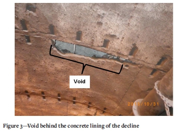
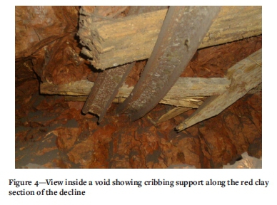
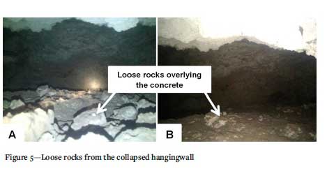
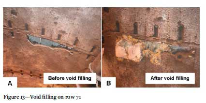
A borehole camera was used to inspect the condition of the voids behind the concrete lining, as well as to estimate their size. It was observed that the hangingwall of the voids showed a possible original hangingwall of the decline (Figure 3). The possible original hangingwall was supported by shotcrete and, in some areas, cribbing made up of gumwood planks and metal beams (Figure 4). The voids were not backfilled. In some areas the voids were filled with loose rocks that seemed to have been derived from the collapsed hangingwall (Figure 5).
The initial voids were formed when the gap between the original excavation and the concrete lining was not filled. This interpretation is supported by the fact that no voids were identified in areas where the concrete lining is not installed. The size of the voids increased due to self-mining and exposure of the rock to groundwater.
Inflow of water into the decline
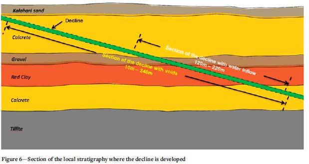
The stratigraphy which the decline is developed through is comprised predominantly of calcrete. The calcrete is underlain by gravel and red clay units (Figure 6). The red clay, unlike the calcrete and the gravel, is not permeable. As a result, laminar flows of groundwater occur in the gravel and calcrete units and the red clay unit is kept damp. Figure 6 shows groundwater ingress into the decline at sections where the decline intersects the aforementioned rock units.
The flow rate of the ingress water was measured in the gutter along the decline roadway. The flow rate was variable over time (0.9 - 8.7 L/minute) over time and could be correlated to seasonal changes . The volumes of the water ingress also dictated the start of the project.
Objectives and scope of the project
The purpose of the project was to carry out remedial work to prevent further damage to the concrete lining of the decline. The remedial work comprised filling of the voids behind the lining to prevent further self-mining of the hangingwall and sidewalls, and sealing to prevent groundwater ingress into the decline.
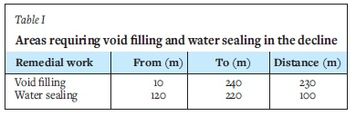
The scope of the remedial work was limited to the areas highlighted in Table I. Void filling was limited to filling cavities in the hangingwall and sidewalls of the decline, and water sealing was done around the decline, including the footwall.
Methodology
Voidfilling
Access to voids
The voids were accessed by drilling rows of holes along the hangingwall of the decline. The rows were spaced 3 m apart and a total of 77 rows were drilled. Each row comprised three holes as depicted in Figure 7. Hole 2 was drilled in the centre of the hangingwall and the side holes (holes 1 and 3) were drilled 0.5 m from the sidewall and 2.0 m from hole 2. The length of the holes was not fixed, but was determined by the intersection depth of a void or water loss during the drilling process.

Filling of voids
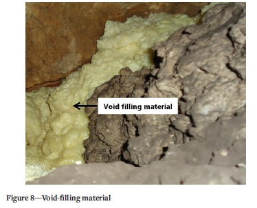
ISO (Industrial Synthetic Oils) developed a proprietary void-filling and a water-sealing product. The exact composition of the polymers cannot be disclosed due to confidentiality agreements. The void-filling material that was recommended is pumped as two polymer fluids that are mixed in the nozzle prior to injection. The mixture of the two components is exothermic and produces 'foam' that rapidly expands to fill the void and then harden (see Figure 8). The setting time is estimated to be one minute. Considering that the void-filling material would flow down-dip, the filling of voids commenced from the bottom of the decline and progressed up-dip. One row of holes was filled at a time, starting with the holes on the sidewalls and followed by the hole in the hangingwall.
The holes were filled in this order to build the void fill from the sidewalls up to the hangingwall. A hole was considered to be completely filled when void-filling material started seeping out of the hole being pumped or another hole in the same or an adjacent row.
Quality assessment of the void filling
The quality of the void filling was assessed by drilling check-holes on the hangingwall of the decline. The position of check-holes was determined based on the quantity of void-filling material pumped through hole 2. A check-hole was drilled if the void-filling material pumped was less than 32 kg or greater than 500 kg. Random check-holes were also drilled in areas where there was no visible evidence of the void-filling material penetrating cracks in the concrete lining. Each check-hole was surveyed with a borehole camera for cavities. If cavities were observed, these holes were re-filled.
Water sealing
Drilling of holes
A total of 40 rows of holes were drilled along the decline, each spaced 3 m apart. Thirty-five rows were drilled in the water area, and five rows down-dip of the water area to create a barrier that would prevent the water from progressing to the lower areas of the decline. Each row was drilled 1.5 m from a row of void-filling holes and comprised eight holes as depicted in Figure 9. The holes in one row were drilled and spaced as follows:
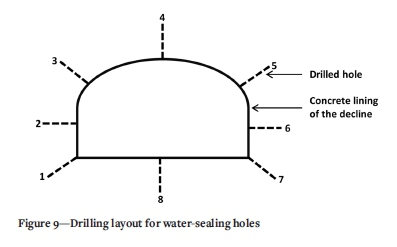
> Holes 1 and 7 on the sidewall 0.5 m from the footwall
> Holes 2 and 6 on the sidewall 1.8 m from the footwall
> Holes 3 and 5 on the hangingwall 0.5 m from the sidewall and 2 m from hole 4
> Holes 4 on the hangingwall 2.5 m from the sidewall
> Hole 8 on the footwall 2.5 m from the sidewall.
The length of the holes was limited to 3 m as it was planned to create a seal with an effective thickness of at least 2 m around the decline.
Grouting of holes
The recommended grouting material consists of a mix with two polymer fluids that are mixed in the injection nozzle while being injected. The fluids infiltrate cracks and joints before setting as an impermeable rubber coating. Cementing powder can be added to adjust the viscosity of the pumped fluid. The setting time for the water sealant is estimated to be about 20 minutes. In the presence of groundwater that may wash the fluids away, a catalyst is added to speed up the reaction. The setting time in this case varied between 10 seconds and one minute, depending on the quantity of catalyst added.
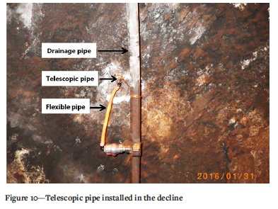
Water sealing commenced once void filling was completed. Water sealing was started by grouting the five rows of holes that were drilled down-dip of the water area. One row was sealed at a time; starting with the footwall holes (holes 1, 7, and 8) followed by the sidewall holes (holes 2 and 6) and then the hangingwall holes (holes 3, 4, and 5). A hole was considered to be completely grouted when the water-sealing fluids started seeping out of the hole being grouted or another hole that had not yet been grouted. Once the bottom barrier had been completed, water sealing was undertaken in the water area. It commenced at the top of the decline and progressed down-dip so as to direct the water down the decline to the bottom barrier. Two telescopic pipes were installed in the water area to allow water to drain off. The telescopic pipes are connected to flexible pipes which direct the water into a drainage pipe, as illustrated in Figure 10. The water is then fed along the water drainage channel to the bottom of the decline, from where it is further handled by the underground water management system.
Quality assessment of the water sealing
The quality of the water sealing was assessed by conducting visual inspections of the decline. If excessive groundwater ingress was observed, additional holes were drilled and grouted in the area concerned.
Results and discussion
The depth of the holes drilled to intersect the voids behind the concrete lining depends on the lithology intersected by the decline and the lining. It is suggested that the overbreak in the gravel units during excavation was greater than in the calcrete and red clay units. The concrete lining is 0.50 m thick and the average depth of holes drilled to access the voids was calculated to be 0.96 m. The minimum depth drilled was 0.56 m, and the maximum 1.30 m.
Figure 11 shows the consumption of void fill and water-sealing grout. The consumption of void fill was generally low around the portal and increased towards the groundwater ingress areas. This would suggest that the void fill material is affected by the presence of flowing groundwater. The challenge therefore was to apply correct batching of the void fill material. The mixture needed to remain fluid enough to migrate throughout the required volume of the void behind the lining, but to react and expand before being diluted too much by groundwater, which would reduce the efficiency of the reaction. From a comparison of the void fill and grout consumption per section, the correlation between high consumption of void fill material and water sealing grout consumption is evident. The main challenge in water sealing in unconsolidated material is that there is no specific point of water ingress that can be targeted for sealing, unlike for example a joint or fracture in a hard, impermeable rock. The groundwater has a tendency to migrate to the unsealed portion and create a new point of ingress, but to a very limited extent.
Void filling was completed successfully. Stability was achieved without affecting the integrity of the concrete lining. Evidence of the effectiveness of the void filling is visible in the decline. The void-filling material penetrated cracks in the concrete lining as illustrated in Figure 12.
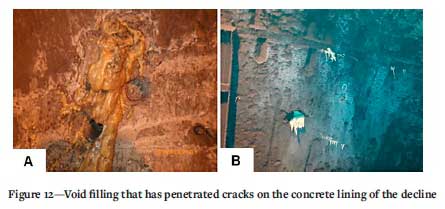
Figure 13 shows photographs of one of the voids before and after being filled.
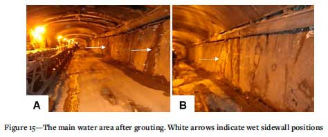
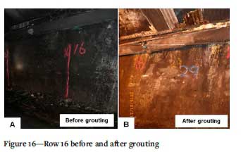
Water sealing was also completed successfully. The water volumes after the completion of the project were found to have decreased compared to the same period the prior year. Figures 14 and 15 show the ingress surface areas along the decline before and after completion of the project. The ingress of groundwater into the decline has been reduced to some residual dampness. Figure 16 shows photographs of a portion in the main water ingress area before and after water sealing and grouting.

Conclusions and recommendations
The remedial work was recommended following detailed investigations of the condition of the decline, which highlighted two main issues that were compromising the stability of the decline:
> Voids were identified behind the concrete lining of the decline. Self-mining was occurring on the hangingwall and sidewalls as the voids were not filled with any material to provide confinement
Water was flowing into the decline at areas where the decline intersected calcrete, gravel, and red clay units. The water was softening the concrete lining and deteriorating the rock mass.
The remedial work that was completed included void filling and water sealing. The void filling involved filling voids with void-filling foam to provide confinement and prevent further self-mining of the hangingwall and sidewalls. Water sealing was undertaken to create a seal around the decline in areas where groundwater inflows were observed. The water sealing was supported with a groundwater ingress management system.
A quality assessment of the remedial work indicated that the void filling and water sealing succeeded in meeting the aim of the project - to produce a near-dry decline with stabilized ground conditions behind the concrete lining.
Acknowledgements
We would like to thank Worley for permission to publish this paper, as well as Christo Kuhl, Henk Gouws, and Christopher Melamu, who gave permission on behalf of the client. We also acknowledge Gerrie Bezuidenhout and Raymond Mateveke for their contribution, and Donovan Munro for the review of the final draft. This paper is based on a presentation at given at the 3rd Young Professionals Conference, 9-10 March 2017 at the innovation hub in Pretoria.
References
Kuleshov, V.N. 2012. A superlarge deposit - Kalahari manganese ore field (Northern Cape, South Africa): Geochemistry of isotopes and genesis. Lithology and Mineral Resources, vol. 47. p. 217. [ Links ]
Steenkamf, N.C. 2014. Challenges of developing a ventilation shaft in Kalahari and Karoo Formations, Northern Cape, South Africa. Proceedings of the 12th AusIMM Underground Operators' Conference. Australasian Institute of Mining and Metallurgy, Melbourne. pp. 81-88. [ Links ]
Tsikos, H. 2000. Petrographic and geochemical constraints on the origin and post-depositional history of the Hotazel iron-manganese deposits, Kalahari Manganese Field, South Africa. PhD thesis, Rhodes University. Grahamstown, South Africa. 292 pp. [ Links ]
 Correspondence:
I. Serepa
Email: ikza87@gmail.com
Received: 27 Nov. 2018
Revised: 20 Nov. 2020
Accepted: 27 Jan. 2022
Published: March 2022

