


Services on Demand
Article
 English (pdf)
 Article in xml format
 Article references
Indicators

Related links
-
 Cited by Google
 -
 Similars in Google
Share

 Permalink
Journal of the Southern African Institute of Mining and Metallurgy
On-line version ISSN 2411-9717
Print version ISSN 2225-6253
J. S. Afr. Inst. Min. Metall. vol.121 n.10 Johannesburg Oct. 2021
http://dx.doi.org/10.17159/2411-9717/1597/2021
ARTICLES
Resistance spot welding of a thin 0.7 mm EN10130: DC04 material onto a thicker 2.4 mm 817M40 engineering steel
K.A. AnnanI; R.C. NkhomaII; S. NgomaneIII
IDepartment of Materials Science and Metallurgical Engineering, University of Pretoria, South Africa. https://orcid.org/0000-0002-9623-8106
IIEngineering Department, Faculty of MIT, Malawi University of Science and Technology, Malaw. https://orcid.org/0002-6407-432X
IIIGraduate school of Technology Management, University of Pretoria of Pretoria, South Africa
SYNOPSIS
The effects of welding current, electrode force, and welding time in a resistance spot weld were studied to investigate the effectiveness of welded joints between a thin EN10130: DC04 material and a thicker 817M40 part, through analysis of the microstructural and mechanical properties. All welded specimens were subjected to tensile testing at room temperature (25°C) and sub-zero temperature (-46°C) to test the strength of the welded joints. No full button failure was observed at either room temperature or sub-zero temperature after optimization of the weldng parameters. The fusion zone was observed to consist mainly of martensitic phase, due to rapid quenching, while the HAZ was composed of clusters of martensite in a ferrite and bainite matrix. The base 817M40 metal remained fully ferritic after welding. The hardness was found to increase with increasing welding current. An increase in nugget size, indicating good fusion of the weld, was observed with an increase in the welding current.
Keywords: microstructure, resistance spot weld, hardness.
Introduction
817M40 steel, also known as EN24T, is a Ni-Cr-Mo high hardenability, high tensile strength, and high wear resistance steel. EN24T can be heat treated to obtain a wide range of improved mechanical properties (Ramazani et al., 2015; Khan et al., 2008; Choi et al., 2011). This grade is very popular and widely used for many high-strength applications where a good combination of strength and impact properties is essential in large components (Ramazani et al., 2015; Khan et al., 2008). EN10130:DC04 is, however, a non-alloy steel suitable for applications requiring high ductility such as cold forming of components with complex profiles at high deformation speed (Khan et al., 2008).
Welding of 817M40 steel sheet in the hardened and tempered condition should be carried out with great caution, as the mechanical properties can be altered significantly through the welding process (Ramazani et al., 2015; Choi et al., 2011; Al-Mukhtar and Doos, 2013; Ghazanfari and Naderi, 2013). The most widely used method for joining two different materials such as EN24T and EN1030:DC04 is resistance spot welding (RSW), due to the fact that different configurations can be obtained with this method (Al-Mukhtar and Doos, 2013; Ghazanfari and Naderi, 2013; Wan, Wang, and Zhang, 2014; Pouranvari, 2011). Factors that influence the RSW process include the current passing through the workpiece, the time for which the current flows through the workpiece, the electrode pressure, and contact area between the electrode tip and the workpiece (Wan, Wang, and Zhang, 2014; Pouranvari, 2011; Singh et al., 2019). The most widely investigated RSW parameters that need to be controlled to achieve a good weld joint include the welding current, time, and electrode force (Ghazanfari and Naderi, 2013). The welding current has been found to be an influential parameter in determining the strength of the weld joint, since an increase in welding current leads to an increased heat flow, which influences the microstructural changes (Ghazanfari and Naderi, 2013; Raut and AchwaL, 2014).
The welding current provides the necessary heat for melting and therefore has a direct bearing on the microstructural changes (Khan et al., 2008; Wan, Wang, and Zhang, 2014; Pouranvari, 2011; Singh et al., 2019; Raut and AchwaL, 2014; Ali, Khan, and Moeed, 2015). It has been found that a higher welding current increases the strength of the weld nuggets due to the increased weld nugget area of the steel. The different weld regions whose microstructure impacts the mechanical properties of the welded joints include the base metal (BM), the heat-affected zone (HAZ), and the fusion zone (FZ) (Pouranvari, 2011). The microstructure of the FZ or nugget diameter, which is determined by the heat input, also affects the mechanical behaviour of the welded joint.
RSW is one of the electric welding methods that rely on heat, time, and pressure and is widely used in the automotive industry. Determining the settings for heat, time, and pressure is not an easy task, as highlighted by Nayaka et al. (2012 and Nasir and Khan (2016). It is more of an art than science, and is done through experimental test work. Set quality checks such as (shear) tensile tests, penetration, nugget visual inspection, and dimensional checks are used to determine 'pass' or 'fail' criteria (Singh et al, 2019; Liu et al, 2019; Pouranvari, 2017; Pouranvari, Sobhani, and Goodarzi, 2018).
The environment in which a material is applied also influences the properties of the material, including the strength as well as the microstructure (Ali, Khan, and Moeed, 2015, Pouranvari, 2017; Lee and Chang, 2020). It is, therefore, important to characterize the microstructure evolution during welding and its influence on the final mechanical properties of the steels. It has been reported that the failure mode depends primarily on the size of the fusion zone, and failure tends to occur under the pull-out mode as the fusion zone increases in size (Zhao, Zhang, and Lai, 2018; Sun, Stephens, and Khaleel, 2007). In the current study we investigated the effects of welding current, welding time, and electrode force on the tensile shear strength of resistance spot welded joints at different temperatures.
Materials and experimental procedure
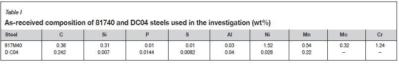
A 2.4 mm thick 817 M40 steel was used as a base metal and 0.7 mm EN10130: DC04 steel as thin material. The chemical compositions of the steels are presented in Table I. The surfaces of the metals were cleaned with 1.0 M HCl solution and a metal brush to remove any contamination before welding was done.
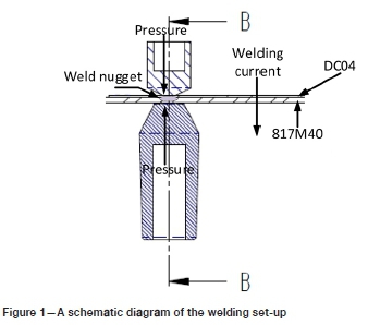
RSW was performed using a base metal of 2.4 mm thickness and a 0.7 mm thin material. The RSW tests were carried out using 45° truncated cone Cr-Zr- Cu containing electrodes with a 6 mm face diameter from Resistance Welding Manufacturers' Association (RWMA). The bottom electrode (tip) was shaped to follow the contour of the inside diameter of the cylinder for proper current flow and distribution. The parameters used were determined following a series of tests conducted to optimize the welding conditions. The values were selected so as to ensure a minimum nugget diameter of 4Vt, where t is the sheet thickness, after welding so that industrial welding conditions were maintained as far as possible (Sun, Stephens, and Khaleel, 2007). Four sets of RSW tests were done at one weld condition in order to evaluate the effect of the parameters on the weld.
Table II presents the parameters used in the welding process through a variation process to ensure a total of 24 tests in a round-robin situation. The holding rate (cooling rate) was kept at a maximum of approximately T°C/s. Each test was conducted three times to ensure repeatability.
Figure 1 presents a schematic diagram of the welding set-up used.
The samples for testing at sub-zero temperature were placed in dry ice in a vacuum container for 2 hours before being removed for tensile testing. The temperature of the samples was ascertained to be at least below -50°C at the time they were taken from the vacuum container so that the temperature at the testing time did not rise above -46°C. The tensile tests were carried out on an MTS Criterion 45 machine at room temperature (25°C) and sub-zero temperature (-46°C) at a crosshead velocity of 2 mm/min and the interfacial fractured surfaces of the samples examined under a metallurgical stereo microscope. Metallographic samples from the pulled weld nuggets were cut with a precision saw, mounted, and ground with a Struers Tetrapol-25 grinding machine using silicon carbide (SiC) paper sizes of 240, 400, 600, 800, and 1200 followed by polishing to a mirror-like finish using diamond suspension down to 1 urn for 3 minutes. All metallographic samples were prepared in accordance with ASTM 407 standard (ASTM, 2015). The mechanically prepared metallographic samples were etched in 2% Nital and examined under an Olympus BX51M microscope. The fractured surfaces were analysed using a JEOL SEM at working distance of 15 mm and 20 kV to establish the nature of the fracture following the tensile test. Hardness testing was carried out over the fusion zone, HAZ, and the BM using a Future Tech hardness machine. A diamond-type indenter was used for measurement, with a load of 2 kgf and dwelling time of 10 seconds. The hardness measurement was repeated with three patterns and the average value calculated.
Results and discussion
Examination of interfacial fractured surfaces
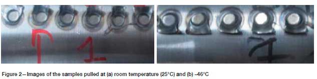
Figure 2 shows images of the samples pulled at different temperatures, illustrating the nature of fracture that occurred. As seen, no full button failure or full pullout was observed in any samples as only partial pullout was recorded. Samples tested at both room temperature and -46°C underwent partial interfacial fracture, as illustrated in Figure 2.
Figures 3 and 4 show the nugget morphology and the macroscopic morphology of the cross-section of the welded joints of samples welded using different conditions and pulled at room temperature and sub-zero temperature. The morphologies show cracks, but no shrinkage hole in the fusion zone for different welding currents used (Ramazani et al., 2015; Nayaka et al., 2012). All cross-section morphologies showed the welding characteristics zones of interest FZ, HAZ, and BM. It was also observed that the nugget diameter after pulling increased with increasing welding current in samples pulled at room temperature as well as those pulled at sub-zero temperature.
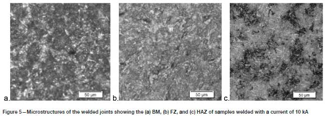
An increasing depth of penetration into the parent material was observed as the welding current increased from 6 kA to 12 kA, with values increasing from 1.2 mm to 2 mm, showing good fusion in all the welds. A good level of fusion and penetration was observed in the samples welded with a current of 10 kA. The samples pulled at both 25°C and -46°C all underwent ductile fracture, as shown in the SEM micrographs in Figure 5.
Microstructural observations
From the typical cross-section morphologies of the welded joints, three zones of interest namely the FZ, HAZ, and BM, were identified for microstructural examination. The microstructures of these zones are shown in Figure 5. The temperature of the BM remains below the transformation temperature of the steel and no transformation took place, as depicted by the microstructure in Figure 5a (Ramazani et al., 2015). The FZ experienced a high temperature during welding and a fast cooling rate thereafter, leading to phase transformation of austenite to martensite (Ramazani et al., 2015; Nayaka et al., 2012; Pouranvari, Sobhani, and Goodarzi, 2018). The martensite has a columnar texture with solidified needle-like structures as shown in Figure 5b. Figure 5c shows the microstructure of the HAZ following rapid post-weld cooling which resulted in the transformation of the austenitized structure to undissolved ferrite and bainite clusters (Lee and Chang, 2020; Zhao, Zhang, and Lai, 2018). The microstructure of the HAZ is made up of martensite clusters formed by decomposition of C-rich austenite regions in the ferrite matrix. The microstructure of the HAZ changed appreciably with increasing welding current, with a greater volume of martensite and bainite and less ferrite phase formed at higher currents.
The fractured surfaces of the pulled samples were examined using SEM in order to determine the nature of the fracture. The samples pulled at 25°C and -46°C both underwent ductile fracture, as shown in the SEM micrographs in Figure 6.
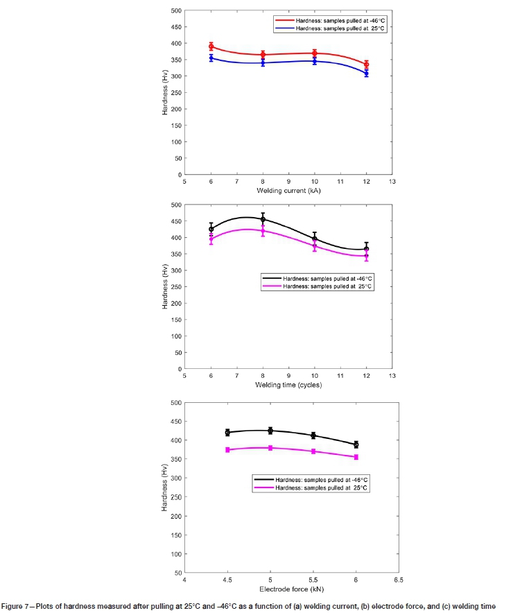
Hardness measurements
Figure 7 shows the measured hardness values as a function of the welding conditions for samples tensile-tested at room temperature and sub-zero (-46°C). The hardness of all the samples tested at sub-zero temperature is higher than for those tested at room temperature. This increase in hardness can be attributed to the fresh martensite that might have transformed in the sub-zero tensile test samples (Nayaka et al., 2012; Sherepenko et al, 2019; Rao et al., 2017). The effect of the electrode force on hardness (Figure 7b) is lower than that of welding current, (compare with Figure 7a). The increase in martensitic content following fast cooling after welding resulted in increased hardness, as shown in the hardness profiles in Figures 7a and 7c, which also show the effect of welding current and time on the hardness (Sherepenko and Jüttner, 2018; Sherepenko et al., 2019). In Figure 7a, the decrease in hardness with increasing welding current is observed in samples pulled at room temperature and at sub-zero temperature (Rao et al, 2017; Mohamadizadeh, Biro, and Worswick, 2020). A similar profile of softening is also observed with increasing welding time, as shown in Figure 7c.
Tensile properties
The influence of welding current, electrode force, and welding time on the nugget diameter, energy absorbed before fracture, as well as the maximum load experienced before fracture are presented in Figure 8 for samples pulled at room temperature and at sub-zero temperature (-46°C). The tests at different temperatures were carried out to evaluate the effect of the environment on the welded joint strength.
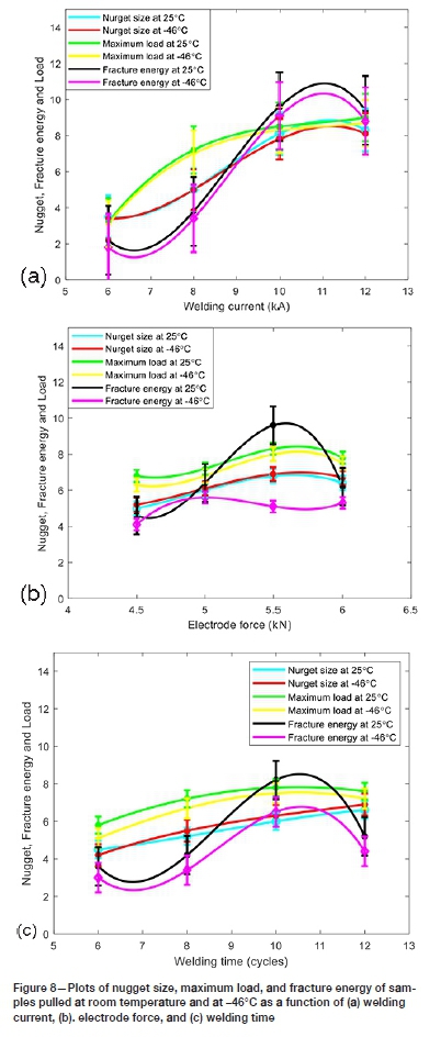
An increase in nugget size was recorded with increasing welding current. The maximum load to fracture and failure energy also varied with welding current. Figure 8b indicates that the maximum nugget size was obtained at an electrode force of 5.5 kN. At electrode forces lower than 5.5 kN, expulsions were recorded due to the decreased heat input, leading to a nugget size that did not provide effective contact. The results also shows that the nugget size and failure performance of the weld joint decrease with an increase in welding time beyond 10 cycles as a result of welding defects (Rao et al., 2017). The samples with increased nugget diameters also exhibited the highest pulling strength, as pullout fracture was observed in these samples. The decrease in maximum load and fracture energy for samples pulled at sub-zero temperature indicates increased brittleness in these samples (Ramazani et al., 2015; Nayaka et al., 2012; Rao et al., 2017). The brittleness is also confirmed by the increased hardness values for the samples pulled at sub-zero temperatures. This indicates that the temperature environment within which the welded component is used influences the mechanical properties, which is bound to affect the performance in such environments. A penetration depth of 81% was observed as the recorded penetration of 2.00 mm in the 2.44 mm parent material. A low penetration rate is associated with a small nugget size, while penetration of 75% and above is reported to indicate improved weld strength quality Ramazani et al., 2015; Choi et al., 2011). A combination of the parameters led to an increase in the nugget size, showing that each of the parameters has an influence, and only through a careful combination of the required parameters can optimal strength be obtained. In this work the optimum results were obtained at a welding current of 10 kA, electrode force of 5.5 kN, and welding time of 10 cycles.
Conclusions
The effects of welding current, welding time, and electrode force on the quality of weld joints between a 2.4 mm EN24T steel and a 0.75 mm EN10130: DC04 steel were investigated. The following conclusions are drawn.
> Increased welding current led to an increase in hardness, and a reduction in the fracture energy and maximum load in samples tensile tested at both room temperature and sub-zero temperatures.
> Increases in welding current, welding time, and electrode force resulted in an increased nugget size. The increase in nugget size led to an increase in the penetration and strength of the joint.
> The welding current is the most significant welding parameter influencing the quality of the weld joint and the type of microstructures obtained
> No full button failure was observed in either the samples pulled at room temperature or those pulled at -46°C after optimization of the welding conditions.
> The optimal welding conditons were a welding current of 10 KA, electrode force of 5.5 kN, and welding time of 10 cycles.
References
Ali, 1., Khan, M.I., and Moeed, K.M. 2015. Comparative study of spot welding process parameters on microstructure and mechanical properties of ASS 304 and ASS 202 steel. International Journal of Mechanical and Industrial Technology, vol. 3, no. 1. p: 35-39. [ Links ]
Al-Mukhtar, A.M. and Doos, Q. 2013. The spot weldability of carbon steel sheet. Advances in Materials and Engineering, vol. 2013. Article no. 146896. https://doi.org/10.1155/2013/146896 [ Links ]
ASTM E 407-07. 2015. Standard practice for etching metals and alloys. ASTM International, West Conshohocken, PA. [ Links ]
Choi, H., Park, G., Lim, W., and Kim, B. 2011. Evaluation of weldability for resistance spot welded single-lap joint between GA780DP and hot-stamped 22MnB5 steel sheets. Journal of Mechanical Science and Technology. vol. 25. Article no. 1543. [ Links ]
Ghazanfari, H. and Naderi, M. 2013. Influence of welding parameters on microstructural and mechanical performance of resistance spot welded high strength steels. Acta Metallurgica Sinica (English Letters), vol. 26, no. 5. pp. 635-640. [ Links ]
Khan, M.I., Kuntz, M.L., Biro, E., and Zhou, Y. 2008, Microstructure and mechanical properties of resistance spot welded advanced high strength steels. Materials Transactions, vol. 49, no.7. pp. 1629-1637. [ Links ]
Lee, T.H. and Chang, Y.C. 2020. Effect of double pulse resistance spot welding process on 15B22 hot stamped boron steel. Journal of Metals, vol. 10. pp. 1-17. [ Links ]
Liu, X. D., Xu, Y.B., Misra, R.D.K., Peng, F., Wang, Y., and Du, Y.B. 2019. Mechanical properties in double pulse resistance spot welding of Q&P 980 steel. Journal of Materials Processing Technology, vol. 263. pp. 186-197. [ Links ]
Mohamadizadeh, A., Biro, E., and Worswick, M. 2020. Shear band formation at the fusion boundary and failure behaviour of resistance spot welds in ultra-high-strength hot-stamped steel. Science and Technology of Welding and Joining, vol. 25. pp. 1-8. [ Links ]
Nasir, Z. and Khan, M.I. 2016. Resistance spot welding and optimization techniques used to optimize its process parameters. International Research Journal of Engineering and Technology, vol. 3, no. 5. pp. 887-893. [ Links ]
Nayaka, S.S., Hernandez, V.H.B., Okitaa, Y., and Zhoua, Y. 2012. Microstructure-hardness relationship in the fusion zone of TRIP steel welds. Materials Science and Engineering A, vol. 551. pp 73-81. [ Links ]
Pouranvari, M. 2011. Effect of resistance spot welding parameters on the HAZ softening of DP980 ferrite-martensite dual phase steel welds. World Applied Science Journal, vol. 15, no. 10. pp. 1454-1458. [ Links ]
Pouranvari, M. 2017. Critical assessment: dissimilar resistance spot welding of aluminium/steel: challenges and opportunities. Journal of Materials Science and Technology, vol. 33. pp. 1705-1712. [ Links ]
Pouranvari, M., Sobhani, S., and Goodarzi, F. 2018. Resistance spot welding of MS1200 martensitic advanced high strength steel: Microstructure-properties relationship. Journal of Manufacturing Processes, vol. 31. pp. 867-874. [ Links ]
Ramazani, A., Mukherjee, K., Abdurkhmanov, A., Abbasi, M., and Prahl, U. 2015 Characterization of microstructure and mechanical properties of resistance spot welded DP600 Steel. Metals, vol. 5. pp. 1704-1716. doi:10.3390/met5031704 [ Links ]
Rao, S.S., Chhibber, R., Arora, K.S., and Shome, M. 2017. Resistance spot welding of galvannealed high strength interstitial free steel. Journal of Materials Processing Technology, vol. 246. pp. 252-261. [ Links ]
Raut, M. and AchwaL, V. 2014. Optimization of spot welding process parameters for maximum tensile strength. International Journal of Mechanical Engineering and Robotics Research, vol. 3, no. 4. pp. 506-517. [ Links ]
Sherepenko, O. and Jüttner, S. 2018. Transient softening at the fusion boundary in resistance spot welded ultra-high strengths steel 22MnB5 and its impact on fracture processes. Welding World, vol. 63. pp. 151-159. [ Links ]
Sherepenko, O., Kazemi, O., Rosemann, P., Wilke, M., Halle, T., and Jüttner, S. 2019 Transient softening at the fusion boundary of resistance spot welds: A phase field simulation and experimental investigations for Al-Si-coated 22MnB5. Metals, vol. 10. pp. 10. [ Links ]
Singh, D.K., Sharma, V., Basu, R., and Eskandari, M. 2019. Understanding the effect of weld parameters on the microstructures and mechanical properties in dissimilar steel welds. Proedia Manufacturing, vol. 35. pp. 986-991. [ Links ]
Sun, X., Stephens, E.V., and Khaleel, M.A. 2007. Effects of fusion zone size and failure mode on peak load and energy absorption of advanced high-strength steel spot welds. Welding Research, vol. 86. pp. 18-25. [ Links ]
Wan, X., Wang, Y., and Zhang, P. 2014. Effects of welding schedules on resistance spot welding of DP600 steel. ISIJ International, vol. 54, no. 10. pp. 2375-2379. [ Links ]
Zhao, Y., Zhang, Y., and Lai, X. 2018. Analysis of fracture modes of resistance spot welded hot-stamped boron steel. Metals, vol. 8. pp. 764. [ Links ]
 Correspondence:
K.A. Annan
Email: kofi.annan@up.ac.za
Received: 13 Apr. 2021
Revised: 12 Sep. 2021
Accepted: 22 Sep. 2021
Published: October 2021
This paper was first presented at the Mine-Impacted Water from Waste to Resource Online Conference, 10 and 12, 17 and 19, 3 and 24 November 2020

