


Services on Demand
Article
 English (pdf)
 Article in xml format
 Article references
Indicators

Related links
-
 Cited by Google
 -
 Similars in Google
Share

 Permalink
Journal of the Southern African Institute of Mining and Metallurgy
On-line version ISSN 2411-9717
Print version ISSN 2225-6253
J. S. Afr. Inst. Min. Metall. vol.121 n.10 Johannesburg Oct. 2021
http://dx.doi.org/10.17159/2411-9717/1109/2021
ARTICLES
The effect of decarburization on the fatigue life of overhead line hardware
J. CalitzI; S. KokII; D. DelportIII
ITshwane University of Technology, South Africa and Eskom - Research, Testing and Development, South Africa. https://orcid.org/0000-0002-2719-9406
IIUniversity of Pretoria, South Africa. https://orcid.org/0000-0001-9453-2806
IIITshwane University of Technology, South Africa. https://orcid.org/0000-0003-1963-556X
SYNOPSIS
Altering the microstructure in order to improve the tensile properties of bow shackles resulted in inconsistency in the fatigue performance. This raises the question whether the inconsistency in fatigue life can be attributed to microstructural changes along the profile of the shackle or to decarburization at the surface.
Bow shackles forged from 080M40 (EN8) material were subjected to different heat treatments in order to alter the microstructure. The shackles were subjected to five different fatigue load cases, which represented typical loads experienced at termination points for an overhead power line with a span length of 400 m, with changes in conductor type, configuration, wind, and ice loading.
Although the change in microstructure does improve both the tensile and fatigue performance, we found that the depth of the decarburization layer has a greater effect on the high cycle fatigue life of bow shackles than the non-homogeneous microstructure.
Keywords: bow shackle, decarburization, fatigue, hardness, microstructure.
Introduction
In order to reduce the cost of an overhead power line, larger overhead conductor diameters and longer line span lengths (distance between two structures) are used, hence reducing the number of structures used for a specific line length (Calitz et al., 2005).
The prime function of overhead line hardware is to connect the phase conductor to the insulators and the insulators to the structure (tower) (Eskom, 2014). The design philosophy of reducing the number of structures results in an increase in the mechanical loading on termination points at structures, especially at termination (strain) structures, as a result of the increase in conductor mass (Calitz et al., 2005). Consequently, the line hardware strength classes have to increase.
Quenching and tempering heat treatment methods are typically used to increase the mechanical strength of line hardware, which often result in a nonhomogeneous microstructure along the profile, particularly of forged components with a complex geometry, due to the difference in cooling rates for the different cross-sectional areas (Wieser, 1980).
Therefore, when bow shackle failures occurred as a result of fatigue damage on certain span lengths (sections) on the 765 kV electrical network in particular, it raised the question what impact poor control during the heat treatment of bow shackles has on their fatigue performance.
This study investigates the influence of microstructure and decarburization on the fatigue behaviour of forged line hardware, specifically bow shackles.
Literature survey
Gildersleeve (1991) investigated the relationship between decarburization and fatigue strength of a manganese-molybdenum through-hardening steel (605M36). Rotating bending tests were used to determine the fatigue behaviour. The specimens had decarburized layers up to 1 mm in depth. The results showed that the fatigue limit was mostly independent of the depth of decarburization. Gildersleeve also examined surface carbon concentration and found the fatigue limit to be linearly dependent upon the carbon concentration at the surface.
Adamaszek and Broz (2001) investigated the effects of decarburization on hardness changes in carbon steels caused by high-temperature surface oxidation. They found that the decarburization resulted from annealing, and caused the grains near the surface to grow. The authors explain that during the decarburization process oxygen penetrates the surface scale through cavities, pores, and cracks. This oxygen reacts with the different elements in the metal, causing decarburization. The extent of decarburization is greater for metals with a higher Fe content. The authors also found hardness changes due to the decarburized layers, resulting in lower fatigue resistance.
Hankins and Becker (1932) tested forged specimens of four types of steel of different hardnesses which included both low- and medium-carbon steels, under cantilever-type rotating bending. The hourglass-shaped specimens consisted of both as-forged surface finish specimens, from which the flash had been trimmed before testing, and machined and polished specimens.
A metallurgical analysis of the test specimens showed that the hardness of the decarburized surface was lower than that of the interior material. The specimens with the largest difference between surface and interior hardness displayed the largest difference in endurance limit between the polished and as-forged surface conditions.
The authors state that decarburization is the main cause of reduced fatigue life for specimens in the as-forged surface condition.
Experimental methods
Manufacturing of test samples
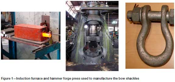
Bow shackles were hammer-forged from 35 mm diameter 080M40 (EN8) material, using a closed die system making use of a Banning pneumatic hammer forged press as depicted in Figure 1. The 300 mm long billets were induction heated between 1100°C and 1250°C and the forging temperature was between 950°C and 1250°C. The holes in the eye section were punched immediately after the component was forged.
After heat treatment the shackles were galvanized using a centrifuge galvanizing method. The bath had a zinc content of 99.7% and the temperature of the molten zinc was maintained at 450°C. The shackles were removed before solidification of the zinc could occur on the component surfaces and placed in a centrifuge, then spun for several seconds to remove excess zinc from the surface. Thereafter, the components were transferred to a quench tank where they were cooled to allow handling.
Heat treatment of test samples
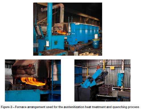
The normalizing heat treatment was conducted in a protective (controlled) atmosphere using propane gas to prevent scaling of the component surface. The shackles were placed in baskets and loaded into the preheated furnace at 820°C. Subsequently, the temperature was increased to 920°C within 75 minutes. The temperature was maintained for 2½ hours, after which the components were removed and air cooled to room temperature while still in the baskets. Figure 2 depicts the heat treatment equipment used.
In order to alter the microstructure the shackles were subjected to two different hardening and tempering heat treatments, namely 'AR' (as received) and 'HTM' (heat treatment modification).
> Austenitization heat treatment: Following the normalizing heat treatment, the steps were:
• AR: Reheated to 880°C for approximately 40 minutes, followed by quenching in oil which was maintained at a temperature range between 60°C and 80°C.
• HTM: Reheated to 880°C for approximately 1 hour, followed by quenching in running water.
> Tempering heat treatment: The last stage of the heat treatment process was tempering, which was conducted at:
• AR: 515°C for 4 hours followed by oil quenching
• HTM: 520°C for 4 hours followed by quenching in water.
Testing
The high cycle fatigue testing was conducted on a MTS Landmark servohydraulic test machine. As testing was not conducted on standard fatigue specimens, but on components (the bow shackles), the test requirements of ASTM E466-96 (ASTM, 2002) were used as a guideline to develop a force-controlled constant amplitude axial fatigue test procedure in MTS TestSuite Multipurpose Elite (mpe) software, which was used for setting the test parameters and recording the test data.
As depicted in Figure 3, a back-to-back shackle arrangement was used to simulate installation practices. The tongue fittings measuring 20 mm in thickness and a bolt hole of 20 mm was used to connect the back-to-back shackle arrangement to the MTS test machine grips.
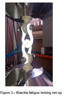
The bolts used were not the standard 8.8 grade bolts that are supplied with the 210 kN shackles, but were machined from martensitic stainless steel, which provided improved mechanical properties compared to the 8.8 grade material, in order to minimize the deformation associated when subjecting the bolt to bending loads when the shackle is loaded in tension.
The selection of which hardware strength class to use for a hardware assembly is determined by the ultimate tensile strength of the conductor attached to it; thus hardware rated at 210 kN can accommodate different conductor types and configurations. Therefore the mechanical loading introduced to the hardware assembly is directly linked to the tension within the conductor, which is affected by several factors such as conductor type, temperature, span length, wind, and ice loading.
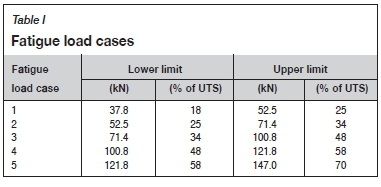
In-house developed software titled Tower Loader SANS v2.3d, based on SANS 10280 (SANS, 2013), was utilized to calculate the different loading conditions for a 210 kN rated hardware assembly. The loading conditions were subdivided into fatigue load cases which are summarized in Table I. The amplitude (lower and upper limits) is expressed in load (kN) based on the percentage of the ultimate tensile strength of the shackles, which was taken as 210 kN.
After each fatigue test, the test specimen was sectioned approximately 20 mm from the fracture end in order to measure the hardness of the material. In all cases, the leg section failed. In addition, specimens were removed from the eye and crown sections. The specimens were cut using a Labotom-15 manual cut-off machine with cutting/cooling fluid. Both transverse and longitudinal specimens were removed.
The metallographic preparation included the hot mounting of specimens in an ATM Opal 460 hot mounting press at 180°C and 250 bar pressure using thermosetting bakelite resin in order to improve the handling of the specimens.
To remove the surface damage caused by cutting, the mounted specimens were ground with rotating discs of silicon carbide paper. The grinding procedure involved several stages, using a finer grit paper with each subsequent stage in order to remove the scratches from the previous coarser paper. The last stage was conducted with a 1200 urn grit paper, followed by two stages of polishing with diamond suspension of 3 and 1 μm grit to produce a smooth surface finish.
After cleaning with running water and acetone, the specimens were etched with 5% Nital, a solution of nitric acid and methanol, in order to reveal the microstructure of the steel. The specimens were immediately washed with methanol and dried after etching.
A computer-controlled inverted metallurgical Zeiss Axio microscope with ZEN 2 core imaging software was used to conduct the metallographic examinations and to capture digital images of the microstructure, at different magnifications.
Vickers hardness measurements were taken across the prepared surfaces of both transverse and longitudinal specimens, utilizing a semi-automated Emcotest DuraScan 70 hardness machine with Ecos work flow software. Measurements were taken at 1 mm intervals by applying a load of 10 kgf.
Results
Figure 4 depicts the number of cycles to failure versus the mean applied load for the 'as received' shackles.
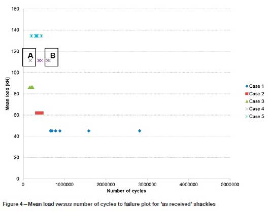
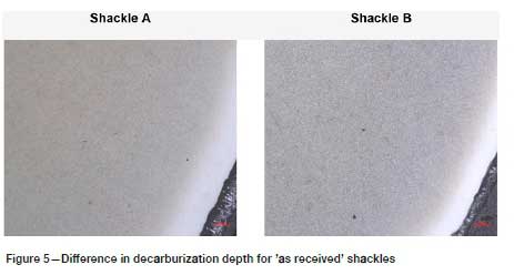
Figure 5 depicts the microstructures of the metallographic specimens removed from the leg section of shackle specimens A and B in the vicinity where the fatigue fracture occurred. The specimen with the higher ferrite content, namely shackle B, underwent a higher number of cycles to failure. As depicted in Figure 5, shackle B also had a decarburization depth 38% less than that of shackle A.
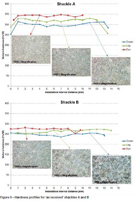
As depicted in Figure 6, shackle B had an overall lower hardness than shackle A. However, shackle B revealed better fatigue performance than shackle A, as depicted in Figure 4. This can be attributed to shackle A having a larger decarburization depth and greater hardness difference between the surface and the parent (inner) material.
The altered microstructure of the HTM shackles that was obtained by the modified heat treatment resulted in an improvement in the fatigue performance of the bow shackles for loading cases 1 and 2, as illustrated in Figure 7. No improvement in fatigue performance was gained at higher loadings. A previous study (Calitz, Kok, and Delport, 2019) concluded that the curved shape of the leg contributes towards premature fatigue failure at higher loads The leg section is not only subjected to tensile stress when the shackle is under tension, but also to a large degree of bending stress as a consequence of its shape. The increase in bending stress with an increase in loading results in localized overstressing of the material, promoting fatigue crack initiation and propagation.
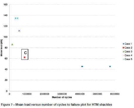
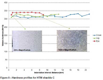
Figure 8 depicts the hardness profiles and micrographs taken at the leg section of shackle C. Shackle C represents the overall condition of the HTM shackles. The decarburization depth was less prominent for the HTM shackles and the hardness difference between surface and parent material was minimal compared to shackle A (Figure 6).
Conclusion
The fatigue performance of a bow shackle can be improved by altering its microstructure. However, this improvement by metallurgical means is limited to lower load cases, as the curved shape of the leg contributes towards premature fatigue failure. The leg section is not only subjected to tensile stress when the shackle is under tension, but also to a large degree of bending stress as a consequence of its shape. The increase in bending stress with an increase in loading results in localized overstressing of the material, promoting fatigue crack initiation and propagation.
In addition, the fatigue performance of the shackles at lower stress levels was significantly influenced by the depth and hardness of the decarburization layer. A decrease in hardness and an increase in the depth of the decarburization layer resulted in poor fatigue performance, even with an increase in the through thickness hardness of the leg section.
This difference in hardness is one explanation for the decreased life in the high cycle fatigue (HCF) region for forged shackles, since higher hardness (higher strength) is a desired property for long fatigue life.
The fatigue behaviour of the forged bow shackles concurs with the findings of Hankins and Becker (1932), that decarburization associated with the as-forged surface condition is the main cause of reduced fatigue life and not the non-homogenous microstructure.
Acknowledgements
The lead author would like to acknowledge Eskom Holdings SOC Limited for their commitment to providing him with the opportunity to further his engineering skills and knowledge. Through Eskom's vision in the Eskom Power Plant Engineering Institute (EPPEI) programme he is able to pursue his doctoral degree in engineering.
References
ADAMAszEK, K. and Broz, P. 2001. Decarburization and hardness changes in carbon steels caused by high temperature surface oxidation in ambient air. Diffusion and Defect Data: Defect and Diffusion Forum, vol. 194. pp. 1701-1706. [ Links ]
ASTM. 2002. E 466-96. Standard practice for conducting force controlled constant amplitude axial fatigue tests of metallic materials. ASTM International, West Conshohocken, PA. [ Links ]
Calitz, J., Haridass, B., Jacobs, B., Retef, J., and Plessis, P.D. 2005. Line hardware. The Planning, Design and Construction of Overhead Power Lines. Bisnath, S., Britten, A. C., Cretchley, D. H., Muftic, D., Pillay, T., and Vajeth, R. (eds). Crown Publications, Johannesburg. pp. 441-482 [ Links ]
Calitz, J., Kok, s., and Delport, D. 2019. The effect of geometry on the fatigue life of overhead line hardware. Journal of Failure Analysis and Prevention, vol. 19, no. 5. pp. 1401-1406. [ Links ]
Eskom. 2014. Specification for suspension and strain assemblies and for hardware for transmission lines. Sandton, South Africa. [ Links ]
Gildersleeve, M. 1991. Relationship between decarburization and fatigue strength of through hardened and carburizing steels. Material Science and Technology, vol. 7. pp. 307-310. [ Links ]
Hankins, G. and Becker, M. 1932. The fatigue resistance of unmachined forged steels. Journal of the Iron and Steel Institute, vol. 126. pp. 205-236. [ Links ]
SANS. 2013. SANS 10280-1. Overhead power lines for conditions prevailing in South Africa. Part 1: Safety. SABS Standards Division, Pretoria: pp. 30, 33. [ Links ]
Wieser, P.F. 1980. Supplement 11: Hardenabilty and heat treatment. Steel castings Handbook (5th edn). Steel Founders' Society of America. [ Links ]
 Correspondence:
J. Calitz
Email: calitzj@eskom.co.za
Received: 4 Feb. 2020
Revised: 25 Feb. 2021
Accepted: 13 Sep. 2021
Published: October 2021
This paper was first presented at the Mine-Impacted Water from Waste to Resource Online Conference, 10 and 12, 17 and 19, 3 and 24 November 2020

