


Services on Demand
Article
 English (pdf)
 Article in xml format
 Article references
Indicators

Related links
-
 Cited by Google
 -
 Similars in Google
Share

 Permalink
Journal of the Southern African Institute of Mining and Metallurgy
On-line version ISSN 2411-9717
Print version ISSN 2225-6253
J. S. Afr. Inst. Min. Metall. vol.121 n.9 Johannesburg Sep. 2021
http://dx.doi.org/10.17159/2411-9717/1254/2021
PAPERS OF GENERAL INTEREST
Analysis of rope load sharing on multi-rope friction winders
M.E. GreenwayI, II; S.R. GroblerII; S. BilessurisII
IUniversity of Western Australia, Australia
IIWorley Services Pty Ltd, Perth, Australia
SYNOPSIS
Ensuring that all the head ropes on a multi-rope friction winder share the load equally has been a design and maintenance issue since they were first developed. Accurate machining of the rope grooves is necessary to meet this objective. Early analysis of the change of rope loads for ropes in grooves that are mismatched in depth treated the grooves as rigid. Groove depth tolerances deduced from this analysis are stringent and difficult to achieve in practice. Test work indicated that the inherent flexibility of groove lining materials alleviates the load-sharing problem. However, no analysis of rope load changes due to mismatched flexible grooves has been published. In this paper we develop new equations for the rope load variation for flexible grooves. By allowing flexibility to reduce to zero, the corresponding rigid rope groove equations are obtained. New criteria for tolerable groove depth variations are developed from this analysis, which depend on the flexibility of the groove lining material.
Keywords: friction winder, rope load sharing, mismatched rope grooves, flexible groove liners.
Introduction
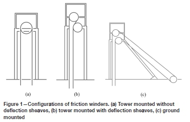
Friction winders are often called Koepe winders after Frederick Koepe, their inventor, who first developed a single-rope friction hoist in Germany in 1878. The first multi-rope friction winders were developed and commissioned in Germany in 1947 by GHH. Ever since, these winders have proved popular and cost-effective winding installations in the mining industry world-wide. Friction winders can be positioned directly in the headframe - when they are referred to as 'tower mounted' - or adjacent to the headframe - when they are referred to as 'ground mounted'. Tower-mounted winders sometimes have deflecting sheaves to reduce the spacing between the ascending and descending ropes to suit the conveyance locations in the shaft. These configurations are illustrated in Figure 1.
The issue of load sharing between the head ropes has been a legitimate concern since the first developments and is both a design and a maintenance issue for all friction winders to the current day. Useful technical papers (Hitchin, 1958; Eithun, Landau, and Mondal, I960; Bar, 1976; Dean, 1970) published in the literature in the period 1950 - 1976 have since formed the basis of rope load control, monitoring, and maintenance on friction winders. The realization that perfect load sharing was unachievable resulted in the industry norm for the control of head rope loads, aiming at controlling these loads to within ±10% of the mean rope load.
Assuming rigid grooves, Hitchin (1958) discussed the effect of grooves of unequal depth on the rope load changes for a two-rope winder, illustrating the changes graphically. No equations from his analysis were provided. He drew attention to tower-mounted winders being more sensitive to groove mismatch than ground-mounted winders. Eithun, Landau, and Mondel (1960) also considered rigid grooves, providing equations of the right functional form although containing mathematical discrepancies. They used an example of a four-rope friction winder. Bar (1976), quoting Mettler (1956), gave an equation for the maximum rope load caused by mismatched groove depths for an «-rope winder. No analysis behind this equation was given. All these authors, besides stressing the need for matching rope groove circumferences to maintain tolerable rope load sharing, mention that left unchecked, gross rope slip will occur in the groove of smallest circumference, leading to accelerated groove wear. Dean (1970) linked the structural failure of friction winder ropes to poor control of groove depths and gross rope slip.
The papers by Bar (1976) and Hitchin (1958) both mention the alleviation of rope load deviations from the mean when flexible groove liner material is used. Neither gives an analysis of the form of load variation during the wind. Bar refers to experiments conducted and quotes peak rope load reductions to 50% for rubber and 33% for plastic materials when the flexibility of the groove lining material is considered.
In this paper we develop new equations for the rope load variation for flexible grooves. By allowing flexibility to reduce to zero, the corresponding rigid rope groove equations are obtained. New criteria for tolerable groove depth variations are developed from this analysis, which depend on the flexibility of the groove lining material.
The load-sharing problem is quite a subtle one, so the paper takes a measured, gradual approach, leaving the mathematical developments, which may be distracting to some readers, to the Appendix. Firstly, the importance of achieving good load sharing is outlined, and all the causes of unequal load sharing are mentioned together with strategies and operating practices to alleviate them. The most troublesome cause - that of groove depth discrepancies - is taken forward and becomes the focus of the paper.
Prior to introducing the new parameter of the problem - that of the groove's flexibility - a qualitative explanation is given of how the rigid grooves on a two-rope Koepe winder with different depths generate unequal loads in the head ropes when the winder operates, in both the conveyance ascending and descending modes. The load changes are illustrated by replicating a graph of Hitchin (1958).
Friction winders with four and six ropes are much more common than two-rope winders. It is necessary to generalize the two-rope analysis to an n-rope winder. This is done in the Appendix by first assessing the situation where only one groove (taken as groove 1) is disturbed so as to be shallower than the remaining grooves, which all share the same depth. Then by using a superposition principle, this restriction is relaxed so that each groove can have a unique depth. The resulting equations can be used to predict the loads in the individual ropes of an n-rope friction winder with given defined groove depth differences. The rigid groove equations are quoted in the text and illustrated by replicating a graph of Eithun, Landau, and Mondal (1960) for the case of a four-rope winder.
The same equations are rearranged to provide the criteria for groove accuracy that will maintain the variation of rope loads within tolerance (±10% of mean rope load). This equation is applied to an example winder to illustrate how stringent the accuracy criteria become.
Finally, a new parameter to represent the groove flexibility is introduced and numerical values for the example winder are developed from a 2D finite element analysis of the groove material. The rope load variations that apply to a Koepe winder with flexible grooves for ascending and descending conveyance travel are given in the text. This is illustrated by repeating the Hitchin example, but this time with a flexible groove material to illustrate the benefit. A new rope groove depth accuracy criterion is developed to account for the groove flexibility, together with a graph to illustrate the improvement offered by groove flexibility.
The importance of load sharing among the head ropes of a multi-rope friction winder
Equal sharing of the suspended load among the ropes on a multi-rope friction winder is desirable for several reasons.
> Regulators allow the statutory rope factors of safety to be calculated based on equal load sharing. Any discrepancy in load sharing means that some ropes will take higher loads than the mean rope load and others will take lower loads. Effectively, the ropes with the higher load may be breaching the factor of safety regulation.
> Head rope fatigue damage is a function of the axial load range experienced in the ropes during winding, and to a lesser extent due to the ropes bending around the drum and sheaves. Both these aspects are exacerbated in ropes that take higher loads than the mean rope load. This results in shorter rope life.
> If the loads in the ropes vary severely it is possible for the ropes to slip in the grooves in the winder drum, which leads to accelerated wear of the rope groove friction lining material and may result in structural upset of the rope.
> If the loads in the ropes with the lower loads reduce to the extent that they become slack, there is the possibility that the ropes will distort or kink and become permanently damaged, requiring their immediate discard (reduced life).
Factors that influence unequal load sharing among the head ropes
Differences in the head rope loads of multi-rope friction winders arise fundamentally from:
1. Differences in free lengths of the head ropes at the attachment to the conveyances
2. Differences in the rope-length advance rate of the ropes as they pass over the driving friction drum. This is affected
by:
a. Variations in the rope tread circumferences of the driving friction drum
b. Differences in the strain of the individual ropes (due to load differences)
c. Differences in the diameters of the various ropes
d. Differential deflection of the rope grooves of the winder drum under the different imposed rope loading
3. Differences in the modulus of elasticity of the ropes
4. Differences in the amount of 'permanent stretch' of the ropes.
The best practice strategy to mitigate the issues arising from differences in the rope properties (points 2c, 3, and 4 above), is to purchase and install ropes from the same production run. Furthermore, when one rope requires discarding, all the head ropes are discarded and replaced simultaneously. This is common practice.
The appropriate strategy to mitigate factor 2d above is to ensure the drum radial stiffness is the same for each rope groove.
Head rope attachments are normally adjustable so that rope lengths can be equalized/adjusted on initial installation (to mitigate factor 1), and in service (to mitigate factor 4).
Other than equalizing the free lengths of the head ropes, the most significant influence mentioned above is the differences in rope groove circumference (factor 2a above) (or equivalently the effective groove depth). This is the focus of this paper.
Qualitative discussion of load variation in a two-rope friction winder with mismatched groove depths
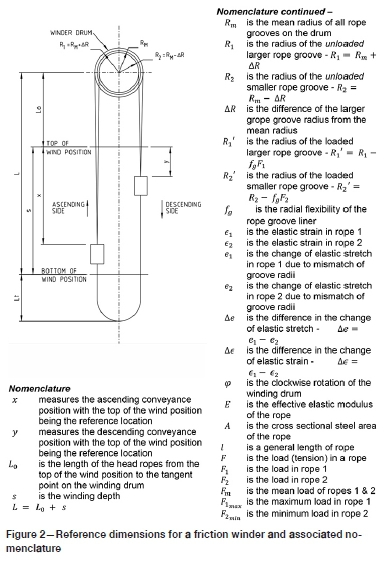
Consider a friction drum that is assumed 'rigid' (i.e. it doesn't deflect under the rope loads) and the friction tread material is similarly rigid (doesn't compress under the rope loads). The drum has two grooves of mean groove radius Rmbut with a difference from the mean of ∆R - one groove radius being Rm+ ∆R (groove 1) and the other being Rm- AR (groove 2). Refer to Figure 2 and the associated nomenclature.
Initially, consider the conveyance positioned at shaft bottom where the two ropes of equal length and with identical physical properties are anchored to the conveyance. The rope loads at the conveyance will be equal. At the top end of the ropes where they begin to wrap around the friction drum, the rope loads will be higher than at the capels as the weight of the rope itself also needs to be supported. Nevertheless, since the ropes have identical properties (including mass per metre) the loads there will be equal. The elastic stretch in each rope will therefore be the same. The total length of rope suspended from the drum to the conveyance is therefore made up of the unstretched or free length plus the elastic stretch. Under constant speed conditions, the loads in the ropes at the drum remain the same for the ideal configuration because friction winders employ 'balance ropes' that compensate for the weight of the hoist ropes that pass over the drum. In this paper, the effects of additional load changes due to normal accelerating and decelerating loads are neglected.
Now consider the lengths of rope 1 and rope 2 as the winder hoists the conveyance up from shaft bottom. For the first turn of the friction drum, groove 1 will pass a greater length of rope to the descending side of the drum than groove 2. On the ascending side of the drum, this will cause the elastic stretch in rope 1 to increase and that in rope 2 to decrease, with the result that the strain (elastic stretch per unit length) in rope 1 will increase and that in rope 2 decrease. For the next turn of the drum, the difference in the rope lengths passed over the drum will be the same but because these ropes now have a different amount of strain, the difference in the effective 'unstrained' lengths of rope passed across the drum reduces from the previous drum turn. And so on for subsequent turns. This poses the question whether groove 2 may eventually pass more unstrained length of rope than groove 1 per turn of the drum. The analysis in the Appendix shows that after reaching about the 1/3rd shaft depth position this difference in unstrained lengths passed becomes negative - in other words the shallower groove passes more 'unstrained' length of rope than the deeper groove, with the result that the difference in stretch now progressively reduces for every further turn of the drum. However, the difference in stretch does not reduce to zero.
The difference in load (tension) between the ropes is proportional to the elastic strain, which is the difference in elastic stretch per unit length of the rope - the rope length varying throughout the wind. The stretch difference increases from zero at the start of the ascending wind, increasing the strain and the load in rope 1 and reducing it in rope 2. These changes in strain are small initially due to the long length of rope, but they become more rapid towards the end of wind when the remaining length of rope approaches its minimum length. Despite the stretch reducing towards the top of the wind, the analysis shows the strain keeps increasing due to the shortening length of the ropes. When the winder reaches the top of wind position the discrepancy in rope load will be greatest. The load in rope 1 will have increased above the mean load to reach a maximum value at the end of wind, and the load in rope 2 will have reduced below the mean to reach a minimum.
Considering the ropes on the descending conveyance, the initial rope loads in ropes 1 and 2 will be the terminating values for the ascending conveyance (assuming that there is no load added or removed from the conveyances and that no slip of the ropes over the drum has occurred). The rope coming across the drum from the ascending side initially has a zero stretch difference, but more rope will be fed into rope 1 than rope 2 due to the difference in groove radii. The difference in strained lengths of rope passed over the drum from the ascending side is zero initially, but progressively reflects the strain differences in the ascending ropes. Compared to the initially short ropes, the effective length of the descending ropes increases rapidly as the conveyance descends. This has the effect of quickly reducing the differences in strain (and hence load) as the ropes grow in length. Again, in the latter part of the wind, the shorter rope groove (groove 2) passes more unstrained rope than groove 1, which has the effect of reducing the difference in rope stretch and hence in rope load. At the end of the wind the ropes have equal load.
The pattern of rope load versus conveyance location in the shaft is thus quite different between the ascending side and the descending side. Using Equation [A5] from the Appendix, this is illustrated in Figure 3, which agrees with the analysis of Hitchin (1958).
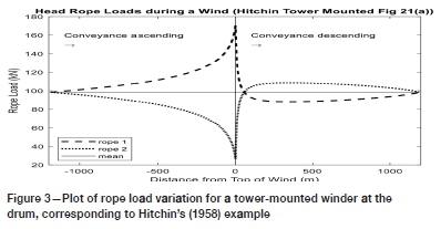
In the plot, the load in one of the ropes reduces to almost zero (see Figure 3). The analysis of rope loads is valid only if all loads remain positive (i.e. in tension). It is possible, by increasing the groove depth discrepancies, for the rope loads to decrease to zero. This emphasises the need to manage rope loads in practice. Another issue is that the T1/T2tension ratio across the drum may change sufficiently to result in gross rope slip on the drum. While the analysis can be used to predict incipient slip, if slip occurs the analysis will be invalid.
Equations for rope load variation of an n-rope friction winder with mismatched groove depths
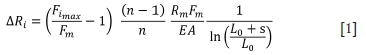
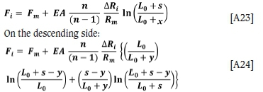
The loads in the individual ropes of an n-rope friction winder with given defined groove depth differences are developed in the Appendix. For rigid grooves, these equations are: Ascending side:
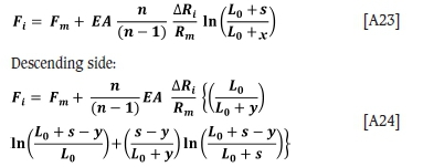
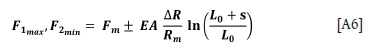
In these equations, the notation is as given in Figure 2, but in addition, Fiis the load in the 'ith' rope, which has a groove depth disparity of ∆Ri. The maximum and minimum loads in the respective ascending ropes are given by
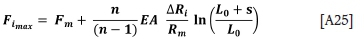
with the maxima resulting from positive ∆Riand minima from the negative ∆Ri- To keep the maximum rope load due to a rope groove radius discrepancy of AR,- as low as possible, L0, Rm, and n should be made as large as possible where the design allows.
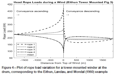
Equation [A25] agrees with the equation quoted in Bar (1976) except that the  term is inverted in Bar. Equations [A23] and [A24] are used with the parameters from the four-rope example discussed by Eithun, Landau, and Mondal (1960) to prepare a plot of the rope load variation at the drum (see Figure 4) - the groove depths for ropes 3 and 4 were equal in this example. The plot given in Eithun, Landau, and Mondal is replicated.
Groove depth tolerance criteria
Equation [A25] allows a determination of the maximum allowable rope groove discrepancy. It can be rearranged as follows:
To restrict the maximum rope load variation to ±10% of the mean rope load, this criterion becomes:
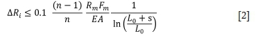
For illustrative purposes, this equation is applied to an example four-rope tower-mounted cage and counterweight friction winder with the following parameters:
> Cage empty mass M0= 13 000 kg
> Cage payload Mp= 10 000 kg
> Winding distance s = 420 m
> L0= 12 m
> Mean rope groove radius Rm= 1.3 m
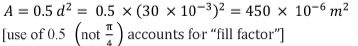
> Head rope diameter d = 30 mm
> Mass per unit length of the head rope ph= 4.0 kg/m
> Rope modulus of elasticity E = 110 GPa
> Rope steel area
For the fully loaded cage, Equation [2] yields ∆Ri< 0.040 mm. It is immediately apparent that this is a very small deviation and it is almost impractical to machine to this tolerance. If this example winder were ground-mounted with say L0= 92 m, then Equation [2] would give ∆Ri< 0.084 mm.
Analysis of flexible groove linings and mismatched groove depths
The influence of the flexibility of the groove lining material is analysed in the Appendix. To achieve this, a new parameter needs to be introduced. This is the extent to which the groove radius is reduced with an increase in the tension in the rope wrapping around that groove liner. If the change of rope tension, AT, causes an additional elastic reduction of the groove radius by Ar, then the radial flexibility of the groove lining material, denoted fg, is given by fg= ∆r / ∆T.
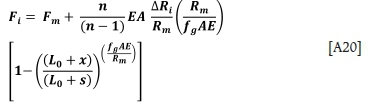
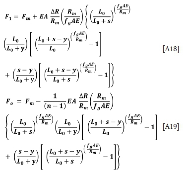
The resulting form of the rope load variations during a wind, developed in the Appendix for an n-rope friction winder with flexible groove liners, are given by:
On the ascending side:
On the descending side:
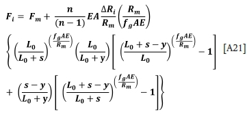
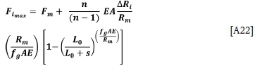
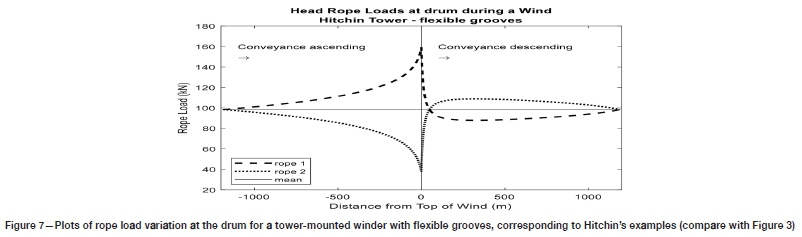
The maximum and minimum loads in the individual ropes are given by
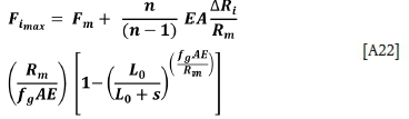
with the maxima resulting from positive ARiand minima from the negative ARi.
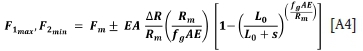
Examining the form of Equation [A22], the term inside the large brackets is a ratio of length parameters similar to the rigid groove case, but for the flexible groove a power term is evident  . This can be interpreted as the ratio of the flexibility of the liner material to the flexibility of a piece of hoist rope equal in length to the groove radius.
Assessment of groove liner flexibility
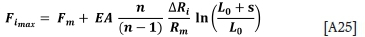
To assess numerically the benefit of flexible groove liners requires a typical value of fgto be determined. Reverting to the example winder mentioned above, it has a groove liner shown in Figure 5. The figure depicts an elevation of the drum showing the four grooves. A detailed cross-section through one of the grooves on the drum is shown to illustrate how the material is retained in the groove. An isometric view of a segment of liner material is shown, as well as a dimensioned cross-section. The lining is a commercially available material (Becorit K25). This has a modulus of elasticity of 165 MPa and a Poisson's ratio of 0.4.
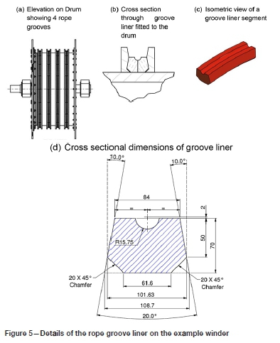
The rope exerts a pressure on the semicircular boundary of the rope groove. For the equilibrium of the rope wrapping around the drum under tension T , the equivalent line load per unit length of liner, P, exerted by the rope on the groove liner is P = 2 T/D where D is the drum diameter (i.e. the PCD of the rope on the drum). The pressure distribution on the rope groove in the liner is assumed to be a radial pressure varying sinusoidally such that the pressure is maximum at the bottom of the groove.
With the angle e measured from a horizontal axis at the centre of the rope, the pressure is given by p(e) = p0sin e, where p0is the maximum pressure attained. Horizontal and vertical components of this pressure distribution may be integrated to calculate the net horizontal and vertical forces. The net horizontal force is zero as expected. The net vertical force per unit length of liner is  where d is the groove diameter. For equilibrium, this must equal the applied line load. Hence p0, is related to the rope tension by p0 =
  . The specific pressure value used in the analysis is p0 = 2.43 MPa corresponding to a 60 kN/m line load and a head rope tension of 73.4 kN (due to the fully loaded cage).
To determine the deflection of the centre of the rope groove under the rope loading, a 2D finite element analysis has been undertaken using Nastran. The elements are plane strain and the material is hyper-elastic using a Mooney-Rivlin material model. The hyper-elastic modelling solution technique was used as the low modulus value of the groove lining material may lead to large strains. The boundaries of the liner in contact with the steel supports of the drum are treated as fixed except for the bevelled bottom corners, where there is a clearance to the supporting steel. These boundaries are free to deflect.
The deflections for the Becorit liner are shown in an exaggerated plot in Figure 6a. The deflection of the lowest point in the centre of the groove is 0.216 mm. This gives a groove flexibility under rope load of fg =  = 0.00294 mm per kN of rope load.
For a liner modelled in rubber with a modulus of elasticity of 12 MPa and a Poisson's ratio of 0.5, the corresponding deflections are shown in Figure 6b. The deflection of the groove centre is now 0.402 mm. In this case fg =  = 0.00548 mm per kN of rope load.
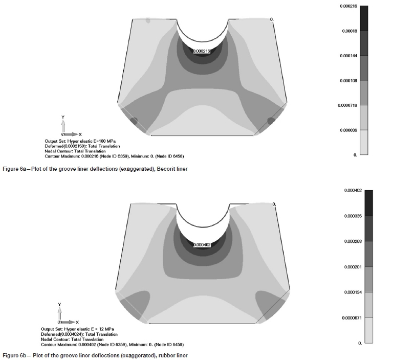
Discussion of rope load variation with flexible groove liners and revised groove depth tolerance
Using the value of fgdetermined here with the parameters of Hitchin's tower-mounted winder case allows that to be reassessed with flexible grooves. A plot of the rope load variations with flexible grooves in Becorit material is shown in Figure 7. This plot should be compared with Figure 3 for the rigid groove case. The maximum rope load reduces to 161.6 kN (5% lower) with the flexible grooves. With the liner in rubber, the rope load reduces by 8.8%.
From Equation [A22] the criterion on the allowable rope groove depths for flexible grooves to maintain the rope loads within ±10% of the mean rope load is
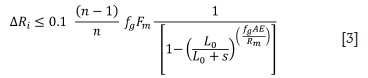
Using the parameters applicable to the example friction winder gives ∆Ri < 0.052 mm, which is 23% larger than the value considering the grooves as rigid. This gives some improvement in the tolerable groove discrepancy, making accurate machining easier.
The general improvement in groove depth tolerance with flexible rope groove liners can be demonstrated by ratioing the criteria of Equations [3] and [2]. A graph of  versus the
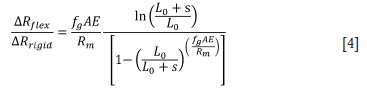
parameter  is shown in Figure 8 for various values of

Conclusion
Fundamental relationships for the variation of rope load in the head ropes of multi-rope friction winders have been determined. Both rigid grooves and grooves with flexible liners were considered. From these relationships, criteria that define the allowable tolerance on groove depth mismatch have been developed to maintain the rope load variations within 10% of the mean rope load. Through these criteria the extent to which existing flexible groove materials enhance the load sharing between the ropes has been demonstrated.
The design parameters that affect the severity of load variation with mismatched grooves have been discussed. In summary:
> Existing flexible lining materials can reduce rope load variations for a given groove depth mismatch by about 5%
> Winders with more head ropes provide better load sharing than those with fewer head ropes
> Ground-mounted winders have smaller rope load variations than tower-mounted winders for the same groove depth mismatch.
The basic relationships developed enable questions about the performance of rope load sharing in multi-rope friction winders to be answered. They may be used in various ways:
- To improve winding system performance to enhance rope
life
- To improve the design of rope groove flexible liners
- To forensically assess liner wear, and rope and conveyance behaviour problems that may develop if maintenance practice lapses
Acknowledgment
The authors wish to thank Worley and the University of Western Australia for permission to publish this paper.
References
Bar, s. 1976. Control of rope forces in multi-rope winding installations. The South African Mechanical Engineer, February. pp 1-12. [ Links ]
Dean, H. 1970. Hoist-rope stress analysis and preventative maintenance for multi-rope friction hoists. CM Transactions, vol. LXXIII. pp. 277-289. [ Links ]
Eithun, E., Landau, F., and Mondal, J. 1960. Load equalisation on multi-rope winders, The South African Mechanical Engineer, vol. 10. pp 111-138. [ Links ]
Hitchen, H. 1958. British Wire Ropes Publication 188: Multi-rope friction winders, Paper read to the Sheffield University Mining Society, 25 February. pp 1-35. [ Links ]
Mettler, E. 1956. Uber den Seilkraftausgleich bei Vierseil-forderrungen. Ausschnitt aus Entwicklungsarbeiten der Gutehoffnungshutte Sterkrade AG, Werk Sterkrade. R. Bergbau, H. 21. [ Links ]
 Correspondence:
M.E. Greenway
Email: malcolm.greenway@worley.com
Received: 15 Jun. 2020
Revised: 1 Aug. 2021
Accepted: 27 Aug. 2021
Published: September 2021
Appendix
Analysis of head rope load variations due to rope groove mismatch - flexible rope grooves
The analysis is first applied to a two-rope friction winder with one high and one low rope groove. It is then generalized to an n-rope friction winder with one high groove and all the others equal. It is further generalized by allowing every groove a unique groove depth. The nomenclature used has been given in Figure 2. The development of the groove flexibility parameter fgis discussed in the main text.
Development of rope load variation for a two-rope friction winder with flexible rope groove liners
Ascending conveyance
Consider the winder drum in the general position with the left-hand conveyance being hoisted up x distant from the top of the wind. Consider the difference in the lengths of ropes 1 and 2 passed over the drum during an increment of drum rotation by dφ.
Difference in the unstrained lengths = Difference in the increment of the loaded drum groove circumference minus the difference in the strained lengths
But the strained lengths of ropes 1 and 2 after the increment remain equal (both rope ends being attached at one end to the conveyance and at the other end to the drum). The difference in lengths 'reports' as a difference in the rope stretch between the two head ropes.
Therefore, the following equation can be written:
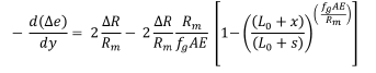
Now note that dφ = -  as x reduces as cp increases, hence the negative sign.
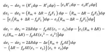
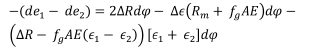
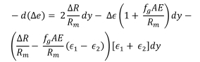
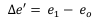
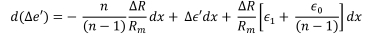
Neglecting products of small quantities such as  etc. and noting that ∆ e=
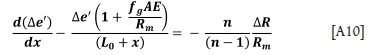
  , the above equation becomes
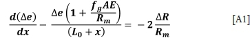
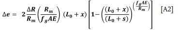
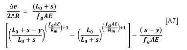
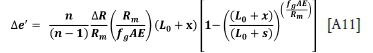
Solve this first-order ordinary differential equation by the 'Integrating Factor' method, noting that at the starting point of the upward wind, the difference in rope stretch (and hence the rope loads) is zero. i.e. when x = s, ∆e = 0. Hence
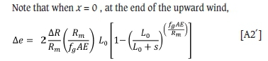
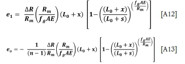
Now as this is a two-rope friction winder, ∆e = e1 - e2, and because the combined rope load always equals the weight of the ropes and conveyance attached, el + e2 = 0. Hence, e1 =  and e2 =
  . Rope stretch e and rope load F are related by the rope stiffness, which is given by
  where E is the modulus of rope elasticity, A is the cross-sectional steel area of the rope, and I is its length F=
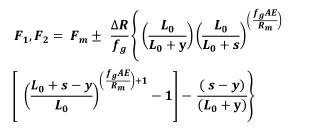
  e. Hence the loads in rope 1 and rope 2 can be written (with tne plus sign for F1 and the negative sign for
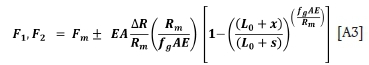
The maximum force in rope 1 and the minimum force in rope 2 are given by
with the selection of the appropriate sign.
The relationship for rigid grooves is obtained from Equation [A3] by allowing the flexibility to tend to zero and using the limit
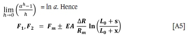
with
Descending conveyance
Now consider the descending side for the conveyance on the right-hand side in Figure 2. The starting loads in the head ropes 1 and 2 will be the ending loads of the previous upward wind and will be given by the relationships in Equation [A6] for F1and the corresponding equation for F2. Also, if y is measured down the ropes from the same reference position, y and φ will increase together. The ropes that are fed from the ascending conveyance into the initially short lengths of rope on the descending conveyance will start with same difference in their elastic stretch as at the termination of the ascending wind. This will change progressively, as has been calculated for the upcoming conveyance. The basic equation for the difference in the lengths of ropes 1 and 2 passed over the drum during an increment of drum rotation by j remains the same.
Difference in the unstrained lengths = Difference in the increment of the loaded drum groove circumference minus the difference in the strained lengths
except recognizing now that an increase in length passed through by rope 1 has the effect of reducing the existing difference in elastic stretch, and hence the sign on the left-hand side of the equation above is negative. Also, dφ =  , so using ∆e=
  and the solution for ∆e(x), which has been determined in Equation [A2], the incremental change in the difference of rope elastic stretch becomes
Neglecting products of small quantities such as  x e1, etc. and noting that ∆e =
  the above equation becomes
x and y are related through s = x + y. After substituting for x, the above equation may be integrated (using the condition for ∆e when y = 0 given by Equation [A2']:
This gives ∆e = 0 when y = s, which is the expected equality of rope loads at the bottom end of the wind.
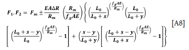
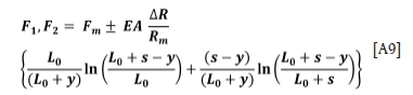
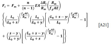
Proceeding as before, the rope load in rope 1 and rope 2 can now be written as
This equation can be rearranged as follows:
The maximum and minimum rope loads are as in Equation [A4].
As before, allowing the flexibility parameter to tend to zero produces the relationship for rigid grooves.
Generalization of rope load variation for an n-rope friction winder with flexible rope groove liners
Now consider a multi-rope friction winder with n ropes. Initially it is assumed that rope 1 groove is larger than all the others, which have the same radius. The following nomenclature is added to the previous list.
Nomenclature
n the number of head ropes used on the friction winder
R0the radius of all the grooves which are not disturbed
e0is the change of elastic stretch in a rope (o) in an undisturbed rope groove
e0 is the elastic strain in a rope (o) running in an undisturbed rope groove
∆e" is the difference in the change of elastic stretch. Ae" = e1- e0
∆e" is the difference in the change of elastic strain. ∆e" = e1 - e0
F0is the load in any rope running in an undisturbed groove Fmis the mean load of all the ropes F0minis the minimum load in the ropes running in an undisturbed groove
The radius of rope groove 1 exceeds the mean radius by an amount ∆R so that R1= Rm+ ∆R
The other groove radii have a radius R0, which is given by R0 = 
Consideration will be given now to the difference in rope stretch that develops between rope 1 and any one of the other ropes.
Ascending conveyance - one oversize groove
Consider again the incremental movement of the winder drum and the ascending conveyance.
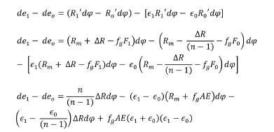
Now note that dφ = -  ; as x reduces as φ increases, hence the negative sign. Neglecting products of small quantities such as
  etc., the difference in stretch can be written
and noting that ∆e =  the above equation becomes
and this first-order equation can be solved as before, yielding
To obtain the relationship for rope stretch and rope loads, the requirement (from equilibrium of forces) is that ei + (n - 1)e0 = 0, hence e0 = -  and so ∆e'= e1,-e0, =
  e1= -(n -1)e0- e0 = -n eo . Hence
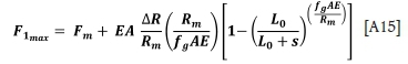
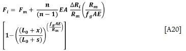
Proceeding as before from these differences in rope stretch, the load in rope 1 can be written
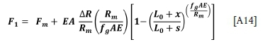
and the maximum force in rope 1 is given by
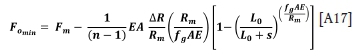
Similarly, the load in all the other ropes (rope o) can be written
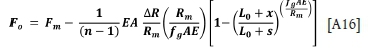
and the minimum load in the other ropes can be written
Descending conveyance - one oversize groove
For the descending side, the analysis proceeds in a similar manner to that done previously, yielding
The maximum and minimum rope loads occur on the ascending side and are given by Equations [A15] and [A17].
Application to n-rope friction winder with discrepancies on all grooves
The above relationships for an n-rope friction winder can be used to plot the rope load variations for both the ascending side and the descending side. They apply to a drum which has all grooves equal except for groove 1, which is over-size.
Initially, the above equations do not appear to be helpful to the general situation where each groove may have its own unique size. However, it can be recognized that the rope load variations are self-similar and scale linearly with the value of ∆R. Hence, contrary to first impressions, it is indeed possible to use the above relationships to determine the rope load variation for the rope in each groove of an n-rope friction winder. For the general situation, the groove depth variations from the mean radius Rm will be denoted ∆R1, ∆R2, .... ∆Ri, .... ,∆Rn. The actual groove radius of groove i is written
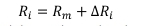
and the condition that the mean radius is Rmrequires

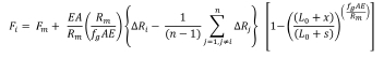
As the sum of the deviations from the mean is zero, some of the ∆Riwill be positive, and others will be negative. To obtain the unique loads in each rope which arise from the deviation of every groove from the mean, the loads from the equations above for each deviation acting alone are added up. The load arising in rope i from the deviation of groove rope i is offset by the loads arising in rope i from the other grooves, j, for j = 1, n with j ‡ i as follows:
For the ascending side:
and for the descending side:
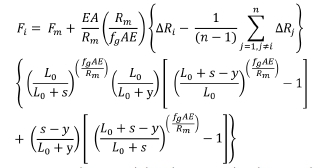
Now it can be noticed that the term in brackets involving the groove errors can be expressed alternatively as
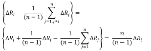
This allows some simplification of the loads as follows: Ascending side:
Descending side:
The maximum and minimum loads in the respective ropes are given by
with the maxima resulting from positive ARiand minima from the negative ∆Ri.
As before, allowing the flexibility parameter to tend to zero produces the relationship for rigid grooves. On the ascending side:
On the descending side:
The maximum and minimum loads in the respective ropes are given by
with the maxima resulting from positive ARiand minima from the negative ∆Ri.

