


Services on Demand
Article
 English (pdf)
 Article in xml format
 Article references
Indicators

Related links
-
 Cited by Google
 -
 Similars in Google
Share

 Permalink
Journal of the Southern African Institute of Mining and Metallurgy
On-line version ISSN 2411-9717
Print version ISSN 2225-6253
J. S. Afr. Inst. Min. Metall. vol.121 n.8 Johannesburg Aug. 2021
http://dx.doi.org/10.17159/2411-9717/690/2021
PROFESSIONAL TECHNICAL AND SCIENTIFIC PAPERS
A semi-empirical solution for estimating the elastic stresses around inclined mine stopes for the Mathews-Potvin stability analysis
P. Pagé; P. Yang; L. Li; R. Simon
Research Institute on Mines and Environment, Department of Civil, Geological and Mining Engineering, École. Polytechnique de Montréal, Canada. L. Li: https://orcid.org/0000-0002-3900-5234
SYNOPSIS
The Mathews-Potvin stability method is widely used in the Canadian mining industry as a starting point to determine the maximum dimensions of mine stopes. However, it cannot be applied to inclined (more frequently encountered) mine stopes without conducting numerical modelling to obtain the stress factor A, defined as a function of the ratio of unconfined compressive strength of intact rock to the induced principal stress on the exposed stope walls. The need to conduct numerical modelling significantly limits the application of the Mathews-Potvin method. In addition, given its empirical nature and main application for preliminary design, it is deemed undesirable to conduct numerical modelling, especially elaborate modelling. Alternatively, theoretical methods can provide a much simpler and quicker way to estimate stresses around stopes and the corresponding stress factors. Over the years, a large number of studies have been conducted to estimate stresses around openings excavated with various cross-sections. However, theoretical or graphical solutions remain unavailable for mine stopes that typically consist of horizontal floor and roof, and two parallel inclined walls (hangingwall and footwall). To remedy this situation, a series of numerical simulations is first performed for openings with vertical and inclined walls, including typical stopes commonly encountered in underground mines. A group of empirical solutions is then formulated to estimate the induced principal stresses at the roof centre and mid-height of the stope walls. The validity and predictability of the proposed solution have been verified using additional numerical simulations. The proposed solution can thus be used to calculate stresses and the resultant stress factors A around typical mine stopes with any inclination angle and height to width ratio, under any in-situ stress state, without conducting numerical modelling.
Keywords: Mathews-Potvin, inclined stope, simulation, semi-empirical solution.
Introduction
Ground stability is a challenging issue frequently faced by rock engineers. The trend towards larger and more powerful equipment to improve productivity requires larger underground openings. However, the dimensions of stable underground excavations are finite, limited by field stresses and rock mass conditions. The correct design of underground openings is thus of paramount importance.
The Mathews-Potvin method is a simple and useful tool for mining engineers. It is commonly used as a starting point to determine the dimensions of stopes or design the required support (e.g., Mathews et al. 1981; Potvin 1988; Hutchinson and Diederichs 1996; Li and Ouellet 2009). The Mathews-Potvin method is also used to estimate the unplanned dilution due to the slough that can take place around the hangingwall and footwall during blasting or muck-out of blasted ore (Scoble and Moss 1994; Clark and Pakalnis 1997; Kaiser et al. 1997; Diederichs and Kaiser 1999, Diederichs, Kaiser, and Eberhardt, 2004; Papaioanou and Suorineni 2016). Another application of the Mathews-Potvin method is to estimate the minimum span exposures to ensure the cavability (self-collapse) of ore in caving mining methods (Sunwoo, Jung, and Karanam, 2006).
Over the years, the Mathews-Potvin method has received extensive modifications (e.g., Mathews et al., 1981; Potvin, Hudyma, and Miller, 1989; Potvin and Milne 1992; Nickson 1992; Hadjigeorgiou, Leclair, and Potvin, 1995; Stewart and Forsyth 1995; Milne, Pakalnis, and Felderer, 1996; Clark and Pakalnis 1997; Germain and Hadjigeorgiou 1998; Suorineni 1998; Diederichs and Kaiser 1999; Trueman, Mikula, and Mawdesley, 2000; Mawdesley, Trueman, and Whiten, 2001; Suorineni, 1998; Suorineni, Tannant, and Kaiser, 1999a, 1999b; Stewart and Trueman, 2001; Suorineni, Henning, and Kaiser, 2001, Suorineni, Tannant, and Kaiser, 2001; Suorineni et al., 2001; Trueman and Mawdesley, 2003; Wang, 2004; Bewick and Kaiser, 2009; Capes, 2009; Li and Ouellet, 2009; Zhang, Hughes, and Mitri, 2011; Suorineni, 2012; Papaioanou and Suorineni, 2016; Madenova and Suorineni, 2020). An extensive review of various versions of this method was reported by Suorineni (2010).
For mine stope design, a major limitation associated with the Mathews-Potvin method is the need to conduct numerical simulations to obtain a key parameter, called the stress factor (A), which depends on the ratio of the unconfined compressive strength of intact rock to the induced principal stress (σ1) on the walls of the opening. When the geometry of the openings is simple, such as a circular cross-section, analytical solutions exist for estimating the stress around such openings (Kirsch, 1898; Hiramatsu, 1962; Logie and van, Tonder 1967; Hiramatsu and Oka, 1968; Li, 1997). More sophisticated analytical solutions are equally available for estimating the elastic stresses around tunnels with a vertical axis of symmetry, including openings with elliptical, rectangular, and arched walls (Logie and van Tonder 1967; Hoek and Brown 1980; Gerçek 1997; Exadaktylos and Stavropoulou 2002; Brady and Brown 2013).
For vertical mine stopes, graphical solutions used to estimate the induced stresses have been elaborated in two dimensions (2D plane strain; Potvin 1988; Stewart and Forsythe 1995) and three dimensions (Mawdesley, Trueman, and Whiten, 2001; Vallejos, Delonca, and Perez, 2017). In practice, however, orebodies are always inclined to a greater or lesser degree. Few theoretical or graphical solutions are available to assess the induced stresses around inclined stopes with one horizontal floor, one horizontal roof, and two parallel and inclined walls (hangingwall and footwall). Numerical modelling has to be performed to obtain the induced stresses for each specific mining project (Li and Ouellet, 2009). This requires not only the availability of pertinent software and hardware, but also qualified numerical modellers who have a good understanding of field conditions and the behaviour of the rock mass, and know in particular how to obtain reliable numerical outcomes. It is thus desirable to have theoretical solutions that can be used to estimate the stresses around inclined stopes.
In this paper, the Mathews-Potvin method is first briefly recalled for the sake of completeness. Numerical simulation results are then presented by considering inclined mine stopes surrounded by a homogenous, isotropic and linearly elastic rock mass. A large range of wall inclination angles, height to width ratios, and in-situ stresses are considered. Semi-empirical solutions are proposed to estimate the induced principal stresses on stope walls by applying the principle of superposition of linearly elasticity theory through a curve-fitting technique applied to the numerical results. The prediction capability of the proposed semi-empirical solutions is verified with additional numerical simulations. A typical example is also given to illustrate the application of the proposed solution.
The Mathews-Potvin method
The Mathews-Potvin method is an empirical method based on numerous field observations. This method relates the stability of an exposed wall to two factors - the hydraulic radius (HR) and the stability number (N). The former is defined as (Potvin 1988):

The stability number (N) of the exposed wall is defined by the following equation:

where Q is a modified rock tunnelling quality index, A is the rock stress factor, B is the joint orientation adjustment factor, and C is the gravity adjustment factor.
The parameter Q' resulted from a modification on the Rock Tunnelling Index (Q) of Barton, Lien, and Lunde (1974), is defined as follows:

where RQD is the rock quality designation, Jnis the joint set number, Jris the joint roughness number, and Jais the joint alteration number.
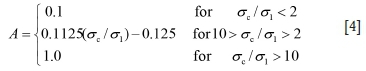
The rock stress factor A is a function of the ratio between the unconfined compressive strength of the intact rock (σc) and the induced major principal stress (σ1) on the exposed walls of a stope. The stress factor A can be expressed as follows (Potvin, 1988), which is further illustrated in Figure 1a:
Factor B considers the influence of joints on the stability of the studied exposed wall (Potvin 1988). It represents the effect of the angle between the most critical joints and the wall, as shown in Figure 1b. The gravity factor C depends on the individual influence of the inclination of the exposed wall and the inclination of the critical joints, as illustrated in Figure 1c. Once the stability number N and hydraulic radius HR are determined, the stability of the exposed wall can be evaluated using the chart of Mathews-Potvin, as shown in Figure 1d.
From Equation [4], one notes that the rock stress factor A proposed by Potvin (1988) has some limitations when the rock is submitted to a tensional stress. In this case, the induced principal stress σ1 is zero (for a 2D model) or non-zero in the third dimension (for a 3D model). Factor A can thus reach its maximum value of 1.0 independent of the tensile stress and tensile strength of the rock, which is unrealistic. Therefore, Equation [4] is not entirely adequate to describe the stability or failure of rock by tension. To overcome this limitation, Li and Ouellet (2009) proposed two approaches. The first is to neglect the tensile strength of the rock, and to fix A = 0.1 for σ3< 0 (where σ3 is the induced tensile stress around the excavation). The second approach is to compare the tensile stress with the tensile strength of the rock, so that A = 0.1125|σt/σ3 1-0.125 (same form as Equation [4]; where σtis the tensile strength of the intact rock). Zhang, Hughes, and Mitri (2011) adopted a similar approach to that of Li and Ouellet (2009) when the rock is submitted to tension. Suorineni (2012) concluded that the stress factor for tension (and other factors) needs to be calibrated. Further discussion on the definition of this factor is beyond the scope of the paper, but it is seen that the determination of factor A depends on knowledge of the induced principal stresses on the exposed stope walls.
Numerical modelling of the elastic stresses around inclined stope walls
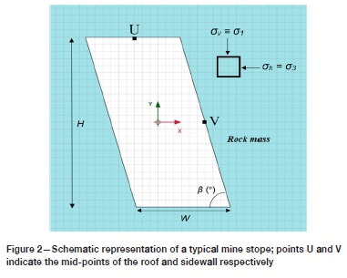
Figure 2 shows a typical mine stope consisting of a horizontal roof, a horizontal base and two parallel and inclined walls. In the figure, W and H are the width and height of the stope, respectively; ß is the inclination angle of the stope walls; σv and σhon the stress block represent the vertical and horizontal natural in-situ principal stresses, respectively; the out-of-plane stress is another in-situ principal stress. The mid-points have been denoted as U and V on the surfaces of roof and sidewall respectively.
The numerical code Plaxis 2D (Brinkgreve and Vermeer 1999), based on the finite element method and commonly adapted for rock mechanics and geotechnical engineering, is used here to evaluate the stresses around mine stopes. The sign convention used by Plaxis 2D considers compression negative (-) and tension positive (+). However, the results presented in this study follow the sign convention commonly used in rock mechanics analysis, where compression is positive (+) and tension is negative (-).
The linearly elastic model of Plaxis 2D was first validated by comparing the simulated stresses against the analytical solutions for a circular opening (Kirsch, 1898; Hiramatsu, 1962; Hiramatsu and Oka, 1968; Li, 1997). Additional validations were made against the graphical and analytical solutions of Hoek and Brown (1980) in the cases of elliptical and square openings. More details are presented in Pagé (2018).
Table I presents the program of numerical simulations. Forty-eight stope geometries were considered by combining the stope width (W), height (H), and wall inclination angle (ß). Two regimes of natural in-situ stresses were considered: Case 1 with σv= 30 MPa and σh= 0; Case 2 with σv= 0 and σh= 30 MPa. It should be noted that the consideration of a zero horizontal in-situ stress ahin Case 1 and a zero vertical in-situ stress σv in Case 2 is necessary for applying the principle of superposition. This does not mean that the numerical models only correspond to zero vertical or horizontal in-situ stress, although the models remain valid for such extreme cases. The principal stresses tangential to the exposed faces at points U and V (on the wall surfaces) are calculated (see Figure 2).
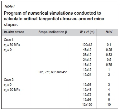
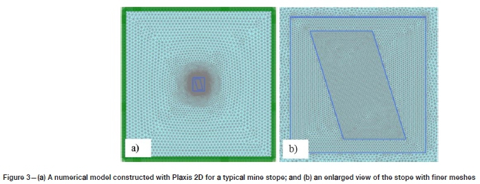
Figure 3 shows a numerical model constructed with Plaxis 2D. An enlarged view of the stope with refined meshes around the stope before excavation is presented. The natural in-situ stresses were first initiated over the entire model. The four outer boundaries were then fixed in all directions. Finally, the excavation of the stope was simulated. For each numerical model with a new stope geometry, domain and meshes sensitivity analyses have been done to ensure that the outer boundaries are far enough from the stope and the meshes around the stope are fine enough. A sufficiently large domain is necessary to avoid the boundary effect, while finer meshes around the stope are required to ensure stable numerical results (see more details presented in Pagé, 2018).
Figure 4 presents the minor (σ3, Figure 4a) and major (σ1, Figure 4b) principal stresses contours around a stope with H/W = 2 and ß = 75°, obtained from numerical modelling using an in-situ stress state of σv= 30 MPa and σh= 0 MPa (with σv= -30 MPa and σh= 0 MPa as inputs to Plaxis 2D). Note that the major and minor in-plane principal stresses in Plaxis 2D are represented by σ1 and σ3 respectively, while the out-of-plane principal stress is denoted by σ2. Figure 4a shows that the critical tangential stresses on the roof are under tension (positive in Plaxis 2D), while Figure 4b indicates that the critical tangential stresses on the walls undergo compression (negative in Plaxis 2D). The minor principal stress at the roof centre is -26.8 MPa (in tension), while the major principal stress at the mid-height of the hangingwall and footwall is 37.4 MPa (in compression).
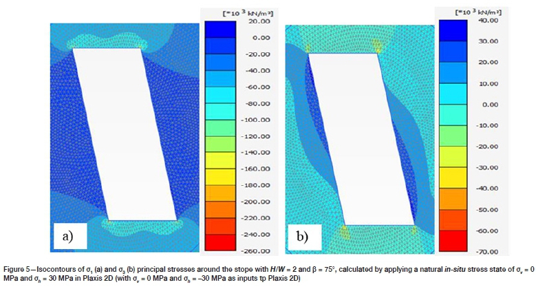
Figure 5 shows the major (σ1, Figure 5a) and minor (σ3, Figure 5b) principal stress contours around the stope with H/W = 2 and ß = 75°, obtained by numerical modelling with a natural in-situ stress state of σv= 0 MPa and σh= 30 MPa (with σv= 0 MPa and σh= -30 MPa as inputs to Plaxis 2D). In this case, the critical tangential stress on the roof is under compression (negative in Plaxis 2D) based on the major principal stress (oj, Figure 5a), while the critical tangential stresses on the walls are under tension (positive in Plaxis 2D) based on the minor principal stress (σ3, Figure 5b). The major principal (compressive) stress at the roof centre is 61.1 MPa, while the minor principal (tensile) stress at the mid-height of the hangingwall and footwall is -23.6 MPa.
Proposed semi-empirical solution
Formulation
To formulate a semi-empirical solution for evaluating the elastic stresses around mine stopes, one uses the principle of superposition valid in elasticity theory for homogenous, isotropic, and linearly elastic material. For a given stope geometry, the stresses around the opening are investigated by applying a horizontal natural in-situ stress. The induced stresses at the point of interest on the stope wall are then normalized by the applied horizontal natural in-situ stress. By changing the stope height to width ratio (H/W) and wall inclination angle (ß), a relationship based on curve fitting can then be established between the studied stresses at the point of interest on the stope wall and the horizontal natural in-situ stress, stope width to height ratio, and stope wall inclination angle.
The same process is repeated for the vertical natural in-situ stress with different stope width to height ratios and stope wall inclination angles. Applying the curve-fitting technique leads to another equation, which describes the induced stress around the stope opening as a function of the vertical natural in-situ stress, stope width to height ratio, and stope wall inclination angle.
By adding the two equations, one obtains an equation that describes the studied stresses at the point of interest on the wall or roof as a function of the horizontal and vertical natural in-situ stresses, stope geometry, and wall inclination. The procedure can be summarized as follows:
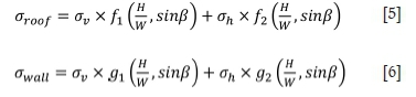
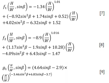
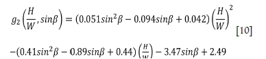
where f1 and f2 are the geometric functions on the critical tangential stress at the roof centre, associated with the vertical and horizontal natural in-situ stresses, respectively; g1 and g2
are the geometric functions on the critical tangential stress at the mid-height of the hangingwall and footwall, associated with the vertical and horizontal natural in-situ stresses, respectively.
To obtain the four geometric functionsf1,f2, g1, and g2, a second-degree polynomial regression fit (for both/j and f2), and a combination of a power regression fit and a second-degree polynomial regression fit (for g1 and g2 respectively) were applied to the numerical results of the critical induced stresses at the roof centre and at the mid-height of the wall as a function of the H/W ratio, separately for ß = 90°, 75°, 60°, and 45°. Figure 6 shows the four geometric functions (tendency curves in dotted lines) as a function of H/W for ß = 90° (Figure 6a), 75° (Figure 6b), 60° (Figure 6c), and 45° (Figure 6d).
A second calibration of these four geometric functions by considering the wall inclination angle leads to the following equations: Equations [5] to [10] constitute the proposed solution for estimating the elastic stresses at the roof centre and mid-height of the hangingwall and footwall around typical mine stopes. These equations are independent of the stope depth and rock mass strength.
When the natural in-situ stress state is σv> 0 (in compression) and σh= 0, the solution predicts tension (σroof < 0) acting on the roof and compression (σwall > 0) on the mid-height of the walls. Conversely, when the natural in-situ stress state is σv= 0 and σh> 0 (in compression), the solution leads to compression (σroof > 0) on the roof and tension (σwall < 0) on the mid-height of the walls.
Figure 6 shows that the critical induced stresses at the roof centre and at the mid-height of the hangingwall and footwall calculated by the proposed solution (Equations [5] to [10]), and represented by the full lines, correspond well to those obtained by the numerical modelling. This type of comparison between a proposed solution and numerical (or experimental) results, which is used in the calibration or curve fitting to obtain the required parameters, is usually considered as validation or prediction. This is, however, not true. The validity and predictability of the calibrated model (obtained by calibration or curve filling) should be tested against additional and different numerical (or experimental) results.
Validation and predictability
To test the validity and predictability of the proposed solution, additional numerical simulations were performed by considering more stope geometries and virgin in-situ stress states.
Figure 7 shows the variation of the induced tangential stresses, obtained by numerical modelling and predicted by the proposed semi-empirical solution, at the roof centre and at mid-height of the walls, for an isotropic natural in-situ stress state of 30 MPa (compression) and stopes having wall inclination angles ß = 90°, 75°, 60°, and 45° and H/W ratio varying from 0.1 to 10. It is seen that the agreement between these two different approaches is excellent.
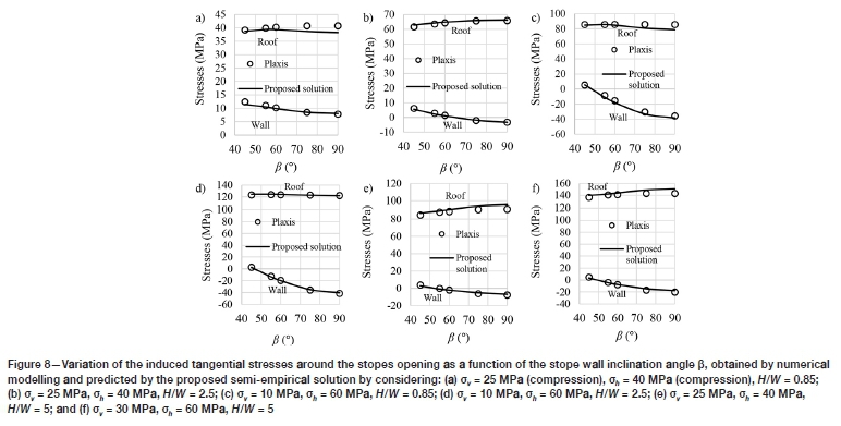
Figure 8 presents another validation and test of predictability of the proposed semi-empirical solution using additional numerical simulations conducted with anisotropic in-situ stresses as the stope wall inclination angle ß varies from 90° to 45°. Once again, good agreement is obtained between the numerical and theoretical results for the case of σv= 25 MPa (compression), σh = 40 MPa (compression), H/W = 0.85 (Figure 8a), σv= 25 MPa, σh= 40 MPa, H/W = 2.5 (Figure 8b), σv= 10 MPa, σh= 60 MPa, H/W = 0.85 (Figure 8c), σv= 10 MPa, σh= 60 MPa, H/W = 2.5 (Figure 8d), σv= 25 MPa, σh= 40 MPa, H/W = 5 (Figure 8e), and σv= 30 MPa, σh= 60 MPa, H/W = 5 (Figure 8f).
The proposed solution can thus be considered as validated. It can then be used to calculate the stresses and the stress factor A for the case of typical mine stopes with any inclination angle and height to width ratio under any in-situ stress state.
Sample application
In the following, a sample calculation is presented to further illustrate the application of the proposed solution (Equations [5] to [10]).
It is planned to mine out a 6 m (W) wide ore vein inclined at 67° (ß), with a 30 m (H) high stope located 500 m below the ground surface. The vertical in-situ stress can be estimated based on the overburden depth, while the horizontal in-situ stress is 1.67 times the vertical in-situ stress. These parameters give the following in-situ stress state and stope geometry:
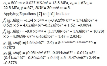
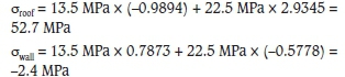
By applying Equations [5] and [6], the principal stresses induced on the roof and wall of the stope can be obtained as follows:
Discussion
Numerical modelling requires the availability of pertinent software and hardware and qualified modellers who know how to correctly conduct numerical modelling. Currently, the availability of computation resources in terms of hardware and software is no longer an issue, and numerical modelling has become a common practice for various research and design projects. However, knowing how to use a numerical code is often considered equivalent of knowing how to correctly perform numerical modelling. This can partly explain the crisis of confidence in numerical modelling and why many modellers do not believe in even their own numerical results. In fact, knowing how to use a numerical code is totally different from knowing how to conduct numerical modelling. The former needs only short training (a couple of hours) while the latter requires much more advanced training and rich experience in order to obtain stable and reliable numerical outcomes (Chapuis et al., 2001; Barbour and Krahn 2004; Cheng, Lansivaara, and Wei, 2007; Diederichs et al., 2007; Krahn 2007; Chapuis, 2012a, 2012b; Duncan 2013).
This work is partly motivated by a perception that the Mathews-Potvin method was considered useless for stope analysis, and that the stability and the maximum dimensions of the stopes can be directly analysed using numerical models, instead of determining the stress factor A and applying the Mathews-Potvin method. It should be recalled that the empirical Mathews-Potvin method was based on many case study observations. The numerical models performed to determine the stress factor A are very simple, considering only an isolated opening around a homogenous, isotropic, and linearly elastic rock. The effectiveness of the method has been proven, especially when it is used as a starting point for the determination of stope dimensions in the preliminary stage of mining projects. When numerical modelling is conducted for stope stability analysis, the models are usually much more complex in terms of stope geometry, mining sequence, and material parameters. Calibrations using field data/observations can be necessary to find the required (but unknown) parameters. In the preliminary stage of a mining project, little field data and information are available to allow the construction and calibration of such sophisticated numerical models.
All of these considerations indicate that the Mathews-Potvin method is very useful at the beginning of a mining project, where it can provide a quick and preliminary estimation of the dimensions of stopes. The necessity for more sophisticated numerical modelling at the advanced stage of a mining project does not invalidate the Mathews-Potvin method. Rather, the Mathews-Potvin method can be more appealing if theoretical or graphical solutions are available for estimating the induced stresses around inclined mine stopes. To this end, a semi-empirical solution has been proposed in which curve-fitting techniques are applied against numerical modelling and the principle of superposition of linearly elasticity theory. The results show that the proposed semi-empirical solution can be used to evaluate the induced principal stresses at the roof centre and mid-height of the wall around typical mine stopes. However, one should keep in mind that the numerical models presented in this study contain several assumptions.
First, a limitation of the numerical models is associated with the 2D plane strain conditions. The numerical results and the proposed semi-empirical solution are valid only when the stope is very long in one horizontal direction. In an actual mine, this is not always the case. Graphical solutions have been presented by Mawdesley, Treman, and Whiten (2001) and Vallejos, Delonca, and Perex (2017) for 3D vertical stopes. Further work is necessary to consider three-dimensional inclined stopes.
The assumption of a linearly elastic rock mass can be held true at relatively shallow depths. At greater depths (deep mines), the behaviour of rocks and rock masses may change to a nonlinear and non-elastic behaviour. Consequently, the validity of the empirical relationships proposed here may be limited to a certain depth. Additional studies could be conducted to formulate similar empirical relationships in nonlinear rock masses.
Another limitation of the proposed semi-empirical relationships is related to the stope geometry. The stopes considered here have a parallel hangingwall and footwall as well as parallel roof and floor. In practice, stopes with nonparallel walls are commonly encountered. More work is needed to propose solutions for estimating the stresses around stopes with nonparallel walls.
In this study, the vertical and horizontal in-situ stresses were considered to be two principal stresses, implicitly assuming that the out-plane in-situ stress is another principal stress. In practice, the vertical in-situ stress and the two horizontal in-situ stresses could form three normal stresses. Further work is thus necessary to develop a more general solution.
Finally, it is very important to point out that the stress factor A defined in the Mathews-Potvin method corresponds to the maximum induced principal stresses on the exposed faces. However, as shown in Figures 4 and 5, the maximum compressive stresses are close to the four corners rather than at the roof centre. We believe that an accurate estimation of the maximum principal compressive stress at stope corners is difficult and unnecessary due to stress concentration - therefore the critical locations in terms of compression should be at the centre, not the stope corners. For tension, as Figure 5b shows, the largest tensile stresses are located near (but somehow distant from) the stope corners, which correspond to the critical locations (rather than the roof or wall centre). In this study, the maximum tensile stress is not considered as its location varies when the stope geometry or natural in-situ stresses change. This renders the formulation very difficult. More work is needed on this aspect. Nonetheless, given the empirical nature of the Mathews-Potvin method and the still limited considerations of the tensile stresses in applying the method, the proposed solutions can provide useful estimation of stresses for application of the Mathews-Potvin method.
Conclusions
The well-known Mathews-Potvin method is an important design tool for mining engineers. However, the application of this method requires the determination of the induced stresses (and stress factor A) around inclined mine stopes using numerical modelling, as few graphical or theoretical solutions are available for such purposes. To overcome this limitation, a semi-empirical solution has been proposed to estimate the induced principal stresses at the roof centre and mid-height of the walls around mine stopes, by applying the superposition principle of linearly elasticity theory and curve-fitting techniques to numerical results. The validity and the predictive capability of the proposed solution have been verified by additional numerical simulations. The proposed semi-empirical solution can thus be used to evaluate the induced tangential stresses at the roof centre and mid-height of the walls around mine stopes with any inclination angles, height to width ratios, and in-situ stress states, as long as the values of H/W are in the range from 0.1 to 10 and ß in the range from 45° to 90°. With these empirical expressions, the stress factor A, a key parameter used in the Mathews-Potvin method, can be determined without conducting numerical modelling.
Acknowledgments
The authors acknowledge the financial support from the Natural Sciences and Engineering Research Council of Canada (NSERC 402318), Fonds de recherche du Quebec - Nature et Technologies (FRONT 2015-MI-191676), Mitacs Elevate Postdoctoral Fellowship (IT08484), and the partners of the Research Institute on Mines and Environment (RIME UQAT-Polytechnique; http://rime-irme.ca/).
References
Barbour, S.L. and Krahn, J. 2004. Numerical modelling - Prediction or process. Geotechnical News, vol. 22, no. 4. pp. 44-52. [ Links ]
Barton, N., Lien, R., and Lunde, J. 1974. Engineering classification of rock masses for the design of tunnel support. Rock Mechanics, vol. 6, no. 4. pp. 189-236. [ Links ]
Bewick, R. and Kaiser, P.K. 2009. Numerical assessment of factor B in Mathews' method for open stope design. Proceedings of the 3rd Canada-US Rock Mechanics Symposium, May 2009, Toronto, Canada. Diederichs, M. and Grasselli, G. (eds). pp. 89-90. [ Links ]
Brady, B.H. and Brown, E.T. 2013. Rock Mechanics for Underground Mining. Springer Science and Business Media, Berlin. [ Links ]
Brinkgreve, R.B.J. and vermeer, P.A. 1999. Plaxis Finite Element Code for Soil and Rock Analysis. Plaxis BV, Delft, The Netherlands. [ Links ]
Capes, G.W. 2009. Open stope hangingwall design based on general and detailed data collection in unfavourable hangingwall conditions. PhD thesis, University of Saskatchewan, Canada. [ Links ]
Chapuis, R.P. 2012a. Influence of element size in numerical studies of seepage: small-scale details. Geotechnical News, vol. 30, no. 1. pp. 32-35. [ Links ]
Chapuis, R.P. 2012b. Influence of element size in numerical studies of seepage: unsaturated zones, steady-state. Geotechnical News, vol. 30, no. 3. pp. 27-30. [ Links ]
Chapuis, R.P., Chenaf, d., Bussière, B., Aubertin, M., and Crespo, R. 2001. A user's approach to assess numerical codes for saturated and unsaturated seepage conditions. Canadian Geotechnical Journal, vol. 38, no. 5. pp. 1113-1126. [ Links ]
Cheng, Y.M., Lansivaara, T., and Wei, W.B. 2007. Two-dimensional slope stability analysis by limit equilibrium and strength reduction methods. Computers and Geotechnics, vol. 34, no. 3. pp. 137-150. [ Links ]
Clark, L.M. AND Pakalnis, R.C. 1997. An empirical design approach for estimating unplanned dilution from open stope hangingwalls and footwalls. Proceedings of the 99th Annual General Meeting. Canadian Institute of Mining, Metallurgy and Petroleum, Vancouver, Canada. [ Links ]
Diederichs, M.S. and Kaiser, P.K. 1999. Tensile strength and abutment relaxation as failure control mechanisms in underground excavations. International Journal of Rock Mechanics and Mining Sciences, vol. 36, no. 1, pp. 69-96. [ Links ]
Diederichs, M.S., Kaiser, P.K., and Eberhardt, E. 2004. Damage initiation and propagation in hard rock during tunnelling and the influence of near-face stress rotation. International Journal of Rock Mechanics and Mining Sciences, vol. 41, no. 5. pp. 785-812. [ Links ]
Diederichs, M.S., Lato, M., Hammah, R., and Quinn, P. 2007. Shear strength reduction SSR approach for slope stability analyses. Proceedings of the 1st Canada-US Rock Mechanics Symposium, Vancouver, Canada. Eberhardt, E., Stead D., and Morrison T. (eds).Taylor & Francis, London. pp. 319-327. [ Links ]
Duncan, J.M. 2013. Slope stability then and now. Proceedings of Geo-Congress 2013, San Diego, California, 3-7 March 2013 Vol. 3. Stability and Performance of Slopes and Embankments., Geo-Institute of ASCE, Reston, VA. pp. 2184-2203. [ Links ]
Exadaktylos, G.E. and Stavropoulou, M.C. 2002. A closed-form elastic solution for stresses and displacements around tunnels. International Journal of Rock Mechanics and Mining Sciences, vol. 39, no. 7. pp. 905-916. [ Links ]
Gerçek, H. 1997. An elastic solution for stresses around tunnels with conventional shapes. International Journal of Rock Mechanics and Mining Sciences, vol. 34, no. 3-4. pp. 96-e1. [ Links ]
Germain, P, and Hadjigeorgiou, J. 1998. Influence of stope geometry on mining performance. Proceedings of the CIM AGM, Montreal, Canada. [CD-ROM] [ Links ]
Hadjigeorgiou, J., Leclair, J., and Potvin, Y. 1995. An update of the stability graph method for open stope design. Proceedings of the CIM Rock Mechanics and Strata Control Session, Halifax, Nova Scotia, Canada. Canadian Institute of Mining, Metallurgy, and Petroleum, Montreal. pp. 14-18. [ Links ]
Hiramatsu, Y. 1962. Stress around a shaft or level excavated in ground with a three-dimensional stress state. Memoirs of the Faculty of Engineering, Kyoto University, vol. 24, no. 1. [ Links ]
Hiramatsu, Y. and Oka, Y. 1968. Determination of the stress in rock unaffected by boreholes or drifts, from measured strains or deformations. International Journal of Rock Mechanics and Mining Sciences and Geomechanics Abstracts, vol. 5, no. 4. pp. 337-353. [ Links ]
Hoek, E., and Brown, E.T. 1980. Underground Excavations in Rock. Institution of Mining and Metallurgy, London. [ Links ]
Hutchinson, D.J. and Diederichs, M.S. 1996. Cablebolting in Underground Mines. BiTech Publishers, Richmond, BC. [ Links ]
Kaiser, P.K., Falmagne, v., Suorineni, F.T., Diederichs, M.S., and Tannant, D.D. 1997. Incorporation of rock mass relaxation and degradation into empirical stope design. Proceedings of the 99th CIM Annual General Meeting, Vancouver, Canada, vol. 15. Canadian Intsitute of Mining, Metallurgy, and Petrolerum, Montreal. [ Links ]
Kirsch, C. 1898. Die theorie der elastizitat und die bedurfnisse der festigkeitslehre. Zeitschrift des Vereines Deutscher Ingenieure, vol. 42. pp. 797-807. [ Links ]
Krahn, J. 2007, May. Limit equilibrium, strength summation and strength reduction methods for assessing slope stability. Proceedings of Rock Mechanics: Meeting Society's Challenges and Demands, Eberhardt, E., Stead D., and Morrison T. (eds). Taylor & Francis, London pp. 311-318. [ Links ]
Li, I. 1997. Étude expérimentale du comportement hydromécanique d'une fracture. PhD thesis, Université Paris 7, France. [ Links ]
Li, I. and Ouellet, S. 2009. Analyse préliminaire pour le dimensionnement des travaux souterrains. ProjetBracemac-McLeod, Report submitted to Xstrata Zinc. [ Links ]
Logie, e.V. and van Tonder, C.P.G. 1967. Stress distribution and potential fracture zone around rectangular, elliptical and circular opening in biaxial stress fields. Report MEG 575, Rock Mechanics Division, National Mechanical Engineering Research Institute, CSIR, Pretoria. [ Links ]
Madenova, Y and Suorineni, F.T. 2020. On the question of original versus modified stability graph factors - A critical evaluation. Mining Technology, vol. 129, no. 1. pp. 40-52. [ Links ]
Mathews, K.E., Hoek, E., Wyllie, D.C., and Stewart, S. 1981. Prediction of stable excavation spans for mining at depths below 1000 m in hard rock. CANMET DSS Serial No: 0sQ80-00081. Ottawa. [ Links ]
Mawdesley, C., Trueman, R., and Whiten, W.J. 2001. Extending the Mathews stability graph for open-stope design. Mining Technology, vol. 110, no. 1. pp. 27-39. [ Links ]
Milne, D., Pakalnis, R.C., and Felderer, M. 1996. Surface geometry assessment for open stope design. Rock Mechanics: Proceedings of the 2nd North American Rock Mechanics Symposium, Montreal, Quebec 19-21 June 1996. Vol. 1. American Rocck Mechanics Association, Alexandria, VA. pp. 315-322. [ Links ]
Nickson, S.D. 1992. Cable support guidelines for underground hard rock mine operations. PhD thesis, University of British Columbia, Canada. [ Links ]
Page, P. 2018. Evaluation numérique de la stabilité des chantiers: Contraintes élastiques autour des chantiers et résistance nécessaire des semelles en remblai cimenté. MS thesis, École Polytechnique Montréal, Canada [ Links ]
Papaioanou, A. and Suorineni, F.T. 2016. Development of a generalised dilution-based stability graph for open stope design. Mining Technology, vol. 125, no. 2. pp. 121-128. [ Links ]
Potvin, Y. 1988. Empirical open stope design in Canada. PhD thesis, University of British Columbia, Canada. [ Links ]
Potvin, Y., Hudyma, M., and Miller, H.D.S. 1989. Design guidelines for open stope support. CIM Bulletin, vol. 82, no. 926. pp. 53-62. [ Links ]
Potvin, Y., and Milne, D. 1992. Empirical cable bolt support design. Rock Support in Mining and Underground Construction: Proceedings of the International Symposium on Rock Support. Balkema, Rotterdam. pp. 269-275. [ Links ]
Scoble, M.J., and Moss, A. 1994. Dilution in underground bulk mining: implications for production management. Geological Society, Special Publications, London, vol. 79, no. 1. pp. 95-108. [ Links ]
Stewart, S.B.V. and Forsyth, W.W. 1995. The Mathew's method for open stope design. CIM Bulletin, vol. 88, no. 992. pp. 45-53. [ Links ]
Stewart, P.C. and Trueman, R. 2001. The extended Mathews stability graph: Quantifying case history requirements and site-specific effects. Proceedings of the International Symposium on Mining Techniques, Val d-Or, Quebec, Canada. Canadian Institute of Mining, Metallurgy, and Petroleum, Montreal. pp. 84-92. [ Links ]
Sunwoo, C., Jung, Y.B., and Karanam, U.R. 2006. Stability assessment in wide underground mine openings by Mathews' stability graph method. Tunnelling and Underground Space Technology, vol. 21, no. 3. pp. 246. [ Links ]
Suorineni, F.T. 1998. Effects of faults and stress on open stope design. PhD thesis, University of Waterloo, Canada. [ Links ]
Suorineni, F.T. 2010. The stability graph after three decades in use: experiences and the way forward. International Journal of Mining, Reclamation and Environment, vol. 24, no. 4. pp. 307-339. [ Links ]
Suorineni, F.T. 2012. A critical review of the stability graph method for open stope design. MassMin 2012: Proceedings of the 6th International Conference & Exhibition on Mass Mining, Sudbury, Ontario, 10-14 June 2012. Canadian Institute of Mining, Metallurgy, and Petrolerum, Montreal. pp. 10-14. [ Links ]
Suorineni, F.T., Tannant, D.D., and Kaiser, P.K. 1999a. Determination of fault-related sloughage in open stopes. International Journal of Rock Mechanics and Mining Sciences, vol. 36, no. 7. pp. 891-906. [ Links ]
Suorineni, F.T., Tannant, D.D., and Kaiser, P.K. 1999b. Fault factor for the stability graph method of open-stope design. Transactions of the Institution of Mining and Metallurgy Section A: Mining Industry, vol. 108. pp. A92-A104. [ Links ]
Suorineni, F.T., Henning, J.G., and Kaiser, P.K. 2001a. Narrow-vein mining experiences at Ashanti: case study. Proceedings of the International Symposium on Mining techniques of Narrow-vein Deposits, Val-dOr, QC, Canada. pp. 57-62. Canadian Institute of Mining, Metallurgy, and Petroleum, Montreal. [ Links ]
Suorineni, F.T., Tannant, D.D., and Kaiser, P.K. 2001b. Likelihood statistic for interpretation of the stability graph for open stope design. International Journal of Rock Mechanics and Mining Sciences, vol. 38, no. 5. pp. 735-744. [ Links ]
Suorineni, F.T., Tannant, D.D., Kaiser, P.K., and Dusseault, M.B. 2001. Incorporation of a fault factor into the stability graph method: Kidd mine case studies. Mineral Resources Engineering, vol. 10, no. 1. pp. 3-37. [ Links ]
Trueman, R., Mikula, P., Mawdesley, C., and Harries, N. 2000. Experience in Australia with the application of the Mathews' method for open stope design. CIM Bulletin, vol. 93, no. 1036. pp. 162-167. [ Links ]
Trueman, R. and Mawdesley, C. 2003. Predicting cave initiation and propagation. CIM Bulletin, vol. 96, no. 1071. pp. 54-59. [ Links ]
Vallejos, J.A., Delonca, A., and Perez, E. 2017. Three-dimensional effect of stresses in open stope mine design. International Journal of Mining, Reclamation and Environment, vol. 32, no. 5. pp. 355-374. [ Links ]
Wang, J. 2004. Influence of stress, undercutting, blasting and time on open stope stability and dilution. PhD thesis, University of Saskatchewan, Canada. [ Links ]
Zhang, Y., Hughes, R., and Mitri, H.S. 2011. Modified stability graph method with a new rock stress factor. Proceedings of the 45th US Rock Mechanics/ Geomechanics Symposium. San Francisco, California, 26-29 June 2011. American Rock Mechanics Association, Alexandria, VA. [ Links ]
 Correspondence:
P. Yang
Email: pengyu.yang@polymtl.ca
Received: 27 Mar. 2019
Revised: 13 May 2021
Accepted: 30 Jun. 2021
Published: August 2021

