


Serviços Personalizados
Artigo
 Inglês (pdf)
 Artigo em XML
 Referências do artigo
Indicadores

Links relacionados
-
 Citado por Google
 -
 Similares em Google
Compartilhar

 Permalink
Journal of the Southern African Institute of Mining and Metallurgy
versão On-line ISSN 2411-9717
versão impressa ISSN 2225-6253
J. S. Afr. Inst. Min. Metall. vol.121 no.6 Johannesburg Jun. 2021
http://dx.doi.org/10.17159/2411-9717/951/2021
PROFESSIONAL TECHNICAL AND SCIENTIFIC PAPERS
Investigation of the mechanism for fireside corrosion in coal-fired boilers in South Africa
K.G. MolokoI, II; J.W. van der MerweI
ISchool of Chemical and Metallurgical Engineering, Faculty of Engineering and Built Environment, University of the Witwatersrand, Johannesburg, South Africa
IIEskom, Research & Innovation Centre, Johannesburg, South Africa
SYNOPSIS
Furnace wall tubes from 600 MW subcritical boilers at three coal-fired power stations were sampled and the fireside deposits examined to determine the mechanism of fireside corrosion. This involved an in-depth investigation into the morphology and composition of the fireside deposits and the conditions of the furnace that enable this type of attack. SEM-EDS analysis revealed high concentrations of oxygen, iron, and sulphur, QEMSCAN and XRD analyses identified the presence of Fe3O4, Fe2O3, FeS, and FeS2. Differential thermal analysis showed thermal activities at temperatures of 500-600°C, 900-1100°C, and 1100-1250°C, which are associated, respectively, with FeS2 oxidation to FeS and Fe2O3, at 475-525°C, formation of aluminosilicates at 925-1100°C, and melting of FeS around 1190°C. The absence of sodium and potassium eliminates the contribution of molten alkali sulphates to the corrosion. The consistent coexistence of iron sulphide and iron oxide is indicative of the substoichiometric conditions in the furnace, while the detection of pyrite suggests that the coal is not completely combusted, which points to a poor combustion process. These observations were affirmed by gas analysis at one of the stations, where very high levels of carbon monoxide were measured at the furnace wall (> 14 000 ppm) and furnace exit (> 3500 ppm). The high CO concentrations are indicative of limited combustion caused by limited O2. These reducing conditions promote the formation of FeS-rich deposit, which is the corrosive species responsible for degradation.
Keywords: fireside corrosion, sulphidation, coal-fired boiler, furnace wall tubes.
Introduction
Fireside corrosion is the metal loss from tubes due to chemical attack on the fireside of heat exchanging surfaces in fossil fuel-fired furnaces. It is due to high temperatures and the unique environment encountered in the furnaces, which is caused by the complex interaction of the combustion gases at temperatures varying between 400 and 1200°C (Syed, Simms, and Oakey, 2011), the distribution of pulverized fuel, elements released from the fuel, the type and nature of the ash carried over in the gas stream, and the materials of construction of the boiler.
Fireside corrosion in boilers is commonly divided into two categories by location, namely furnace wall corrosion in the lower furnace and fuel ash corrosion of superheaters in the upper furnace. This type of corrosion was first recognized as a serious problem in the early 1940s, when some of the power stations in the USA using pulverized coal-fired furnaces, experienced an increased number of furnace wall tube failures (Harb and Smith, 1990). In South Africa, the corrosion phenomenon was identified in the early 1990s when a few coal-fired subcritical boilers (600 MW units) suffered damage and tube failures in the furnace area.
Despite efforts to manage the effects of fireside corrosion, through (i) measuring and monitoring of the remaining wall thickness of the tubes by ultrasonic tests during unit outages and (ii) replacing tubing below the minimum wall thickness, the level and extent of damage have been increasing and resulting in high costs and extensive outage times. In addition, future trends such as the installation of low-NOx burners to control SOx and NOx emissions and an increase in the steam temperatures to raise the thermal efficiency, i.e. through the construction of supercritical boilers, are likely to increase fireside corrosion within Eskom boilers, as has been seen in other power plants globally (Bakker, 1998; Hatt, 1990). To comply with air pollution control legislation, coal-fired power generation industries have found it necessary to apply technologies that reduce NOx and SOx emissions. Low excess air combustion and two-stage combustion are commonly applied as means of realizing low-NOx combustion (Bakker, 1998; Dooley and MacNaughton, 2007). Although these combustion methods can reduce NOx emissions from a boiler, a strong reducing atmosphere is formed in the region between the burners and air ports in the case of two-stage combustion. This atmosphere promotes the formation of hydrogen sulphide (H2S), which causes sulphidation corrosion at the boiler wall (Bakker, 1998; Dooley and MacNaughton, 2007). In addition, to meet the high demand for electricity, supercritical boilers are increasingly being introduced. At higher temperatures, boiler tubes are at a higher risk of suffering high-temperature corrosion, which includes fireside corrosion.
Owing to the limited knowledge and understanding regarding the actual mechanisms of this phenomenon in Eskom coal-fired boilers, this investigation was initiated with the aim of determining the mechanism of fireside corrosion and the drivers of and contributors to the phenomenon. The investigation was aimed at ascertaining:
➤ Whether the fireside corrosion attack within the boiler units of the selected power stations is by sulphidation and/or by formation of low-melting alkali sulphate salts
➤ The influence of the environment in the furnace
➤ The role of the combustion process in promoting the fireside corrosion mechanism.
Experimental procedure
Coal composition and the subsequent release of gaseous, molten, or solid components via the combustion process are primary determinants of the potential severity of fireside corrosion (Dooley and MacNaughton, 2007). The most important corrodents are (i) sulphur, present as sulphur dioxide and sulphur trioxide, or as hydrogen sulphide, (ii) vapours of alkali metal salts in the form of oxides, hydroxides, or sulphates, and (iii) chlorine compounds. Knowing the mineralogy of the ash deposit is important in understanding the fireside deposits and their relationship to corrosion. The mechanism of fireside corrosion was investigated by collecting and evaluating samples of fireside deposit and performing in-situ gas analysis, which due to limited availability of boiler units was applied only on one unit of one power station.
Sampling
During plant shut-downs at three power stations (A, B, and C), tubing samples were removed from the areas that are historically known to suffer from fireside corrosion. The samples were selected using the following criteria:
➤ Tubing that failed during operation
➤ Tubing with wall thicknesses below the required minimum, as measured by ultrasonic testing.
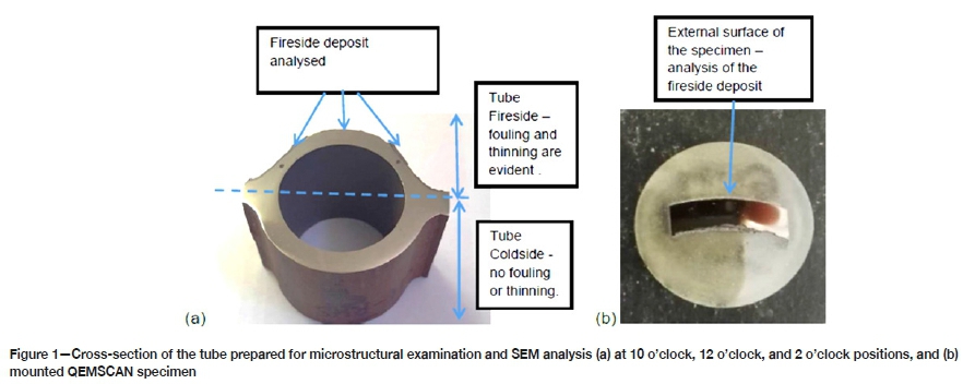
The sampling areas selected were where fireside corrosion-related failures occurred or tube replacements were required due to low remaining wall thicknesses. A minimum of two units per power station were sampled for representability and repeatability of results. Figure 1 shows the areas sampled at the respective power stations.
In order to ensure that the fireside deposit was preserved during sampling, the in-house procedure for cutting, storage, and transportation of samples was applied (Chabula, 2009). The tubes were cut to a minimum of 1 m length with a saw, at a position 300 mm away from damage in order to prevent contamination by debris and overheating. Subsequent to cutting, tubes were marked clearly to show the boiler unit number, location, level, tube number, and sample orientation. The tubes were restricted from movement during transportation in order to avoid spalling of the fireside deposit. The tubes were also kept away from contact with water or any other liquid during storage and transportation.
Sample descriptions
Two sidewall tubes were tested and analysed from units 1, 3, and 4 of power station A, units 1, 3, and 8 of power station B, and units 4 and 6 of power station C.
Condition of the tubes investigated
Specimens were sectioned from the tubes for testing and verification of the material, which was done by means of chemical analysis with spark emission spectroscopy, microstructural examination, and hardness testing with a Leco Macro Vickers hardness tester with an applied load of 10 kg. Verification of calibration was done using a 109 HV10 kg Yamamoto hardness test block. The results obtained were benchmarked against the standard specification BS EN 10216- 2 (2013), which is equivalent to the original code used in the design of the tubes.
Analysis of deposits
Mechanical (cutting and scraping) and metallographic methods (grinding, polishing, and etching) were employed during the preparation of the fireside deposit specimens. The steps in the preparation of specimens were as follows.
➤ Ring samples were cut out to prepare for analysis of the cross-sectional area of the tubes. A Struers Labotom-15 abrasive cutter was used.
➤ Deposit powder was scraped off the tubes using a sharp steel blade.
➤ Tubing cross-sections were ground with silicon carbide paper with grit size ranging from 220 μηι to 2400 μιη.
➤ Ground specimens were subsequently polished with diamond suspension to a surface finish of up to 1 μπι.
➤ After polishing, specimens prepared for microstructural examination were etched with 5% Nital to expose the general microstructure of the material.
The analysis and characterization of the fireside deposits were performed as follows.
➤ Scanning electron microscopy (SEM) with energy-dispersive X-ray spectroscopy (EDX) to map out the concentration and distribution of elements within each layer of the fireside deposit, using an FEI - QUANTA 600 instrument. The fireside deposits were analysed and mapped along the cross-section of the tube. The data from the analysis was processed and interpreted using INCA Feature version 1.1 software. The chemical compositions of the deposits and corrosion products on the metal surfaces were studied using EDX by elemental mapping line profiles.
➤ Chemical date was obtained by Quantitative Evaluation of Minerals By Scanning Electron Microscopy (QEMSCANTM), using a QEMSCAN 650F instrument, and X-ray diffraction (XRD). The data was processed with Discover version 5.3 software.
➤ Differential thermal analysis (DTA) was used to determine the thermal behaviour of the compounds in the fireside deposit. The powder specimens were mounted onto sample holders and analysed by single crystal X-ray diffraction (SC-XRD) with a Bruker D8 Venture Photon CMOS. The data was processed, and interpreted using the Diffrac.Suite EVA version 4.2.2 (Bruker brand) software.
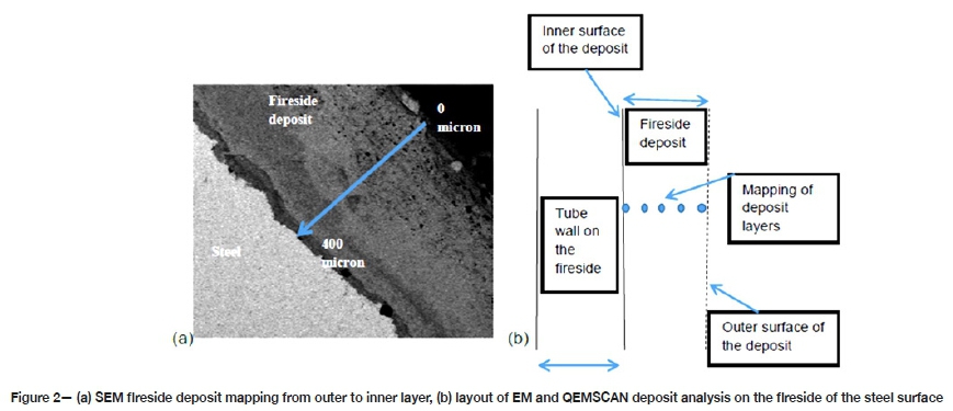
Cross-sections of the tubes with attached fireside deposit were prepared for SEM-EDS and QEMSCAN evaluations as shown in Figure 1. Two tube ring cross-sections were removed from each tube with the deposit still intact. Figure 2 illustrates the way the fireside deposit was analysed and characterized. The cutting was done under dry conditions to avoid contamination from fluids.
Powder samples of at least 3 g (for XRD) and 10 g (for DTA) analyses were obtained by scraping off the fireside deposit. The DTA analysis was performed in alumina crucibles 6 χ 2.5 mm in size. A maximum testing temperature of 1400°C was used with a heating rate of 10°C/min in a nitrogen atmosphere.
In-situ gas analysis
The actual conditions of the flue gas were determined at one boiler, by performing in-situ combustion tests, which involved analysis of the composition of the flue gas, measurements of the tube temperature, and analysis of the distribution of air (or excess oxygen) in the furnace. The in-situ gas analysis was conducted at unit 1 of Station A over a period of three days at different excess air levels with oxygen (O2) at 2.48%, 2.82%, and 3.1% on a dry basis. The in-furnace probing positions were located at gun blower 12 (one of the areas where fireside corrosion has occurred repetitively), the furnace exit, superheater 3, and reheater 2 to cover different levels of the boiler. Temperature traverses were conducted on both the left-hand side (LHS) and right-hand side (RHS) of the economiser inlet and outlet areas. Oxygen and carbon monoxide measurements were taken at the furnace exit (RHS) and both sides of the economiser outlet ducts. The results of the gas analysis were checked against the fireside deposit analysis at the same station to determine the link between the furnace environment and the type of fireside corrosion taking place.
Results
Tube conditions - visual inspection
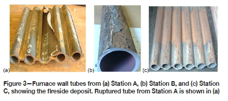
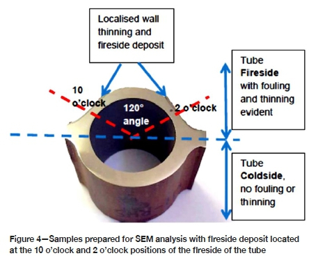
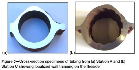
The hard and thick sintered deposits with loosely bonded ash on the fireside of the tubes from the three power stations are shown in Figure 3. The deposit thicknesses were a maximum of 0.975 mm, 0.6 mm, and 0.57 mm for stations A, B, and C respectively. Wall thinning was observed on the cross-sections of the tubes, with the fireside generally showing significant thinning and the cold side exhibiting a uniform wall with minimal thinning. Figures 4 and 5 show the localized wall thinning on the fireside of tubes from stations A and C at the location encompassing a 120° angle of the tube circumferentially (referred to as the 10 o'clock and 2 o'clock positions). One of the ruptured tubes from Station A is shown in Figure 3a. This tube failed due to significant wall thinning and excessive build-up of pressure.
The wall thickness measured on the fireside of Station A tubing varied from 0.1 to 4.93 mm. This implies that the tubes with the original wall thickness of 5.6 mm experienced wall losses ranging from approximately 11.9 to 98.2%. Station C, having tubes, with original wall thickness of 7.5 mm and remaining wall thicknesses of 2.92 to 3.4 mm, experienced relatively lower wall loss, estimated at 45.2 to 65.33%.
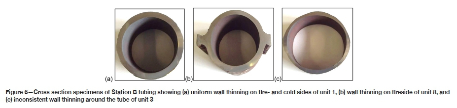
Tubes from Station B showed different features compared to stations A and C. Unit 1 tubes revealed general wall thinning around the circumference. Unit 8 showed wall thinning only on the fireside. Unit 3, on the other hand, showed a completely different picture; inconsistent wall thinning was observed on both the fireside and non-fireside as shown in Figure 6. Observations on tubing from Station B suggest that in addition to fireside corrosion, there may be other forms of attack taking place. Different fireside deposits were also observed on Station B tubing. Units 1 and 3 had hard and thin sintered brown deposits, whereas unit 8 had loosely bonded grey ash deposits. The wall thickness of the tubing from Station B ranged from 1.76 to 5.54 mm. Based on a 6 mm installed wall thickness, the highest wall thinning was measured at 68.57%.
Tube conditions - chemical analysis and hardness measurement
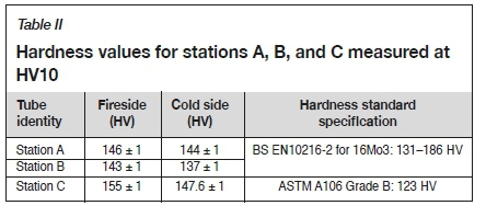
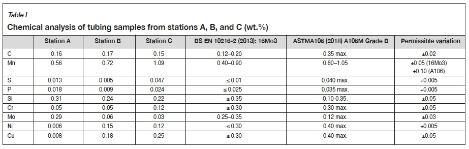
Table I shows compliance between the chemical composition of station A and B tubes and the standard specification of 16Mo3 steel as defined in BS EN 10216-2 (2013). Station C matches the standard specification of St 45.8 as defined in ASTM A106/ A106M (2018). Table II outlines the average hardness of the tubing on the fire- and cold sides, which are similar and well within the specification for 16Mo3 and St 45.8 when converted from ultimate tensile strength of 450-600 MPa and 415 MPa respectively using a conversion guideline in ASTM A370 (2019). The error margin of ±1 HV was measured on the calibration block. The outcome from chemical analysis and hardness tests confirms that the correct material was used, thus the corrosion is mainly due to furnace conditions and less due to the material of the tubes.
Microstructural examination
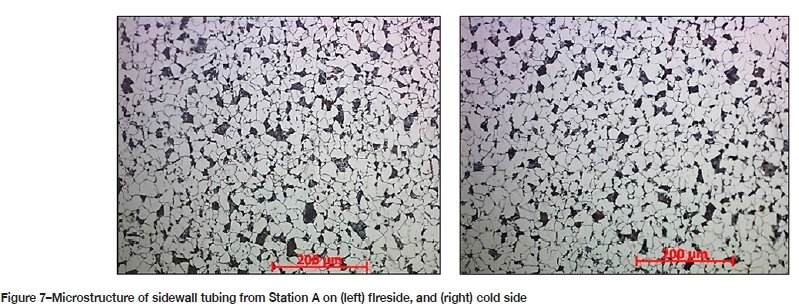
The microstructures observed on tubing samples from the three power stations were the same on both fireside and cold side, as shown in Figure 7. They consisted of well-spheroidized and degenerated carbides, still grouped in the original pearlitic pattern, in a ferrite matrix. A spheroidized microstructure is typical of service-exposed 16Mo3 and A106 Grade B tubing operating at moderately elevated temperatures. A similar appearance between the fireside and cold side indicates that the flame-exposed (fire-) side of the tubing was not significantly hotter than the casing (cold) side.
Deposit analysis
Subsequent to visual inspection and examination under light microscopy, the fireside deposits were analysed with SEM-EDS, SEM-QEMSCAN, XRD, and DTA. The results are presented in the four sections below.
SEM-EDS analysis of the fireside deposit
A three-layered fireside deposit was consistently seen in all the tubing samples from all three power stations, with similar elemental profiles as shown in Figure 8 to 15. A high concentration of oxygen was seen in the thin inner layer -immediately adjacent to the metal, as well as in the outer layer. Sulphur was mostly concentrated in the middle layer. High iron was detected throughout the thickness of the fireside deposit. The distribution of elements was as follows:
➤ Inner layer: High concentration of iron and oxygen and no or traces of sulphur.
➤ Middle layer: Rich in iron and sulphur with low to moderate concentration of oxygen.
➤ Outer layer: High levels of iron and sulphur with low concentration of oxygen and Al, Si, and Ca (fly ash particles).
QEMSCAN
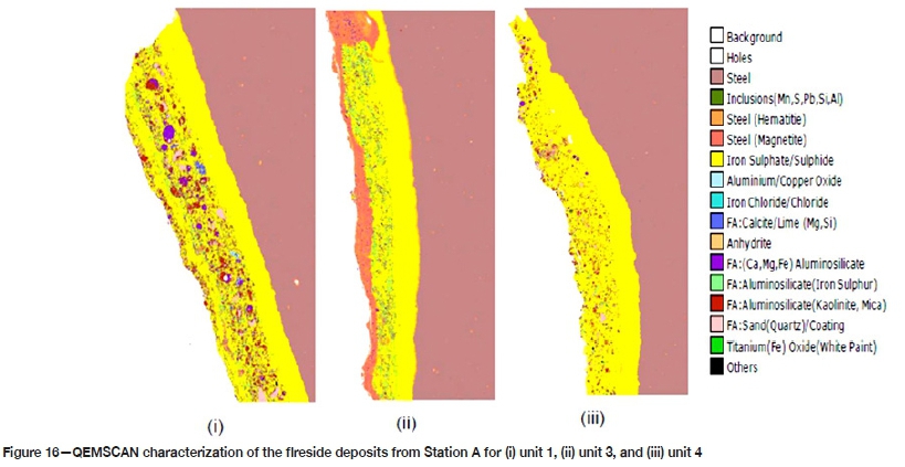
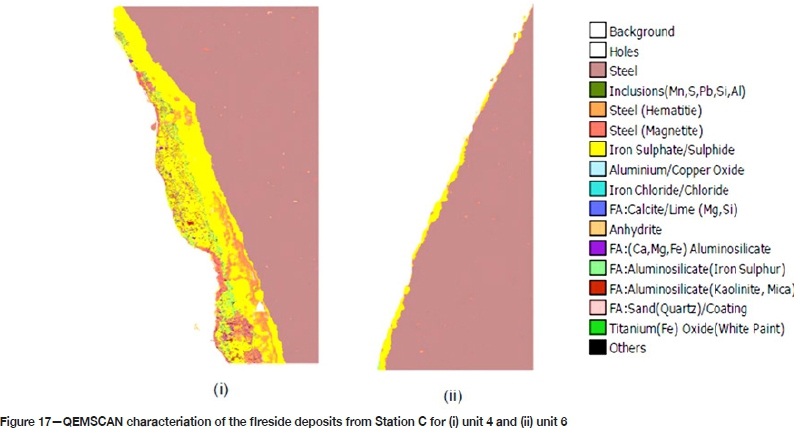
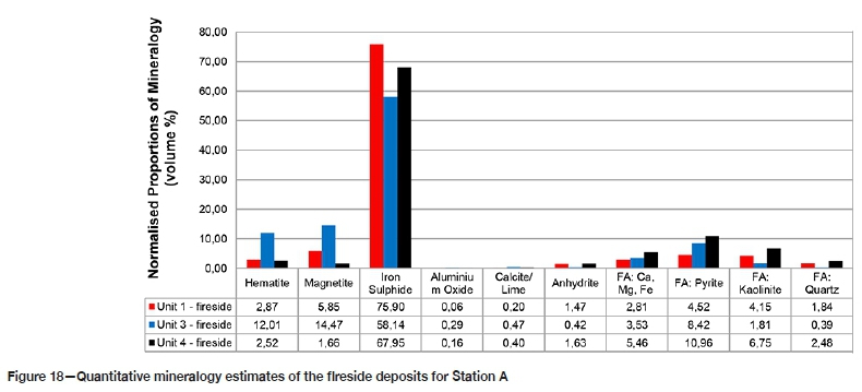
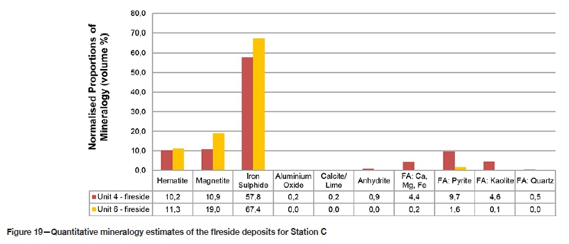
QEMSCAN analysis was performed on the fireside of the tubes from stations A and C. Due to the lack of samples from Station B during this analysis, the mineralogy of Station B tubes was analysed with XRD only. A similar morphology was observed on the fireside deposits from stations A and C. As shown in Figures 16 and 17 respectively, a three-layered deposit with a consistent band of Fe-sulphide rich phase was observed on the interface to the steel extending to the middle section. The outer layer was predominantly iron oxide with fly ash particles: quartz (SiO2), kaolinite (Al2O3.2SiO2.2H2O), Ca/Mg aluminosilicate, and pyrite (FeS2). These results correlate with the high iron and sulphur concentrations in the middle and innermost layers detected by SEM-EDS. Figure 18 and 19 give the mineralogical composition of the fireside deposits from stations A and C respectively. The fireside deposit thickness was measured at a maximum of 1.2 mm for Station A and 0.53 mm for Station C.
There was no evidence of sodium or potassium associated with the sulphur In any of the samples from stations A and C. The presence of sulphide phases coexisting with iron oxide is indicative of substoichiometric conditions in the furnace and/or on the tube surfaces.
X-ray diffraction (XRD)
XRD analysis of the fireside deposits from the three power stations produced correlating results. A high content of haematite and magnetite was detected, with consistent detection of pyrrhotite (FeS). Fly ash particles were also identified (predominantly quartz and mullite) as well as coal constituents such as pyrite, galena, and anglesite (PbSO4).
Station A: The XRD analysis revealed high levels of Fe2O3 and Fe3O4 with pyrrhotite in small quantities (1.4-3.7 wt.%). Small quantities of quartz and mullite (fly ash) were also detected.
Station B: The fireside deposit consisted predominantly of Fe3O4 and low levels of Fe2O3. Iron-sulphur rich phases were detected, and these included pyrrhotite, pyrite, and traces of galena (PbS). Fly ash particles identified include mullite, quartz, and jarosite (K2O-3Fe2O3-4SO3-6H2O). The concentrations of pyrrhotite were wide spread, with 3.7-5.6 wt.% for unit 1 and with 40-50 wt.% for unit 3. The difference in the levels of pyrrhotite for unit 1 and unit 3 may be an indication of the furnaces operating under different combustion conditions, with unit 3 possibly being exposed to prolonged reducing conditions.
Station C: The fireside deposit on the tubes from both units of Station C showed high levels of pyrrhotite. Differences were seen in the concentrations of magnetite; the fireside deposit from unit 6 had higher concentrations than unit 4. The difference in the morphology of unit 4 and unit 6 fireside deposits may be indicative of the different furnace environments. The high concentration of pyrrhotite and iron oxide phases in unit 6 samples suggests the existence of alternating oxidizing and reducing conditions, whereas in unit 4 it appears that conditions were reducing for a longer time, which resulted in the formation of pyrrhotite and minimal iron oxide phases.
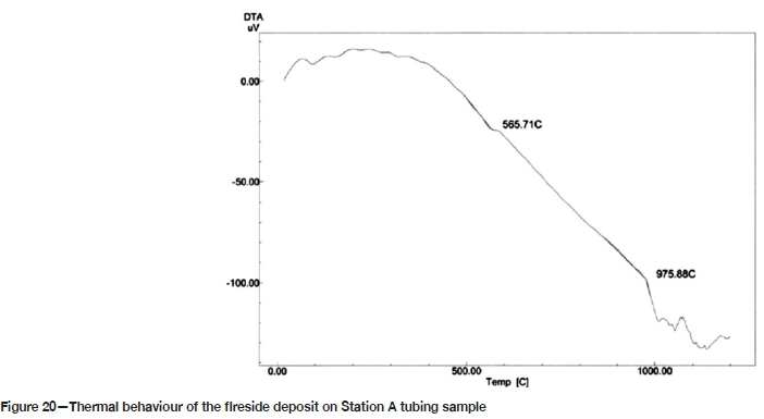
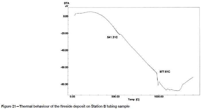
Differential thermal analysis (DTA)
DTA results for stations A and B revealed similar thermal behaviour. Peaks were generally measured at temperatures from 950 to 1250°C. On isolated samples from stations A and B, lower temperature activities were indicated at 565°C and 541°C respectively, as shown in Figures 20 and 21. These thermal activities seem to correlate with a survey reported by Bryers (1995) on the thermal behaviour of minerals commonly found in coal. Bryers showed that kaolinite transforms into metakaolinite at temperatures around 500°C, which further transforms into other forms of aluminosilicate at around 925°C and 1100°C. At lower temperatures pyrite (FeS2) oxidizes to form FeO and Fe sulphide, which occurs at 475°C. FeO transforms further into Fe2O3 at 525°C. The low-temperature peaks (at 541 and 565°C) measured on Station A and B samples are likely an indication of the oxidation of pyrite to FeS and Fe2O3, whereas the thermal peaks measured above 900°C may represent metakaolinite transformation into other forms of aluminosilicate such as mullite.
Discussion
The systematic investigation and characterization of the fireside deposits on the furnace wall boiler tubes from the three coal-fired power stations yielded unambiguous results that indicate the same mechanism of fireside corrosion. SEM-EDS and QEMSCAN analyses revealed that the fireside scale was composed of three distinct layers with a Fe-oxide and Fe-sulphide rich inner layer, a Fe-sulphide rich middle layer, and the outer layer consisting of low Fe-sulphide, high Fe-oxide, and low to moderate levels of fly ash particles. The iron oxide was mainly in the form of Fe3O4 and Fe2O3 and the iron sulphide was identified as predominantly pyrrhotite (FeS), with low levels of galena (PbS) and pyrite (FeS2). Fly ash particles consisted mostly of silica (SiO2) and aluminosilicate associated with calcium and magnesium. The thermal phase transformations of aluminosilicate, i.e. metakaolinite, into mullite, were detected consistently at temperatures in the range 950-1250°C, which concurs with thermal behaviour described by Bryers (1995). Lower temperature peaks were measured between 500 and 600°C, indicating pyrite (FeS2) transformation to FeS, Fe2(SO4)2, and FeO (Corey, 1964). The coexistence of high levels of pyrrhotite with iron oxide and the presence of pyrite in the fireside deposit is indicative of reducing conditions in the furnace as well as on the surface of the boiler tubes.
The morphology and characteristics of the fireside deposits from stations A, B, and C contradict the theory presented by Reid, Corey, and Cross (1945) and Srivastava, Godiwalla, Banerjee (1997), who identified the pyrosulphates, molten at temperatures exceeding 398°C for sodium pyrosulphate (Na2S2O7) and 454°C for potassium pyrosulphate (K2S2O7), as being responsible for fireside corrosion of boiler tubes. Neither sodium nor potassium were detected in the fireside deposits from stations A, B, and C. Instead, a phase rich in iron sulphide was identified consistently. French (1982) and Yu etal. (2017), in several failure investigations of furnace wall tubes, consistently detected sulphur, oxygen, iron, silicon, and chromium in the ash deposits, and also identified this type of fireside corrosion mechanism. No sodium, potassium, or chlorine were detected in these studies. French (1982) suggests that corrosion attack on the furnace wall tubes is associated with sulphides and requires strongly reducing conditions at the tube surface. He further states that carbon is required to stabilize the sulphites that form; carbon can enter the ash deposit either as unburned char or by deposition from carbon monoxide. Yu et al. (2017) found that the corrosion products were composed mostly of iron-containing sulphide and magnetite, and as a result classified the corrosion in that power plant as the sulphide corrosion. They further state that high-temperature corrosion of the sulphide type is due mainly to the large amounts of H2S, detached sulphur, and unstable FeS that would be formed in the oxygen-deficient conditions when a high-sulphur coal is burned.
Reducing conditions occur when there is limited excess oxygen (< 2%) in the furnace. Bakker (1998) states that low excess O2 favours the gasification process over combustion. Gasification results in the formation of H2S and limits oxidation of CO and combustion of pyrite (FeS2). This occurs through the reaction of sulphur in the coal (FeS2, S(org)) and some H2 present in the flue gas, which can be partially converted into H2S instead of SO2 (Davis et al., 2001; Chou, 1984-1986) through the following reactions:
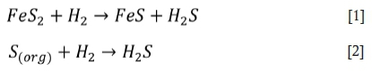
Reid, Corey, and Cross (1945) observed that under highly reducing conditions the pyrite is not completely burnt and the unburned pyrite is transported to the tube surface through flame impingement and may react directly with the iron in the tube walls, resulting in sulphidation:

The high amounts of CO and H2S favour a shift in the chemical equilibria for the sulphur species in the flue gas towards higher sulphur potentials and thus allow sulphidation of the metal to take place as well as oxidation (Bakker, 1998). When H2S is present in the flue gas, it will preferentially react with iron in the furnace wall tubes, through molecular diffusion, to form pyrrhotite (FeS):

By solid-state diffusion, already-formed Fe3O4 may also be transformed to FeS:

The substoichiometric conditions in the furnace were confirmed by the morphology and characteristics of the fireside deposits found on tubings from station A, B, and C, with the inner layer consisting of Fe3O4, Fe2O3, and FeS, the middle layer rich in FeS, and the outer layer rich in iron oxide, fly ash, and unburnt coal.
Davis et al. (2001) found that when the furnace of a pulverized coal boiler is operating under oxidizing conditions, corrosion rates will be negligible and the tube life will exceed the expected life. These conditions enable the formation of dense, adherent and protective mixed oxide/sulphide deposits leading to parabolic rate constants, as described in Equation [6], and are dependent only on metal temperature, with no effect of coal composition or heat flux.

where
KPo is the parabolic rate constant (cm2-s-1) under oxidation
A is a constant
Qo is the activation energy for oxidation (J-mole1)
R is the gas constant (8.3143 J/K-1-mole-1)
T is temperature (K).
When the furnace operates under reducing conditions (O2 < 0.5%, CO > 2%) in the absence of chlorine (Cl < 0.05%), the corrosion mechanism shifts progressively from oxidation towards sulphidation as the CO content of the flue gas increases and the O2 content declines. Increasing the CO content of the flue gas increases the corrosion rates via the formation of progressively more sulphide within the deposit as described in Equation [7].

where
Kpfis the parabolic rate constant (citf-sec1) under reducing conditions
B is a constant
Qris the activation energy for mixed oxidation sulphidation (J-mole-1)
%CO is the percentage of CO in the local combustion environment.
Gas analysis at unit 1 of Station A correlates with the findings by Davis et al. (2001). High levels of CO were measured at the furnace wall (up to 38 000 ppm) and furnace exit (> 3500 ppm) (Moodley, 2010, and van Wyk, 2010), which are areas with high wall thinning due to fireside corrosion. High CO concentrations are indicative of limited combustion caused by low excess O2. These conditions promote the formation of FeS-rich deposits as seen in unit 1 of Station A. Sulphide deposits allow higher rates of transport (diffusion) of iron cations than oxides, and the strength and adherence of the deposit decrease with increasing FeS content while its growth rate and permeability increase significantly. These deposits are also brittle and poorly adherent, so they readily crack, spall, and are easily removed by soot blowing or thermal cycling. The result is increased metal loss, which becomes the dominant factor in tube life. The morphology and characteristics of the fireside deposits on tubes from the three power stations are indicative of a sulphidation mechanism of fireside corrosion caused by reducing conditions in the furnace.
Conclusions
This investigation was aimed at gaining a better understanding of the mechanism(s) under which fireside corrosion is taking place on furnace wall tubes in Eskom's coal-fired boilers, and the role that the combustion process has played in promoting this fireside corrosion mechanism. The knowledge and understanding acquired from this study will not only be beneficial to the conventional subcritical coal-fired boilers, but also to subcritical boilers operated with low-NOx burners as well as supercritical boilers.
The conclusions drawn from the tests and analyses are as follows.
1. The mechanism of fireside corrosion taking place on the furnace walls in boilers at power stations A, B, and C is sulphidation due to FeS deposition. The main contributors to FeS deposition are reducing conditions in the furnace caused by high CO (> 2000 ppm) and low excess O2 (< 2%) in the flue gas and on the tube surface.
2. Sulphide scales allow higher rates of transport of iron cations than oxides, and they are brittle and poorly adherent so they readily crack and spall. The result is increased tube wall thinning, which becomes the dominant factor in tube life.
3. Sulphidation corrosion can be mitigated through effective combustion, which can be achieved by controlling the amount of free oxygen in the flue gas, within acceptable limits, > 2%, minimizing the amount of CO in the flue gas to below 2000 ppm, avoiding flame impingement on the tubes, and ensuring the use of the correct coal particle size to reduce the amount of unburned coal in the ash deposits.
4. The degree and extent of fireside corrosion is likely to increase in boilers operating with low-NOx combustion techniques and those operating at supercritical conditions. It is in these types of boilers where effective combustion process is highly necessary.
Acknowledgements
The author gratefully appreciates the support of Eskom Research, Testing and Development management.
References
ASTM A106/A106M:18. 2018. Standard specification for seamless carbon steel pipe for high-temperature service. ASTM International, West Conshohocken, PA. [ Links ]
ASTM A370. 2013. Standard test methods and definitions for mechanical testing of steel products/ ASTM International, West Conshohocken, PA. pp. 12-13. [ Links ]
Bakker, W. 1998. Waterwall wastage in low NOx boilers: Root causes and remedies. Report TR11155. Electric Power Research Institute, Charlotte, NC. [ Links ]
Bryers, R.W. 1995. Fireside slagging, fouling, and high-temperature corrosion of heat-transfer surface due to impurities in steam-raising fuels. Progress in Energy & Combustion Science, vol. 22. pp. 29-120. [ Links ]
BS EN 10216-2. 2013. Seamless steel tubes for pressure purposes - Technical delivery conditions, Part 2: Non-alloy and alloy steel tubes with specified elevated temperature properties, BSI Standard Publications, London. [ Links ]
Chabüla, N.D. 2009. Metallurgical analysis of failed boiler tubes. Eskom Generation Procedure GPC 36-5. Sandton, South Africa. pp. 5-6. [ Links ]
Chou, CL. 1984-1986. Distribution of sodium, chlorine, and sulphur in Illinois coals removal by cleaning and their behaviour during combustion. Final Technical Report. Illinois State Geological Survey. [ Links ]
Corey, R.W. 1964. Measurements and significance of the flow properties of coal ash slag. Bulletin 618. US Bureau of Mines. [ Links ]
Davis, C.J., James, P.J., Pinder, L.W., and Mehta, A.K. 2001. Effects of fuel composition and combustion parameters on furnace wall fireside corrosion in pulverised coal-fired boilers. Materials Science Forum,, vol. 369-372. pp. 857-864. [ Links ]
Dooley, R.B. and McNaughton, W.p. 2007. Boiler and heat recovery steam generator tube failures: Theory and practice. Vol. 2. Manual 1012757. Electric Power Research Institure, Charlotte, NC. [ Links ]
French, D.N. 1982. Furnace wall corrosion problems in coal fired boilers, corporate quality assurance. Proceedings of the National Association of Corrosion Engineers Conference, Houston, TX, 22-26 March. https://www.babcockpower.com/wp-content/uploads/2018/02/furnace-wall-corrosion-problems-in-coal-fired-boilers.pdf [ Links ]
Harb, J.N. and Smith, E.E. 1990. Fireside corrosion in PC-fired boilers. Progress in Energy and Combustion Science, vol. 16. pp. 169-190. [ Links ]
Hatt, R.M. 1990. Fireside deposits in coal-fired utility boilers, Island Creek Corporation. Progress in Energy and Combustion Science, vol. 16. pp. 235-241. [ Links ]
Moodley, L. 2010. Station A Unit 1 suction pyrometry tests economiser outlet measurements, revision 6. Research, Testing and Development, Eskom, Sandton, South Africa. [ Links ]
Reid, W.T. 1984. The relation of mineral composition to slagging, fouling and erosion during and after combustion. Progress in Energy and Combustion Science, vol. 10. doi:10.1016/0360-1285(84)90100-X [ Links ]
Reid, W.T., Corey, R.C., and Cross, B.J. 1945. External corrosion of furnace-wall tubes - I History and occurrence. Transactions of the ASME, vol. 67. pp. 279-285. [ Links ]
Srivastava, S.C., Godiwalla, K.M., and Banerjee, M.K. 1997. Fuel ash corrosion of boiler and superheater tubes. Journal of Materials Science (UK), vol. 32, no. 4. pp. 835-849. [ Links ]
Syed, A., Simms, N., and Oakey, J. 2011. Fireside corrosion study of superheater materials in advanced power plants. School of Applied Science, Cranfield University. http://dspace.lib.cranfield.ac.uk/handle/1826/7181 [ Links ]
Van Wyk, D.C. 2010. Station A preliminary report: Gas analysis test on Unit 1. Generation Business Unit, Eskom, Sandton, South Africa. [ Links ]
Yu, X., Gong, B., Gao, Q., Zhao, Y., Tian, C., and Zhang, J. 2017. Investigation of fireside corrosion at water-cooled wall from a coal-fired power plant in China. China Electric Power Research Institute. [ Links ] ♦
 Correspondence:
J.W. Van der Merwe
Email: josias.vandermerwe@wits.ac.za
Received: 2 Oct. 2019
Revised: 18 Mar. 2021
Accepted: 30 Mar. 2021
Published: June 2021
ORCID
J.W. Van der Merwe https://orchid.org/0000-0003-4563-8078

