


Services on Demand
Article
 English (pdf)
 Article in xml format
 Article references
Indicators

Related links
-
 Cited by Google
 -
 Similars in Google
Share

 Permalink
Journal of the Southern African Institute of Mining and Metallurgy
On-line version ISSN 2411-9717
Print version ISSN 2225-6253
J. S. Afr. Inst. Min. Metall. vol.121 n.4 Johannesburg Apr. 2021
http://dx.doi.org/10.17159/2411-9717/1340/2021
ARTICLES
The crack growth resistance behaviour of aluminium alloy 2024-T3 at slow strain rates after exposure to standard corrosive environments
C.C. Pretorius; R.J. Mostert; S. Ramjee
Department of Materials Science and Metallurgical Engineering, University of Pretoria, South Africa
SYNOPSIS
The study investigates the effect of prior corrosive exposure on crack growth resistance behaviour of thin sheet (3 mm thick) aluminium alloy 2024-T3 at slow strain rates. Compact tension specimens were exposed to standard corrosive environments that simulate accelerated atmospheric corrosion attack. TWo corrosive environments were considered - an exfoliation corrosion (EXCO) solution and a 3.5 wt% sodium chloride solution. The unloading compliance R-curves of the two-hour EXCO-exposed specimens revealed a significant degradation of approximately 11% in the crack growth resistance behaviour (Kcevalues) compared to the baseline (air-exposed) values. Furthermore, secondary intergranular crack formation was also revealed in the plastic zone ahead of, and adjacent to, the crack tip of these specimens; which formed during the crack growth resistance loading. It is postulated that the observed degradation of the Kce values of the EXCO-exposed material is due to hydrogen embrittlement since the exposure times for the EXCO evaluation were limited to ensure that uniform corrosion dominated; that is, significant penetration of corrosion damage and pitting due to localized corrosive attack did not occur. The sodium chloride-exposed specimens revealed a similar degradation (13%) after 24 hours exposure. However, slight intergranular corrosive attack and isolated pitting were observed on the exposed surfaces prior to crack growth resistance loading, resulting in notch effects that could assist in crack growth. Pitting and intergranular corrosion were, however, not observed at the pre-crack tip. The relative contributions of the notch effects and the hydrogen embrittlement during the degradation of the KR performance are, therefore, unclear.
Keywords: corrosion, crack growth, aluminium alloy 2024-T3.
Introduction
The long-term service usage of the popular high-strength aluminium alloy 2024 in the aeronautical industry may lead to degradation in the alloy's mechanical properties due to atmospheric corrosion exposure. Various authors have described a decrease in the strength and ductility of the alloy during its service life (Alexopoulos et. al, 2012, 2016; Kamoutsi et. al., 2006; Sharp et. al., 1998; Sharp, Mills, and Clark, 2001). In the aeronautical industry, this degradation may be brought on by a number of embrittlement mechanisms; including the natural ageing of the alloys, exfoliation corrosion, and hydrogen embrittlement (Alexopoulos et. al, 2016).
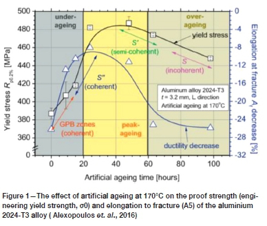
The well-established natural ageing of the alloy is a result of the growth and coarsening of the strengthening precipitates over time at ambient temperatures. Growth of the strengthening precipitates ultimately leads to a loss of coherency with the aluminium matrix; which is accompanied by the loss of the so-called coherency strains that hinder dislocation glide and provide strengthening. This may be followed by coarsening - in which the larger precipitates grow at the expense of the smaller ones (Ratke and Voorhees, 2002) - which will reduce the inter-precipitate spacing and aid in dislocation glide due to fewer obstacles hindering dislocation mobility. Moreover, owing to the general incoherency of the larger precipitates, dislocations can no longer intersect the precipitates. Accordingly, dislocations have to loop around the precipitates for dislocation motion to persist. In so doing, dislocation loops are formed around the precipitates, which act as dislocation sources that ultimately decrease the ductility of the alloy. It has been well established that the ultimate strengthening is brought on by the coherent and semi-coherent precipitates; due to the aforementioned coherency strains and relatively high precipitate density per unit area that accompany such precipitates. With the growth and coarsening of the precipitates (and ultimate incoherency), a lower mechanical strength and ductility often results. More specifically, this has a drastic effect on the proof strength (or yield strength) and the final elongation to failure; as can be seen in Figure 1 for aluminium alloy 2024-T3 artificially aged at 170°C at various ageing times (Alexopoulos et. al., 2016).
Atmospheric corrosion of aluminium alloy 2024-T3 in the aeronautical industry is widely relevant due to the structural components manufactured from the alloy being regularly exposed to moisture and other corrosive environments during their service lives. With regard to the aeronautical industry, the most common manifestations of atmospheric corrosion include pitting and exfoliation. Kamoutsi et. al., (2006) showed that atmospheric corrosion of the aluminium alloy 2024-T3 is initiated by a localized breakdown of the protective surface oxide layer, which is then followed by localized corrosion (in the form of pitting) before corrosion proceeds. Similarly, Alexopoulos et al., (2012) investigated the effect of corrosion exposure time for ultra-thin sheet aluminium alloy 2024-T3, which showed similar results. The authors also showed that intergranular corrosion proceeds after the corrosion pit reaches a critical size, and grows laterally (perpendicular to the corrosion pits and parallel to the surface) in a direction parallel to the rolling direction (Alexopoulos et al., 2012).
The ASTM G34-1 standard (ASTM International, 2018) defines exfoliation as corrosion that proceeds laterally along planes parallel to the surface (generally along grain boundaries), where it forms corrosion products that force the matrix apart. The standard also provides guidance for producing this degradation in an accelerated manner. Specifically pertaining to 2XXX and 7XXX aluminium alloys, the Exfoliation Corrosion (EXCO) solution was developed to simulate accelerated exfoliation corrosion attack, and is said to provide a useful prediction of the exfoliation corrosion when exposed to marine atmospheres (ASTM International, 2018). Exposure to such corrosive environments ultimately gives rise to a layered surface appearance (ASTM International, 2018), as shown in the work by Sharp, Mills, and Clark (2001) on aluminium alloy 7075-T651 after exposure to the EXCO solution for 48 hours (refer to Figure 2).
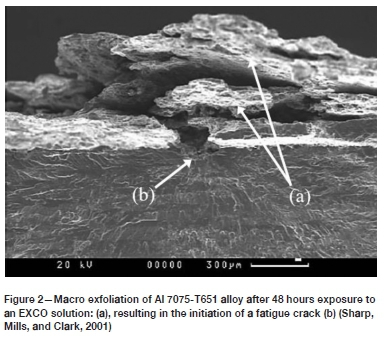
The presence of such an exfoliated surface layer will, of course, affect the mechanical properties in a deleterious way. Various authors have described a loss in both strength and ductility with increasing corrosion exposure time (Alexopoulos et. al., 2012, 2016; Kamoutsi et.al., 2006; Sharp et. al., 1998; Sharp, Mills, and Clark, 2001). Furthermore, as a result of localized stress concentrations (notch effects) at the exfoliated surface, the probability that the corrosion will interact with other damage mechanisms also increases with the extent of exfoliation (Kamoutsi et. al., 2006). An example of such interaction may be seen by referring again to the work by Sharp, Mills, and Clark (2001), which shows that the exfoliated surface resulted in the initiation of a fatigue crack in aluminium alloy 7075-T651 (Figure 2).
A number of mechanical testing investigations of pre-corroded aluminium alloy 2024 have shown that the deleterious effects on the strength and ductility of these alloys are directly related to the corrosion exposure time (Dovletoglou et. al., 2018; Pantelakis, Daglaris, and Apostolopoulos, 2000; Petroyiannis et. al., 2004). However, these experiments also showed that, although the residual strength of the alloy can be recovered after removal of the corrosion layer, the ductility cannot (Dovletoglou et. al., 2018; Kamoutsi et. al., 2006; Pantelakis, Daglaris, and Apostolopoulos, 2000; Petroyiannis et. al., 2004). Furthermore, the studies also showed that moderate heating of the alloy after removing the corroded surface layer assists in the partial recovery of the ductility. This has been proposed as experimental evidence that the degradation of the ductility of aluminium alloy 2024 during corrosive attack is accompanied by a corrosion-induced mechanism of hydrogen embrittlement (Kamoutsi et. al., 2006). It was proposed that atomic hydrogen is introduced to the alloy during the atmospheric corrosion process through the reduction of water according to Equation [1], followed by adsorption of the hydrogen atoms on the surface (Azofeifa et. al., 1997).
The atomic hydrogen may then either be absorbed into the aluminium matrix, or react on the surface to form hydrogen gas (H2). In the former case, the atomic hydrogen will diffuse to certain preferred lattice sites such as grain boundaries, line defects, matrix/precipitate interfaces, and point defects; which act as hydrogen traps (Charitidou et. al., 1999). The presence of the hydrogen at these sites may result in embrittlement of the alloys through one, or a combination, of the conventional hydrogen-embrittlement mechanisms (Charitidou et. al., 1999). These are (i) the hydrogen-enhanced decohesion embrittlement mechanism (HEDE), (ii) the hydrogen-enhanced localized plasticity (HELP) mechanism, (iii) the adsorption-induced dislocation emission (AIDE) mechanism, and (iv) hydride formation and fracture (Birnbaum, 1990; Birnbaum et. al., 1997; Lynch, 2011; Milne, Rictchie, and Karihaloo, 2003; Troiano, 1974).
Although the details of these mechanisms will not be discussed here, it is important to note that they have one aspect in common; that is, hydrogen accumulates at regions of triaxial stress (or strain). In recent work by Alexopoulos et al. (2016), slow strain rate tensile tests were performed on the aluminium alloy 2024-T3 after short-term exposure to an EXCO solution. The investigation showed that the degree of embrittlement correlates with the size, location, and number of S-type (Al2CuMg) precipitates. This may provide an understanding of the role played by the triaxial elastic strains that accompany the coherent and semi-coherent precipitates during the hydrogen-embrittlement process. It is obvious that a number of negative implications arise from the fact that the alloy suffers from such embrittling effects; especially considering that this may occur under atmospheric conditions.
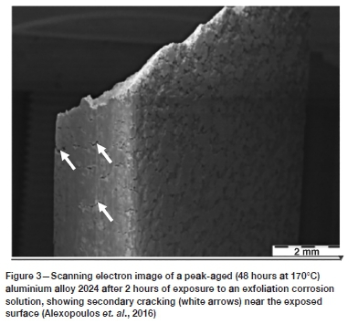
Examination of certain photographs in the published work by Alexopoulos et al. (2016) led to the impression that the application of plastic strain to EXCO-embrittled tensile specimens after short-term exposure resulted in the formation of numerous surface cracks prior to the fracture of the specimens (Figure 3). The initiation of such surface cracks at relatively low strains, or alternatively, in the vicinity of stress concentrations (such as a notch or a fatigue crack), poses a significant risk to the structural integrity of components constructed from these alloys. This is especially true in the aeronautical industry, in which some aluminium-based structures are exposed to marine atmospheres for significant durations. In the current work, this effect is investigated using advanced analytical techniques such as X-ray microcomputed tomography (MicroCT). Furthermore, the assumed effect of EXCO-induced hydrogen embrittlement on the crack growth resistance behaviour of the alloy has not been studied extensively. The present work is, therefore, concerned with the ability of thin sheet (3.16 mm thickness) aluminium alloy 2024-T3 to resist the extension of a pre-existing (fatigue-induced) crack after being exposed to an environment that provides the necessary conditions for hydrogen embrittlement and/or corrosion.
Material and specimen preparation
The compact tension specimens used for the crack growth resistance (KR) evaluation were machined from 3.2 mm thick plate material of aluminium alloy 2024-T3. As such, various specimen preparation steps were required prior to the crack growth resistance evaluation, which included the machining and fatigue pre-cracking of specimens, as well as prior exposure to the different environments considered. Preparation of the relevant exposure environments was also required prior to the mechanical testing. The following sections provide a brief description of all the preparation steps prior to crack growth resistance evaluation.
Preparation of exposure environments
The KR specimens were pre-exposed to three environments: (i) air for the baseline KR values, (ii) a 3.5% sodium chloride solution, and (iii) an EXCO solution. A brief description of the preparation methodology and relevant ASTM standards for the latter two exposure environments is given.
Sodium chloride solution
The 3.5% sodium chloride solution was prepared in accordance with the ASTM G44-99(2013) standard (ASTM International, 2013). After buffering with hydrochloric acid, the solution pH was measured at 6.5.
EXCO solution
The Exfoliation Corrosion exposure environment is a solution comprising approximately 4.0 M sodium chloride (NaCl), 0.5 M potassium nitrate (KNO3), and 0.1 M nitric acid (HNO3). The solution was prepared in accordance with section 7 of the ASTM G34-01 standard (ASTM International, 2018). The pH of the solution was measured at 0.27.
Crack growth resistance specimen preparation
Machining and fatigue precracking.
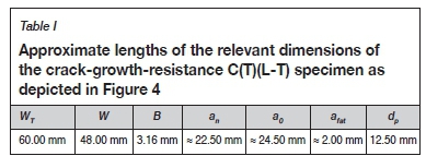
Machining commenced with the sectioning of blank squares (60 mm χ 60 mm) from the 3.2 mm thick plate material of aluminium alloy 2024-T3, providing the basis for compact tension (C(T)) specimens as prescribed in section 8.3 of the ASTM E561-15a standard (ASTM International, 2019). The blank specimens were then notched to produce C(T)(L-T) type crack growth resistance test specimens, with a fatigue starter notch (radius 0.12 mm) in accordance with the ASTM E561-15a standard. The specimens were further processed by the mechanical testing laboratory at CSIR to introduce the required fatigue pre-cracks using an Instron 1342 servo-hydraulic testing machine operating on Instron crack propagation software. The specimen geometry and relevant specimen dimensions are shown in Table I and Figure 4.
KR specimen preparation prior to environmental exposure
Further specimen preparation was required prior to the exposure of the specimens to the different environments. The preparation consisted of shielding the most of the specimen surface area from the corrosive, ensuring that only a 10 mm wide section near the specimen notch/precrack configuration would be exposed. This was achieved by initially covering the relevant areas with a layer of double-sided tape, followed by a double layer of adherent PVC tape. It should also be noted that the relevant specimen dimensions for the crack growth-resistance evaluation (i.e. W, B, and an) were measured prior to the shielding and exposure procedures.
The sodium chloride exposure procedure
After the shielding of the nessasary specimen surface areas, 100 ml of the sodium chloride solution was added to a container capable of holding the 60 mm χ 60 mm C(T) specimen whilst ensuring full coverage of the relevant surfaces. The volume of 100 ml provides the required minimum volume to exposed surface area ratio of 10 ml/cm2 as prescribed in section 11 of the ASTM G34-01 standard (ASTM International, 2018). The specimen was then placed in the container, and exposed to the soluton for 24 hours at room temperature. After exposure, the specimen was removed from the container and the exposed surface was lightly cleaned with acetone before removing the shielding and performing the KR evaluation.
The EXCO solution exposure procedure
The exposure of the specimens to the EXCO solution was performed in a similar manner as for the sodium chloride solution; the only difference being a decrease in the exposure time to 2 hours.
Experimental procedure
Crack growth resistance evaluation
The crack growth resistance evaluations for all the relavent exposure conditions were performed using an MTS Criterion Series 45 static test system operating on MTS Elite Test Suite software. As per the unloading compliance method of the ASTM E561-15a standard (ASTM International, 2019), the software was specially programmed to introduce a number of unloading/reloading sequences during each test under crosshead extension control. Furthermore, the grips and fixtures prescribed in ASTM E1820 were used to install the C(T)(L-R) specimen onto the testing system's loading axis. Additional steps were included during installation and testing so as to ensure maximum reproducibility in the test results. These are (i) ensuring good and similar alignment of the test specimens with the test system's loading axis (achieved through the use of spacers during specimen installation), (ii) the application of a small (0.2 kN) preload prior to installation of the crack mouth opening displacement (CMOD) gauge, and (iii) the use of the same reference specimen for the CMOD gauge zero value. The KR testing then commenced with a crosshead extension rate of 0.03 mm-min-1 until a crack mouth opening displacement of 3.0 mm was achieved, along with a total of 21 equally spaced (w.r.t. displacement) unload/reload sequences. Thereafter, the specimens were subjected to a final loading at a significantly higher crosshead extension rate (300 mm-min-1) until complete separation. The stable crack extension was then measured using a stereo microscope, and taken as the average of nine measurements over the thickness of the specimen.
Scanning electron fractography
Scanning electron fractography was performed using a Joel JSM IT300 scanning electron microscope (15 kV) in order to compare the fracture surface appearances under the different exposure conditions.
Microcomputed tomography
The KR test procedure for the specimens sent for X-ray MicroCT was interrupted prior to final fracture and separation. After the KR test terminated at a 3 mm CMOD reading, the specimens were sent for EDM in order to produce a smaller specimen that contained the notch/crack configuration. The specimens were then subjected to MicroCT scanning at the University of Stellenbosch.
Results and discussion
Baseline crack growth resistance results
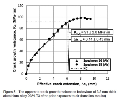
The baseline (air-exposed) crack growth resistance curves are shown in Figure 5. In accordance with the compliance method prescribed in the ASTM E561-15a standard, an average apparent resistance to crack extension (KCe) of 91 ± 2.8 MPaVm was obtained at an effective crack extension (Aae) of 6.14 ± 0.43 mm. This value is significantly higher than that reported (61.6 ± 8.0 MPaVm) by Reynolds (1996). The deviation is believed to be due to (i) the low displacement rate used in the current investigation, and (ii) the reduced size of the remaining ligament of material - both of which will alter the degree of plasticity ahead of the crack front. With regard to the former, owing to the low displacement rate, the initial rate of change in stress intensity does not fall within the limits of 0.55-2.75 MPaVm-s-1 (as set out by the ASTM E561-15a standard). The reduced impact of the loading rate increases the probability for crack tip blunting, since a larger fraction of the material (ahead of the crack) may absorb the applied energy through plastic yielding. The reduced size of the remaining ligament of material will have a similar effect on C(T)-type specimens, with an increase in the plastic zone size and a larger fraction of material absorbing the applied energy. Consequently, the values determined in this study do not represent the plane-stress fracture toughness of alloy 2024-T3 at a thickness of 3.2 mm. It is for these reasons that the normal nomenclature, as given in the relevant ASTM standards, is not used to describe the crack growth resistance values. Nevertheless, due to the comparative nature of the investigation, the values may be used to establish whether the exposure environments alter the crack growth response of the alloy. In this respect, the increase in plasticity in point of fact benefits the investigation, since embrittling effects should alter the plastic response through either the hindrance or localization of plastic flow.
Environmentally exposed crack growth resistance results
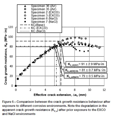
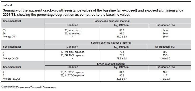
The KR curves for the environmentally exposed and baseline results are compared in Figure 6. A significant degradation may be seen in the crack growth-response of both the sodium chloride- and EXCO-exposed materials. With regard to the former, a reduction in the apparent crack growth resistance (KCe) of approximately 13.0 ± 0.5% is observed, with a KCe of 79.0 ± 0.5 MPaVm. Similarly, the EXCO-exposed material revealed a reduction of approximately 11.2 ± 0.1% with a KCe of 81.0 ± 0.7 MPaVm. The degradation in the crack growth resistance behaviour is recorded in more detail in Table II.
Fracture surface appearance and MicroCT mapping:
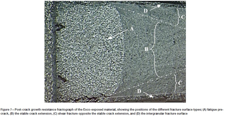
The fracture surface appearance of the EXCO-exposed material is shown in Figure 7. From this fractograph, it is clear that the fracture surface may be subdivided into four regions. That is, (A) the fatigue precrack perpendicular to the applied load, (B) the stable crack extension fracture surface (also perpendicular to the applied load), (C) the shear (ductile) type fracture surface with an orientation of approximately 45° to the applied load, and (D) an intergranular type fracture surface near the edge of the specimen.
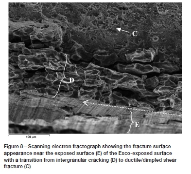
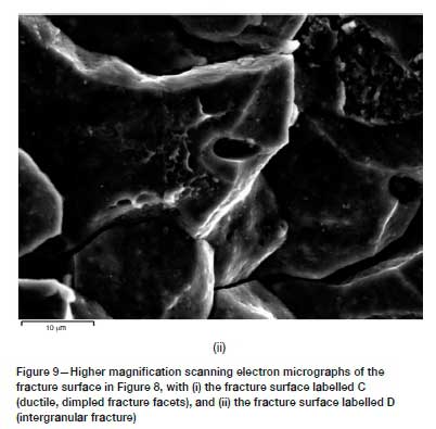
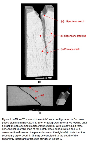
The fracture surface types (A) to (C) were found to repeat during all the exposure conditions investigated. However, only the EXCO-exposed specimens revealed the type (D) fracture surface appearance. The high-resolution scanning electron fractograph in Figure 8 shows the transition from intergranular (type D) to dimple fracture for the EXCO-exposed material in more detail, with Figure 9 showing higher magnification scanning electron fractographs of the fracture surfaces labelled C (Figure 9i) and D (Figure 9ii). It becomes apparent that significant weakening of the grain boundary strength has occurred during the two-hour exposure to the EXCO solution. It is also found that the intergranular fracture surfaces correlate well with the secondary crack formation (refer to the MicroCT scan in Figure 11) that resulted within the plastic zone of the material during crack growth resistance loading.

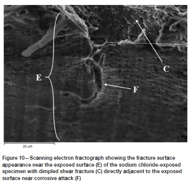
Optical microscopy of the EXCO-exposed surfaces prior to the KR loading revealed no evidence of substantial pitting and/or intergranular corrosion. Also, secondary intergranular cracking was not observed in the sodium chloride-exposed specimens, with a ductile (dimple-facet) type fracture surface directly adjacent to the exposed surface (refer to Figure 10). Additionally, microscopy of the sodium chloride-exposed alloy prior to KR loading revealed localized attack in the form of isolated pitting and intergranular corrosion on the exposed surfaces. It is thought that the variation in the localization of corrosive attack between the two exposure environments is a result of the difference in pH - that is, the significantly lower pH of the EXCO solution results in the rapid breakdown of the protective surface oxide layer, whereas only a localized breakdown of the oxide layer occurs at the more neutral pH of the sodium chloride solution. Consequently, uniform surface reactions may ensue in the case of the EXCO solution, while only localized (pitting) reactions are possible for the sodium chloride solution. Furthermore, it is probable that the low pH of the EXCO solution provides an abundance of hydrogen at the exposed surface, which may be absorbed via the grain boundaries of the alloy, thus embrittling the grain boundaries though one of the hydrogen embrittlement mechanisms mentioned in the Introduction. Further research is required to clarify if the intergranular fracture surface near the EXCO-exposed surface is in fact due to hydrogen embrittlement and, if so, which of the hydrogen embrittlement mechanisms induced the embrittlement; i.e. the HEDE, HELP, AIDE, or hydride formation mechanism. Other possible causes could be micro-corrosion at the grain boundaries or galvanic-type corrosion at the interfaces of the grain boundary intermetallic precipitates and the aluminium matrix.
With regard to the sodium chloride-exposed material, it is possible that the degradation in the crack growth response is adversely influenced by the localized stress concentrations that accompany the isolated pitting and areas of intergranular corrosion. The notch effects that arise from the presence of these surface defects would amplify the triaxial stress ahead of the crack front, which would aid in the extension of the crack. Nevertheless, the fact that the pits and grain boundary cracks were isolated and were not observed at the precrack tip highlights the probable contribution of hydrogen embrittlement.
Conclusions
Exposing aluminium alloy 2024-T3 sheet to a standard EXCO solution for a short duration (2 hours) resulted in no general corrosion. However, a number of embrittling effects were identified. During KR testing at slow strain rates, the KCe values were reduced by 11.2 ± 0.1% compared to the equivalent value prior to exposure. After interruption of the KR testing at a crack mouth opening displacement of 3 mm, many secondary cracks -parallel to the main crack front and on the exposed surface - were observed within the plastic zone. The fracture surface in this region was intergranular, while the fracture surface of the main crack front was ductile with a dimpled nature.
Exposure of the same alloy to a NaCl solution for 24 hours also led to a reduction of the KCe values during KR testing at slow strain rates. In this case, the reduction was found to be 13.0 ± 0.5%, and isolated intergranular etching and localized pitting were observed on the exposed surface.
Acknowledgements
The assistance of Nikos Alexopoulos and his team at the University of the Aegean in providing the blanks for the KR testing and for fruitful discussions is gratefully acknowledged. The MicroCT analyses were sperformed by Anton du Plessis of the 3D Innovation Research Group at Stellenbosch University. The assistance of Chris McDuling and Steven Masete from the Mechanical Testing Laboratory of the CSIR in performing the fatigue precracking of the KR samples is gratefully acknowledged. The work was financially supported by the Light Metals Development Network of the Department of Science and Innovation.
References
Alexopoulos, N., Dalaköüras, P., Skarvelis, P., and KouRKouLis, S. 2012. Accelerated corrosion exposure in ultra-thin sheets of 2024 aircraft aluminium alloy for GLARE applications. Corrosion Science, vol. 55. pp. 289-300. [ Links ]
Alexopoulos, N., Velonaki, Z., Stergiou, I., and Kourkoulis, S. 2016. The effect of artificial ageing heat treatments on the corrosion-induced hydrogen embrittlement of 2024 (Al-Cu) aluminium alloy. Corrosion Science, vol. 102. pp. 413-424. [ Links ]
ASTM international. 2013. ASTM G44-99(2013). Standard practice for exposure of metals and alloys by alternate immersion in neutral 3.5% sodium chloride solution. West Conshohocken, PA. [ Links ]
ASTM International. 2018. ASTM G34-01(2018). Standard test method for exfoliation corrosion susceptibility in 2XXX and 7XXX series aluminium alloys (EXCO Test). West Conshohocken, PA. [ Links ]
ASTM International. 2019. ASTM E561-19. Standard test method for KR curve determination. West Conshohocken, PA. [ Links ]
Azofeifa, D., Clark, N., Amador, A., and Saenz, A. 1997. Determination of hydrogen absorption in Pd coated Al thin films. Thin Solid Films, vol. 300. pp. 295-298. [ Links ]
Birnbaum, H. 1990. Mechanisms of hydrogen related fracture of metals. Hydrogen Effects on Materials Behaviour. [ Links ]
Moody, N. and Thompson, A. (eds). TMS, Warrendale, PA. pp. 639-658. [ Links ]
Birnbaum, H., Robertson, I., Sofronis, P., and Teter, D. 1997. Mechanisms of hydrogen related fracture - A review. Corrosion-Deformation Interactions. [ Links ]
Magnin, T. (ed.). Instutute of Materials, London. pp. 128-195. [ Links ]
Charitidou, E., Papapolymerou, G., Haidemenopoulos, G., Hasiotis, N., and Bontozoglou, v. 1999. Characterization of trapped hydrogen in exfoliation corroded aluminum alloy 2024. Scripta Materialia, vol. 41. pp. 1327-1332. [ Links ]
Dovletoglou, E., Skarvelis, P., Stergiou, v., and Alexopoulos, N. 2018. Effect of corrosion exposure on the mechanical performance of 2024 aluminum alloy electron beam welded joints. Procedia Structural Integrity, vol. 10. pp. 73-78. [ Links ]
Kamoutsi, H., Haidemenopoulos, G., Bontozoglou, v., and Pantelakis, S. 2006. Corrosion-induced hydrogen embrittlement in aluminum alloy 2024. Corrosion Science, vol. 48. pp. 1209-1224. [ Links ]
Lynch, S. 2011. Hydrogen embrittlement (HE) phenomena and mechanisms. Stress Corrosion Cracking. Raja, V. and Shoji, T. (eds). Woodhead Publishing, Sawston, Cambridge, UK. pp. 90-130. [ Links ]
Milne, I., Ritchie, R., and Karihaloo, B. 2003. Hydrogen assisted damage mechanisms. Comprehensive Structural Integrity. Elsevier. pp. 69-74. [ Links ]
Pantelakis, G., Daglaras, P., and Apostolopoulos, C. 2000. Tensile and energy density properties of 2024, 6013, 8090 and 2091 aircraft aluminum alloy after corrosion exposure. Theoretical and Applied Fracture Mechanics, vol. 33. pp. 117-134. [ Links ]
Petroyiannis, P., Kermanidis, A., Papanikos, P., and Pantelakis, S. 2004. Corrosion-induced hydrogen embrittlement of 2024 and 6013 aluminum alloys. Theoretical and Applied Fracture Mechanics, vol. 41. pp. 173-183. [ Links ]
Ratke L. and voorhees, P. 2002. Nucleation, growth and coarsening. Growth and Coarsening. Engineering Materials. Springer, Berlin, Heidelberg. https://doi.org/10.1007/978-3-662-04884-9_10 [ Links ]
Reynolds, A. 1996. Comparison of R-Curve methodologies for ranking the toughness of aluminium alloys. Journal of Testing and Evaluation, vol. 24. pp. 406-410. [ Links ]
Sharp, P., Cole, G, Ciark, G., and Russo, G. 1998. The influence of corrosion on aircraft structural integrity. Proceedings of the 21st Congress of the International Council of the Aeronautical Sciences, ICAS 98, Melbourne, Victoria, 13-18 September. https://www.researchgate.net/publication/281061282_The_Influence_of_Corrosion_on_Aircraft_Structural_Integrity [ Links ]
Sharp, P., Mills, T., and Clark, G. 2001. Aircraft structural integrity -The impact of corrosion. https://citeseerx.ist.psu.edu/viewdoc/download?doi=10.1.1.880.1779&rep=rep1&type=pdf [ Links ]
Troiano, A. 1974. Hydrogen in Metals. Bernstein, I. and Thompson, A. (eds). ASM International, Materials Park, OH. pp. 3-15. [ Links ]
 Correspondence:
C.C. Pretorius
Email: ccep@live.co.za
Received: 31 Aug. 2020
Revised: 25 Feb. 2021
Accepted: 13 Mar. 2021
Published: April 2021
ORCID: C.C. Pretorius https://orchid.org/0000-0002-8408-8390; R.J. Mostert https://orchid.org/0000-0002-8592-1313; S. Ramjee https://orchid.org/0000-0003-0104-207x

