


Services on Demand
Article
 English (pdf)
 Article in xml format
 Article references
Indicators

Related links
-
 Cited by Google
 -
 Similars in Google
Share

 Permalink
Journal of the Southern African Institute of Mining and Metallurgy
On-line version ISSN 2411-9717
Print version ISSN 2225-6253
J. S. Afr. Inst. Min. Metall. vol.121 n.2 Johannesburg Feb. 2021
http://dx.doi.org/10.17159/2411-9717/1140/2021
MINE HEALTH AND SAFETY PAPERS
Accretion formation on the refractory lining during the melting of ferrosilicon
T.M. NemavholaI, II; T. CoetseeI; A.M. Garbers-CraigI
IDepartment of Materials Science and Metallurgical Engineering, University of Pretoria, Pretoria, South Africa
IIExxaro FerroAlloys, Pretoria West, South Africa
SYNOPSIS
Accretions often form in furnaces when slag and charge materials attach to the refractory wall and build up over time. Accretion formation is usually unwanted because it reduces the working volume of the reactor and hinders material flow through the reactor. However, in some instances a thin, stable accretion layer may be desirable to protect the underlying refractory material. In order to prevent and/or manage accretion formation, it is important to understand the underlying principles of this phenomenon in the particular reactor.
Excessive accretion formation hampered production at the Exxaro FerroAlloys ferrosilicon melting and atomization plant. This plant uses induction furnaces in which a 15% silicon-iron alloy is produced by batch smelting a mixture of ferrosilicon of 75%Si grade and low-carbon steel. The molten ferrosilicon alloy is then gas-atomized to a powdered product for use as a dense medium in mineral processing plants. The objective of this study was to investigate the effect of different impurity levels in the ferrosilicon feed material on the extent of accretion formation as well as the effect on the accretion properties, which influence the ease of accretion removal upon furnace shut-down. Refractory and accretion samples were collected after a furnace shut-down and characterized using X-ray diffraction and scanning electron microscopy-energy dispersive spectroscopy. It was concluded that the trace elements in the FeSi-75 feed material (Al, Ca, Mn) were mostly responsible for accretion formation, but that rust on the low-carbon steel and oxidation of the steel contributed to accretion attachment to the lining. The total contaminant content, calcium to aluminium ratio in the FeSi-75 feed material, and thereby the liquid to solids ratio in the accretion at temperature determine the strength of attachment as well as growth of the accretion.
Keywords: Accretion, build-up, slag, refractory lining, ferrosilicon.
Introduction
Atomized ferrosilicon is produced by melting high-grade crude FeSi-75 (75% Si and 25% Fe) and diluting it with low-carbon steel scrap in an induction furnace until the silicon content of the melt is 15% and the iron content 85%. Atomization can be done using either a steam jet or inert gas jets (Collins, Napier-Munn, and Sciarone, 1974). The molten metal is poured into a tundish fitted with a zirconia nozzle (different nozzle sizes based on the production rate and product quality) and is blasted with high-pressure nitrogen gas. As a result of the blast, small spherical ferrosilicon dust particles are produced. The fine dust is then classified using screens according to the specification of the final product required for use as a dense medium in mineral processing plants.
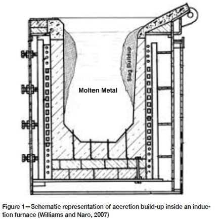
One of the operational difficulties that can be experienced when producing FeSi-15 using an induction furnace is accretion build-up. This is a phenomenon whereby slag, metallic oxides, or refractory oxide material (often with metal entrainment) adhere onto the refractory surface during the production cycle, thereby forming accretions on the refractory lining of the furnace (Figure 1, Williams and Naro, 2007). It has the undesirable effect of severely reducing the volume of the furnace, thus limiting the production capacity. As the accretion becomes part of the refractory lining, the lining becomes thicker which implies that during accretion build-up the coil efficiency decreases and the amount of electrical energy required to melt the charge increases (Naro, Williams, and Satre, 2018). The harder the accretion the more difficult it is to remove, and removal subsequently leads to mechanical damage of the refractory since a jackhammer is required to break the accretions from the refractory wall.
The induction furnace is shut down intermittently to allow for the removal of the accretions, inspection of the condition of the refractory material, and for repairs to the refractory lining. After a predetermined number of taps, the furnace is shut down for relining. The process of shutting down the furnace for routine cleaning and inspection exposes the refractory lining to a significant amount
of thermal shock, as well as mechanical damage to the lining when the accretions are removed. This reduces the usable life of the refractories and occasionally results in premature refractory failure. Overall, the stoppages lead to significant losses in production time (approximately 20% downtime) and revenue due to low production volumes.
The objective of this study was to investigate the effect of different impurity levels in the ferrosilicon feed material on accretion attachment, the extent of accretion growth, and ease of accretion removal.
Background
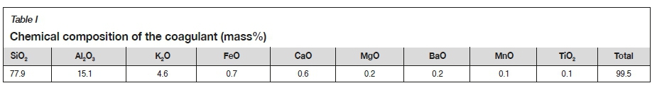
Induction furnace melting plants use different production cycles suited to the particular alloy produced. In the case of Exxaro FerroAlloys the following production sequence is used. Crude FeSi-75 and low-carbon shredded scrap are batched through the raw materials batching system into a 500 kg holding bin, according to a predetermined recipe. This recipe is based on the chemical composition of the crude FeSi-75 and the low-carbon scrap. Two induction furnaces with installed SAVEWAY@ systems, which provide continuous measurement of the lining thicknesses during operation, are used for the production process. While the first furnace is being tapped, which takes approximately 1 hour, the second furnace is charged with a new batch and the charge melted. When the furnace is ready for de-slagging (1520-1540°C) a coagulant is added to the charge, which results in the formation of a slag layer on top of the alloy. This slag is removed from the alloy using a metal spoon as it has adverse effects on tapping and atomization due to its rapid cooling rate, which causes runner build-ups and tundish blockages. The coagulant contains mostly silica and alumina with approximately 5 mass% potassium oxide as a fluxing component (Table I). The resulting slag is Al2O3-SiO2-CaO-based, but also contains FeO, MgO, BaO, K2O, and MnO in low concentrations. XRD analysis of this slow-cooled slag indicated that it contains corundum as the only crystalline phase. After de-slagging, the metal is heated to the tapping temperature of between 1580°C and 1600°C. The hot face of the refractory lining can therefore reach a maximum temperature of 1600°C.
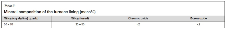
The furnace lining is a silica-based dry vibratable refractory material consisting of fused silica grains, crystalline quartz, chromic oxide, and boron oxide as the bonding agent and sintering additive (Table II). An Al2O3-based plaster material is used to seal the top or mouth of the furnace to prevent any loose furnace lining material from falling into the furnace, and also to patch damaged areas of the furnace after cleaning in order to prolong the life of the refractory lining. Each furnace lining is typically installed after 5 days of operation. The chemical composition of the plaster material is given in Table III. It can be assumed that the temperature at the mouth of the furnace is significantly lower than 1600°C, and that the plaster material will bond to the SiO2 lining through the formation of mullite (3Al2O3.2SiO2).
Literature survey
Accretions form in different high-temperature processes. In some instances accretion formation is unwanted because it reduces the working volume of the reactor and hinders material flow through the reactor. This is typically the case of accretion build-up in induction furnaces and ring formation in rotary kilns (Chatterjee and Mukhopadhyay, 1983). However, sometimes a thin, stable accretion layer may be desirable to protect the underlying refractory material and ensure containment of the molten alloy and slag in the furnace. This is the case when the refractory is force-cooled to form and maintain a freeze lining of slag on the refractory surface (Pistorius, 2003, 2004).
Karakus, Hagni, and Moore (1989) identified alloying elements, components from the refractory material, and some oxides released from the raw material charged to the process as sources that contribute to accretion formation. They identified furnace temperature, chemistry of the slag and melt, and furnace atmosphere as the factors influencing the attachment of the accretion onto the refractory lining.
Singh (1974) described two possible theories on the creation of primary insoluble oxides:
➤ Oxygen (air) diffusing through the porosity of the refractory lining towards the alloy, followed by oxidation of molten metal
➤ The slag impurities contained in the primary metal source or from the ferroalloys used in the melt combine to form accretions.
Various studies on the mechanisms of accretion formation identified the presence of an initial liquid oxide phase (slag) as a necessary precursor. Garbers-Craig and Coetsee (1996) found that liquid phase formation is the first step required to enable solid material to become attached to the refractory lining and enhance accretion growth. They further established that a silica-rich (SiO2) liquid phase fluxed with Al2O3 and CaO from the charge alloys provided the initial liquid oxide phase. Garbers-Craig and Coetsee (1996) concluded that the PO2at the refractory-alloy interface is set by iron and ferrosilicon in the furnace, so that only a small fraction of silicon and iron is expected to be oxidized at the typical melt temperature of 1600°C. Therefore, the PO2 associated with the ferrosilicon alloy far exceeds the equilibrium PO2 for the Al/Al2O3 equilibrium and the aluminium in the feed material will easily oxidize to Al2O3. Similarly, any elemental calcium as contaminant in the feed ferrosilicon will be oxidized to CaO. Therefore, any air entering the furnace through the refractory porosity as described by Sing (1974) will easily oxidize aluminium and calcium to their respective oxides. The phases that form will be based on the oxides of the impurities in the charge raw materials. It is therefore expected, that Al2O3, CaO, MgO, MnO, FeO, and SiO2 will react to form the final accretion phases.
Naro, Williams, and Satre (2006) explained that accretion build-up begins when a slag with a liquidus temperature above the liquid metal temperature cools to below its solidus temperature due to it being in contact with the colder refractory lining. The solid slag adheres to the refractory wall, forming a bond with the refractory material and over the period of production grows to form an accretion or build-up. Williams and Naro (2007) described the growth or build-up mechanism of the accretions as following the characteristic nucleation and crystalline growth route. The surface of the build-up consists of the same primary phase as that which precipitates from the liquid slag according to the equilibrium phase diagram.
Magwai (2005) identified corundum (Al2O3) and two different calcium aluminosilicates in the accretions removed from a coreless induction furnace. In his investigation into the hardening of the accretion he distinguished between a 'normal' or soft accretion and an 'abnormal' or harder accretion. The proportions of CaO and Al2O3 in the accretions differed, which pointed to the sources of the impurities as the reason for the difference in textures of the two samples. The initial work by Magwai (2003) indicated that the 'normal' accretion consists of mullite and a silica-rich phase.
In conclusion, accretions can be completely eliminated from the refractory walls, but this may be detrimental to the refractory lining since it might then be exposed to erosion and chemical attack. It is therefore important to understand how a thin, protective accretion layer attached to the refractory wall can be retained.
Experimental
Analysis techniques
Low-carbon shredded steel scrap (routinely cut-off strips from rolled coil) and different grades of crude ferrosilicon were used as feed materials in four trials during which FeSi-15 was produced. The shredded scrap is screened before being batched. During screening a dust, composed mainly of iron oxide and SiO2, is separated from the scrap. Any rust that is not removed during screening but which remains on the scrap will, however, enter the furnace. Varying scrap qualities can therefore lead to varying amounts of iron oxide entering the furnace.
The raw materials were sampled before each test. Chemical compositions were determined using ICP-OES (inductively coupled plasma-optical emission spectrometry), crystalline phases were identified using XRD (X-ray powder diffraction), and phase analysis was performed using SEM-EDS (scanning electron microscopy-energy dispersive X-ray spectroscopy). The carbon content of the low-carbon steel was determined using LECO CS 230.
Samples for XRD analysis were crushed and pulverized to passing 75 μηι using a tungsten carbide ball and milling pot. A PANalytical X'Pert Pro powder diffractometer fitted with X'Celerator detector operated at 25°C, 50 mA, and 35 kV, was used to analyse the samples. The crystalline phases were determined using X'Pert Highscore Plus software, while their relative amounts (mass%) were estimated employing the Rietveld method using X'Pert Highscore Plus.
Phase characterization was performed using a JEOL JSM IT300 SEM with Oxford X-Max50 energy-dispersive spectrometry (EDS) and Aztec software. The machine was operated under the following conditions: 15 kV, live time of 60 seconds, processing time of 4 seconds, and working distance of 10-11 mm. The phase compositions determined by EDS were reported in atom% and the stoichiometries of the oxides calculated with the assumption that Si is present as SiO2, Al as Al2O3, Mg as MgO, Ca as CaO, Cr as Cr2O3, and Fe as FeO.
Plant trials
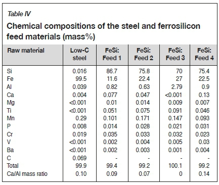
FeSi-15 was produced by melting the high-grade crude ferrosilicon (FeSi-75) and diluting it with low-carbon steel scrap in a 3.5 t medium-frequency coreless induction furnace (Table IV). Four different types of crude ferrosilicon (Feeds 1-4, Table IV) with different impurity ratios were used to establish the effect of these impurities on the thickness and texture of accretion build-up. XRD analysis confirmed that all four feed ferrosilicon samples consisted of silicon (Si) and ferdisilicide (FeSi2) as crystalline phases. The main alloying component in the steel was manganese (0.29 mass%), while the crude ferrosilicon contained aluminium, calcium, and manganese in trace amounts (Table IV). The aluminium content in the crude ferrosilicon varied between 0.6 and 2.8 mass%, the calcium between <0.001 and 0.1 mass%, and the manganese between 0.1 and 0.2 mass%. The different ferrosilicon feeds were classified according to impurity aluminium and calcium concentrations as follows: Feed 1 as medium Al and low Ca, Feed 2 as medium Al and low Ca, Feed 3 as high Al and zero Ca; Feed 4 as medium Al and medium Ca. The Ca/Al mass ratios in the different feeds thus varied between 0.00 and 0.14. The start-up of all four tests followed the same procedure: from the batching plant low-carbon steel shredded scrap was added first into holding bins, followed by the FeSi-75. The batched recipe was then loaded into a vibrating feeder. Since the shredded scrap was at the bottom of the bin, it came in contact with the hearth of the furnace first. More low-carbon steel was required to produce the product grade of FeSi-15 in Feed 1 as the raw FeSi-75 of Feed 1 was very enriched in silicon (> 86 mass%).
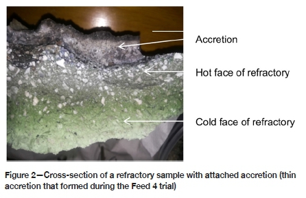
At the end of each refractory lining campaign, the number of taps carried out and qualitative aspects on the ease of accretion removal and extent of accretion build-up were noted. Samples of the refractory material with attached build-up were taken at various points inside the furnace. Each sample was cross-sectioned from the hot face of the accretion to the cold face of the lining (Figure 2). Subsamples were then removed from the hot face of the accretion, the interface between the accretion and lining material, and from the cold face of the lining. These samples were prepared for XRD and SEM-EDS analyses.
Results
Observations
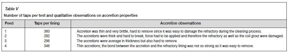
The number of taps per lining, as well as the thickness and strength of each accretion and the effort required to remove it, were noted (Table V). The largest number of taps per lining was achieved in the trials with Feeds 1 and 4, during which thin accretions formed. The only accretion that was easy to remove was the one formed in the Feed 4 trial.
XRD analysis
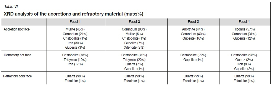
Crystalline phases identified in the hot faces of the accretions, as well as the hot and cold faces of the refractory, are shown in Table VI. The hot faces of the accretions were mostly oxide-based, with low concentrations of alloy phases. Fe3Si occurred in all accretions, with metallic iron also present in the accretion of Feed 1 and Fe5Si3 in the hot face of the Feed 2 accretion. The accretions that formed with Feeds 1 and 2 contained mainly corundum and mullite as crystalline phases, while the accretion of Feed 3 contained corundum and anorthite, and that of Feed 4 hibonite and corundum. The sintered hot faces of the silica-based refractory samples were transformed into cristobalite, while the cold faces consisted of a combination of quartz and 1 mass% eskolaite. The presence of mostly cristobalite at the hot face of the refractory implies that the accretion-refractory interface temperature reached at least 1470°C (Muan, 1965). Metallic iron and Fe3Si particles extended up to the accretion-refractory interface in all four trials.
SEM-EDS analysis
Hot faces of the accretions
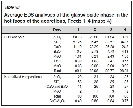
Backscatter electron (BSE) Images of the hot faces of the accretions that formed in the Feed 1-4 trials are shown in Figures 3 to 6. A glassy oxide phase (which can be distinguished as the light grey matrix phase that contains alloy droplets and darker grey crystals) could be identified in all four accretion samples. This oxide phase was liquid under operating temperatures and remained as a glassy phase after cooling. Crystalline corundum and gupeiite alloy droplets are common to the hot faces of all accretion samples. Mullite could also be distinguished in certain areas of the hot face of the Feed 1 accretion, while needle-shaped anorthite could also be found in the Feed 2 and Feed 3 accretions. The amount of glassy oxide is higher in the hot faces of the Feed 1 and 4 samples, intermediate in the hot face of Feed 3, and the lowest in the hot face of Feed 2. The glassy oxide phase associated with the hot faces of the accretions are all CaO-Al2O3-SiO2-based, with MgO, BaO, and FeO in low concentrations (Table VII). The glassy oxide phase in the hot faces of the accretions that formed from feeds 2-4 are similar, with CaO/Al2O3 mass ratios in the order of 0.8, while in the case of the Feed 1 accretion the CaO/Al2O3 mass ratio of the glassy phase is 0.4, with a significant higher SiO2 content.
Phase chemistry of the mid-sections of the accretions
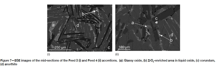
The mid-sections of the accretions consist of corundum, mullite, and a glassy oxide phase in certain areas, and anorthite together with corundum and glassy oxide in others. Gupeiite could be detected throughout the accretions. The mid-sections are particularly crystalline and dense, with low concentrations of the glassy oxide phase (Figure 7). Low concentrations of ZrO2 could also be detected in the mid-sections of the accretions that formed from Feeds 3 and 4.
Phase chemistry of the accretion-refractory interface
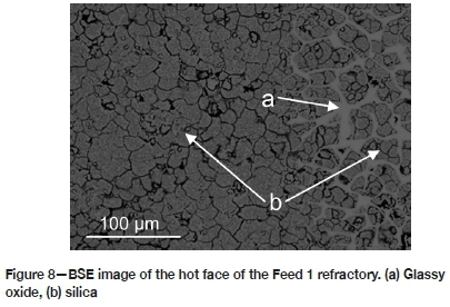
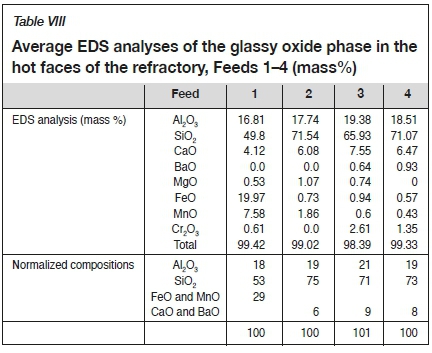
The accretion side of the accretion-refractory interface consists of either a glassy oxide phase and corundum (Feed 1), glassy oxide phase and mullite (Feeds 2 and 4), or glassy oxide phase, corundum, and hibonite (Feed 3). Only a glassy oxide phase and SiO2 were detected in the hot face of the refractory at the accretion-refractory interface. This phase is (Fe,Mn)O-Al2O3-SiO2-based in Feed 1 (Figure 8), and CaO-Al2O3-SiO2-based in Feeds 2-4 (Table VIII). The composition of this CaO-Al2O3-SiO2-based glassy oxide phase is similar in Feeds 2--4, but contains significantly higher concentrations of SiO2 compared to the glassy oxide phase in the hot faces of the accretions. The CaO/Al2O3 mass ratios of this glassy oxide phase are also significantly lower than in the hot face of the accretion (0.3-0.4 vs. 0.8).
Discussion
Since the coagulant is added to the furnace when the alloy temperature is just above 1500°C and the ferrosilicon is tapped when the alloy temperature is in the order of 1600°C, it is logical to consider the 1500-1600°C temperature range when the observed phase relations in the accretions are interpreted in terms of accretion attachment and build-up. At operating temperatures between 1500 and 1600°C the slags that are produced in the FeSi-15 smelting process are Al2O3-SiO2-CaO-based, with compositions that fall in the (liquid + corundum + anorthite) and (liquid + corundum) phase fields of the SiO2-CaO-Al2O3 phase diagram at respectively 1500 and 1600°C (indicated by the circles, Figures 9a and 9b). These slags are therefore not compatible with the SiO2-based lining, and chemical interaction between the slag and lining is expected.
Analysis of the accretion-refractory interfaces confirmed that the accretions attach to the lining through the formation of a liquid phase when oxides from the charge react with the SiO2 lining. Either a (Fe,Mn)O- and alumina-containing silica-rich liquid phase (Feed 1) or a CaO- and alumina-containing silica-rich liquid phase (Feeds 2-4) forms (Table VIII). The FeO and MnO in this liquid phase (Feed 1) result from the low-carbon steel, presumably due to oxidation but also to the rust layer on the shredded scrap (approximately 30% of the shredded scrap used on the plant contains a surface layer of rust). The CaO and Al2O3 in the liquid phase result from the oxidation of the Ca and Al impurity elements in the feed FeSi-75.
During operation the liquid phase at the accretion-refractory interface is highly viscous due to its high SiO2 content and serves to further attach oxidation products from the raw materials to the lining. As the aluminium and calcium from the feed continue to oxidize in further heats and react with the coagulant, an Al2O3-SiO2-CaO-based accretion builds up. The silica content of the accretions decreases, while the calcium oxide and alumina contents increase from the accretion-refractory interface towards the hot face of the accretion. Cooling and heating cycles associated with alternating cooling of the accretion during tapping followed by heating when the next heat is processed enhance the continuous growth and re-equilibration of phases in the accretion. This explains the densified microstructures of the middle sections of the accretions, which consist mostly of crystalline phases with very low concentrations of the glassy oxide phase.
The hot faces of the accretions consist of gupeiite (Fe3Si) and either (liquid + Al2O3 + mullite), (liquid + Al2O3 + anorthite), or (liquid + Al2O3 + CaO.6Al2O3). The (liquid + Al2O3 + CaO.6Al2O3) phase composition can exist at both 1500 and 1600°C, while the (liquid + Al2O3 + anorthite) phase combination exists only at 1500°C and the (liquid + Al2O3 + mullite) phase combination only at 1600°C (Figure 9). The main difference between the thin and thick accretion layers (Feeds 1 and 4 vs. 2 and 3) is the higher glassy oxide concentrations observed in the hot faces of the thin accretions. It is believed that higher concentrations of a liquid phase in the hot face of the accretion during operation limit accretion build-up as such a hot face layer can more easily be washed back into the molten alloy due to bath motion caused by electromagnetic stirring. It can be seen from the 1500 and 1600°C isothermal sections of the SiO2-CaO-Al2O3 phase diagram (Figures 9a and 9b) that higher CaO/Al2O3 mass ratios in the accretions will result in the formation of accretions with compositions closer to the all-liquid phase field. These accretions will therefore contain more liquid at temperature.
Since the accretion that formed in Feed 4 was the thinnest and easiest to remove, it can be concluded that accretion formation can be managed by limiting the total calcium and aluminium impurity content of the feed material, and by using a higher Ca/Al impurity ratio whereby the total solid oxides content in the accretion can be minimized. Using an alumina-based lining could also be considered, as such a lining will be more compatible with the initial Al2O3-rich slag that forms during start-up and which attaches the accretion to the lining.
Conclusions
Accretion build-up during the production of FeSi-15 was investigated by varying the impurity aluminium and calcium contents in the FeSi-75 feed material. The following conclusions can be drawn.
➤ Calcium and aluminium impurity components in the feed FeSi-75 are predominantly responsible for accretion buildup. These impurity components oxidize and react with the SiO2 lining and coagulant, respectively attaching and building up the accretion.
➤ The accretion attaches to the refractory lining through the formation of a liquid phase at temperature, which is either (Fe,Mn)O-Al2O3-SiO2- or CaO-Al2O3-SiO2-based. This liquid phase reacts with the SiO2 lining and penetrates it as the reaction proceeds. The iron and manganese oxides in this liquid phase presumably originate from the rust layer associated with some of the scrap that is used, as well as oxidation of the low-carbon steel during start-up of the furnace. These transition metal oxides only played a noteworthy role in the attachment of the accretion of Feed 1 to the lining, and not during accretion build-up.
➤ Since the lining is SiO2-based, the liquid phase that forms is SiO2-enriched and therefore highly viscous. This viscous liquid phase facilitates accretion build-up, through which phase combinations of CaO, Al2O3, and SiO2 attach in successive layers to the lining. Alloy particles are also entrapped in this liquid phase, although only in very low concentrations.
➤ It appears that a higher proportion of liquid to solids in the hot face of the accretion under operating conditions limits accretion build-up. This can be achieved through the use of a high Ca/Al impurity ratio in the FeSi-75 feed.
➤ The formation of accretions can be completely avoided, but this will expose the refractory lining to slag attack, which in turn will lead to premature refractory failure. It is hence important to leave a thin layer of accretion to protect the refractory lining from chemical attack by the slag. In order to achieve this it is recommended that the total calcium and aluminium impurity content in the FeSi-75 feed material should be as low as possible, but the Ca/Al impurity ratio must be high.
Acknowledgements
Sponsorship from Exxaro Resources and the assistance of Dr Alain Nyembwe with FactSage 7.3 are gratefully acknowledged.
References
Bale, C.W., Chartrand, P., Degteröv, S.A., Eriksson, G., Hack, K. Ben Mahföüd, R., Melancon, J., Pelton, A.D., and Petersen, S. 2002. FactSage thermochemical software and databases. CALPHAD, vol. 26, no.2. pp. 189-228. http://www.crct.polymtl.ca/fact/factsage/FactSage.pdf [ Links ]
Collins, B., Napier-Munn, T.J., and Sciarone, M. 1974. The production, properties, and selection of ferrosilicon powders for heavy-medium separation. Journal of the South African Institute of Mining and Metallurgy, vol. 75, no. 5. pp. 103-115. https://www.saimm.co.za/Journal/v075n05p103.pdf [ Links ]
Chatterjee, A. and Mukophadhyay, P.K. 1983. Flow of materials in rotary kilns used for sponge iron manufacture: Part III. Effect of ring formation within the kiln. Metallurgical Transactions B, vol. 14, no. 3. pp. 393-399. https://link.springer.com/journal/11663 [ Links ]
Garbers-Craig, A.M. and Coetsee, T. 1996. Investigation into the formation of accretions in the induction furnace at Iscor's Ferrosilicon Plant. Internal report, Iscor. [ Links ]
Karakus, M. Hagni, R.D., and Moore, R.E. 1989. Cathodoluminescence mineralogy of ceramic build-ups in channel induction furnaces. Process mineralogy IX: Applications to Mineral Beneficiation, Metallurgy, Gold, Diamonds, Ceramics, Environment and Health. Proceedings of the International Symposium on Applied Mineralogy (MAC-ICAM-CAM), Montreal, Quebec, Canada, 14-17 May 1989, and the Process Mineralogy Symposium, Las Vegas, Nevada, 27 February - 2.March 1989. Petruk, W. (ed.). The Minerals, Metals & Materials Society, Warrendale, PA. pp. 441-458. [ Links ]
Magwai, M.K. 2003. Investigations into the hardening of accretions in the coreless induction furnaces at Kumba Ferrosilicon. Internal report, Kumba Ferrosilicon. [ Links ]
Magwai, M.K. 2005. Investigations into the hardening of accretions in the coreless induction furnaces at Kumba Ferrosilicon. Internal report, Kumba Ferrosilicon plant. Unpublished. [ Links ]
Muan, A. and Osborn, E.F. 1965. Phase Equilibria Among Oxides in Steelmaking. Addison-Wesley. Reading, MA. 179 pp. [ Links ]
Naro, R.L., Williams, D.C., and Satre, P. 2006. Control of slag and insoluble build-up in ladles, melting and pressure spout furnaces. ASI International, Ltd. http://asi-alloys.com/pdf/ControlofSlag.pdf [ Links ]
Naro, R.L., Williams, D.C., and Satre, P. 2018. Economic consequences of insoluble buildup on coreless melting efficiency, ASI International, Ltd. pp. 52-55. https://www.asi-alloys.com/pdf/ASI_SS_Fall2018_Eng.pdf [ Links ]
Pistorius, P.C. 2003. Fundamentals of freeze lining behaviour in ilmenite smelting. Journal of the South African Institute of Mining and Metallurgy, vol. 103 , no. 8. pp. 509-514. https://wwww.saimm.co.za/Journal/v103n08p509.pdf [ Links ]
Pistorius, P.C. 2004. Equilibrium interactions between freeze lining and slag in ilmenite smelting. Journal of the South African Institute ofMining and Metallurgy, vol. 104 , no. 7. pp. 417-422. Corpus ID: 131142276 [ Links ]
Singh, S.N. 1974. Mechanism of alumina buildup in tundish nozzles during continuous casting of aluminum-killed steels. Metallurgical Transactions, vol. 5, no. 10. pp. 2165-2178. https://doi.org/10.1007/BF02643930 [ Links ]
Williams, D.C. and Naro, R.L. 2007. Mechanism and control of buildup phenomenon in channel induction and pressure pouring furnaces - part 1. ASI International, Ltd. https://www.asi-alloys.com/pdf/Buildup%20%20Phenomenon%20in%20Channel%20furnaces%20DIS%202007.pdf ♦ [ Links ]
 Correspondence:
A.M. Garbers-Craig
Email: Andrie.Garbers-Craig@up.ac.za
Received: 21 Feb. 2020
Revised: 28 Oct. 2020
Accepted: 27 Jan. 2020
Published: February 2021
ORCID:
T.M. Nemavhola https://orchid.org/0000-0001-7352-0734
T. Coetsee https://orchid.org/0000-0003-2028-5755
A.M. Garbers-Craig https://orchid.org/0000-0002-0298-8097

