


Services on Demand
Article
 English (pdf)
 Article in xml format
 Article references
Indicators

Related links
-
 Cited by Google
 -
 Similars in Google
Share

 Permalink
Journal of the Southern African Institute of Mining and Metallurgy
On-line version ISSN 2411-9717
Print version ISSN 2225-6253
J. S. Afr. Inst. Min. Metall. vol.121 n.2 Johannesburg Feb. 2021
http://dx.doi.org/10.17159/2411-9717/1274/2021
MINE HEALTH AND SAFETY PAPERS
Blasting and preconditioning modelling in underground cave mines under high stress conditions
E. CórdovaI; I. GottreuxII; A. AnaniI; A. FerradaI; J.S. ContrerasIII
IMining Department, Pontificia Universidad Católica de Chile, Santiago, Chile
IIOrica, Chile
IIIFaculty of Engineering, Universidad del Desarrollo, Chile
SYNOPSIS
Cave mining is an underground mass mining technique. The largest projects, which are known as 'super caves', produce hundreds of thousands of tons of ore per day, which involves large footprints with considerable column height, and have a life of mine of over 20-40 years. These operations are typically located deep, under high stresses and in competent rock masses, making initiation and propagation of the caving process harder to manage. These challenges must be confronted by optimizing the fragmentation of the orebody to achieve smaller size blocks that will result in consistent caving and improved flow of the ore from the drawpoints. To achieve better performance from the drawpoints, preconditioning is applied to fragment and damage the material required to cave.
We present a proposed design for preconditioning in underground mines, considering the challenges that these large-scale mines are already facing, based on a comprehensive analysis of current design parameters, case studies, and sensitivity analyses using numerical models.
Keywords: fragmentation, preconditioning, caving, blasting, structures, stresses, explosives.
Introduction
Caving operations undermine a massive orebody to initiate the collapse, comminution, and flow of the ore to multiple drawpoints. Cave mining operations are facing greater challenges due to greater depths. In Chile, some mines are up to a kilometre deep, such as the Chuquicamata Underground and the El Teniente New Mine Level copper projects. Besides the depth of the mines, the rock mass presents challenging characteristics, with fewer open structures, or joints filled with cohesive material; both conditions causing difficulties for the mining process, the caving of the ore, fragmentation, and seismicity. The problems associated with the mine's operation impact safety, operational continuity, and ultimately business sustainability.
To mitigate the difficulties, preconditioning (PC) has been implemented in Chile to weaken the rock mass by hydraulic fracturing (HF), and this has shown favourable results in terms of the seismic response of the cave. In addition to HF, preconditioning with explosives (DDE or dynamic debilitation with explosives) has been used, on its own or in combination (HF+DDE) to produce a beneficial effect on induced seismicity, and reduce the frequency of hang-ups, and oversized boulders at the drawpoints. However, the fragmentation obtained with current preconditioning techniques has not shown a huge improvement, and fragmentation remains one of the most critical aspects in caving mines. The work presented in this paper describes the modelling process for alternative forms of preconditioning to optimize fragmentation of the rock mass.
State of the art
Types of preconditioning
Preconditioning essentially involves treating the rock mass prior to caving, under natural confinement conditions, with an appropriate process to generate fractures by activating the in-situ structural network, or by explicitly creating a set of new fractures. The main purpose is to weaken the competent rock mass in the primary domain material.
There are three main ways to precondition the rock mass for caving.
Preconditioning with hydraulic fracturing (HF)
Hydraulic fracturing is a technique adapted from the oil industry. A section of a borehole in the rock mass is isolated with pressurized packers and a fluid (usually water) is injected up to a pressure that will initiate and propagate a tensional fracture through the rock mass. The boreholes are oriented such that the fractures propagate in the plane of the principal stresses σ1 - σ2, so they open up in the minimum principal stress direction σ3. The application of this technique has resulted in a reduction in significant seismic responses due to the caving of the rock mass, reducing the seismic hazard1.
Preconditioning with explosives
Blasting is carried out under confined conditions, without any free faces present. The objective is to produce new fractures and reduce the overall strength of the rock mass. The placement of initiation points along the charges and the inter-hole timing can be selected to promote stress wave interaction to enhance the resulting damage in the rock mass.
Mixed or intensive preconditioning:
Catalán et al. (2012) describe preconditioning using a combination of both techniques (HF+DDE) in order to improve the initiation of the cave, its propagation, and to ensure primary fragmentation of the in-situ rock mass that will allow high extraction and productivity rates.
Pre-conditioning experiences in caving mines
Codelco, Division Andina, Chile
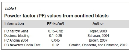
Brown (2007) describes preconditioning with explosives in caving mines based on a test blast performed by Sougarret et al. (2004) in Andina, with 19 holes on a 26 m by 13 m pattern, with a hole diameter of 140 mm and a length of 100-112 m, charged with bulk emulsion. This translates into a low powder factor of around 0.045 kg/m3, and it is surprising that the results showed a significant change in the fragmentation of the rock mass: the in-situ block size of 2 χ 1 m being reduced to a P80 of 1.4 to 0.7 m at the drawpoints. There was no significant change in the size for the smaller fragments, < 0.5 m.
Newcrest, Cadia East 1, Australia
In 2012, Dyno Nobel, conducted a trial in a panel at Cadia East at a depth of 1200 m. Blast-holes 150 m long were charged with a specially formulated emulsion and 20 m of stemming. The blast produced significant fracturing in the rock mass adjacent to the blast-holes. The improvement due to finer fragmentation was manifest through the longer time between interruptions at the drawpoints, and a concomitant increase in the production rates.
Newcrest, Cadia East 2, Australia
A larger scale pre-conditioning trial was performed in Cadia East by Catalán, Onederra, and Chitombo (2012). The layout of the holes was tighter, with a pattern of 14.2 χ 14.2 m, with holes 165 mm in diameter of, and 150 m in length. Each hole was charged with 3.2 t of emulsion, and 20 m of stemming. The design had a powder factor of 0.12 kg/m3 with initiation points every 8 m along the charge length. The initiation design was developed through numerical modelling, which indicated that the high density of initiation points would create localized areas of stress interaction that would generate zones of increased damage.
Pre-conditioning experimentation at Codelco, El Teniente, Chile
Brzovic et al. (2014) compared preconditioning by HF and by blasting. Overall, the pre-conditioning generated new fresh primary fractures within a competent rock mass. HF produced certain beneficial effects; the occurrence of large boulders was reduced from 0.8% to 0.2% when blasting was used, to almost zero when the spacing between the blast-holes was reduced. After the blasting tests, core drilling was carried out, and mapping of the core showed that the maximum extension of the generated fractures was 8 m and the minimum extension was 0.5 m, with an average extension of 5 m.
Modelling
Using the hybrid stress blasting model (HSBM), Onederra, Catalan, and Chitombo (2013), demonstrated a reduction in the extension of the blast-induced fractures according to the depth and stress concentration of the area. They calculated that the radius of exent for fractures to a depth of 500 m was in the order of 3.5 to 4 m, while at 1500 m depth it was only in the order of 1.5 m.
Castro et al. (2014) simulated six variations of preconditioning techniques, changing the size of the blocks of rock and evaluating these changes according to the response of flow, productivity, costs, and processing. The results showed that blasting the confined rock mass increased the flow of material and the productivity, especially when the spacing between the HF was greater. Combining the types of preconditioning was more expensive, although it led to a greater improvement in the overall mining rates and an overall reduction of costs.
Rock mass characteristics to consider
Nowadays designs for preconditioning with explosives are made based on numerical modelling, combined with advice from experts, and the designs are then adapted to the layout of the mine. There is no design methodology for preconditioning in mines using caving techniques. The amount of information is limited to that presented in Table I, which shows the powder factors used in different preconditioning tests. The closest design methodologies are for massive destress blasting: a graph of the design for destress blasting (Brummer and Andrieux, 2002) that compares the total explosive energy to use depending on the rock mass being conditioned, with a value between 200 and500 cal/kg, and an index of destressing capability (Andrieux and Hadjigeorgiou, 2008) that defines the critical parameters that control a blast for destressing, and the study between the interactions among the parameters by using a matrix of interaction RES (rock engineering system).
Rock mass under high stress confinement
The deepening of underground mines has resulted in efforts to cave a rock mass under high stress conditions, and as a result, the mining-induced stress is also increased. A rock mass under high stress can be defined as an area of the mine where the depth and mining-induced stresses have the potential to cause geomechanical issues that could impact production.
Rock mass properties
It is important to take into account the fact that the rock mass will behave differently under different load conditions. Static properties are usually used for calculating the resistance to failure of the rock. However, Prasad (2000) presents (Table II) a relationship between the deformation velocity and the applied stress.
From Table II, for a blast with a high detonation velocity and a high rate of energy transmission into the rock, it can be seen that dynamic rock properties should be used instead of the static properties.
Starzec (1999) compared the static and dynamic Young's modulus for 300 tests on five different rock types. The results indicated that the dynamic Young's modulus is higher than the static modulus for rock material. Blanton (1981) proved that the resistance to dynamic compression is in the order of 1.5-2.5 times that for static compression, and Prasad (2010) indicated that the factor varies between 2.5 and 4.6 times. At the same time, the dynamic tensile strength also increases as the deformation velocity increases. Cho, Otaga, and Kaneko (2003) obtained a difference between the resistance to the dynamic and static traction of between 2.1 and 13 times. This explains why material failure models using static parameters usually predict fractures that extend a long way, while dynamic analyses indicate greater resistance to the waves travelling from the explosion. It is recommended that numerical models be built that use dynamic rock properties, which are more capable of representing the fracture generation and propagation in the rock mass, especially when a high-resolution seismic tomography campaign can provide the dynamic properties of the rock mass.
In-situ structures
Empirical evidence shows that the resistance of a competent rock mass to caving is controlled mainly by the tensile strength of its network of discontinuities. The preconditioning results of Baéz et al. (2014) show that horizontal structures limit the extent of the fractures induced by blasting by only a few centimetres. However, in the case of vertical structures, the results show a loss in symmetry around the charge, where the greatest impact is in the direction perpendicular to the plane of the structures.
In-situ stress
Using laboratory tests Jung (2001) showed that confinement of the rock mass reduces the extension of the fractures, and that the fractures align in the direction of the major principal stress. Aydan (2013) came to the conclusion that in the case of anisotropic stresses, fracturing extends further from the blast-hole in the direction of the minimum principal stress. Furthermore, Aydan showed through laboratory experiments and full-scale tests that the extension of the structures is affected much more by the anisotropy of the in-situ stress than by the highly fragmented area.
Preconditioning design and modelling
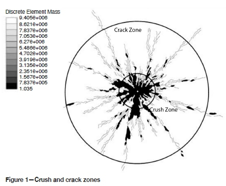
Modelling in this study was undertaken with the Mechanic Blasting Model (MBM), capable of simulating the non-ideal detonation of the explosive in a blast-hole, the stress/strain effects induced in the surrounding rock mass, the dynamic influence of the gases from the charge, and the evolving fracture network through to the final post-blast damage state of the rock mass (Minchinton and Lynch, 1996). MBM is based on the large ELFEN dynamic finite/discrete element code (Owen, Munjiza, and Bicanic, 1992) with pre- and post-processing extensions. The numerical simulations are evaluated in terms of the generation and extension of fractures, and the percentage of elements damaged within the crush and crack zones (primary fragmentation) indicated in a two-dimensional plane strain model of a horizontal section through a blast-hole (Figure 1). All this is due to the restrictions associated with escalating a primary to secondary fragmentation (comminution through the flow of the caving material) (Eadie, 2002).
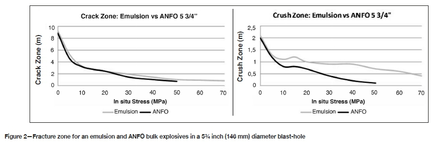
Initial work investigated the influence of increasing in-situ stress on the extent of the crack and crush zones for two bulk explosives, ANFO and a straight emulsion, in a 5¾ inch (146 mm) diameter preconditioning blast-hole with no free face.
Figure 2 shows that the emulsion induces more damage in the rock mass, with the greatest effect in the crush zone.
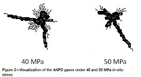
The higher detonation pressures in the emulsion will produce higher amplitude stress waves in the rock mass around the blast-hole compared to ANFO. Due to geometric spreading of the waves as they travel through the rock, and the stress waves having to overcome the in-situ stress condition, the higher amplitude stress waves will have the greatest effect in creating new fractures closer to the blast-hole, hence more damage in the crush zone. Despite the ANFO charge having a lower detonation pressure, the confined rock mass traps the explosive gases in the blast-hole and the pressure flows down the dominant radial fractures (Figure 3), which will aid their formation.
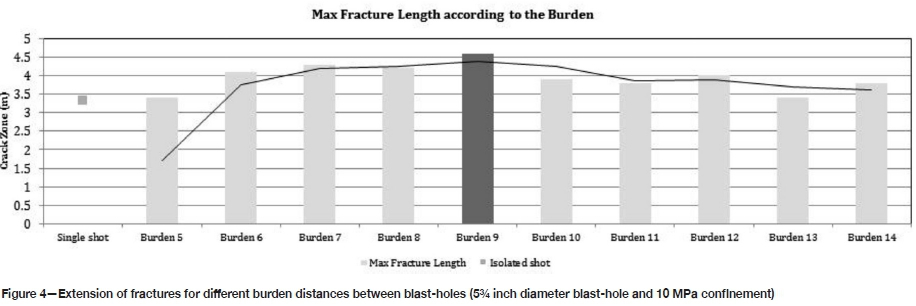
Blast-holes for preconditioning will not be fired in isolation, and so analysis of the influence of different hole separation distances (burden/spacing) on the resulting fracturing is important in maximizing the benefit of explosive preconditioning (Figure 4). The modelling indicates that for two 5¾ inch diameter blast-holes initiated on the same delay, in rock with 10 MPa ínsita stress, the maximum crack extension will be achieved at a 9 m blast-hole spacing at 4.5 m (half the hole spacing), 50% more than for a single blast-hole at 3 m crack extension. The crack extensions for 7 m and 8 m blast-hole spacings are slightly less than for 9 m spacing, while at 10 m spacing the crack extension decreases to less than 4 m.
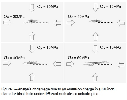
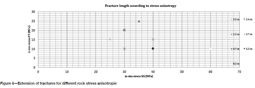
Influence of in-situ stresses
The influence of in-situ stress anisotropy on blast induced radial fracture length was investigated by varying the stress on the X and Y axes of the model. The fracture networks for different in-situ stress conditions show that the larger the stress anisotropy the greater the fracture length in the direction of the larger stress condition (Figure 5).
Once the extent of the damage is characterized for the type of explosive, hole diameter, and in-situ stress condition, it is important to investigate the influence of initiation configuration timing on damage in the rock mass. The results of the analyses show that the simultaneous detonation of holes leads to an overall better level of effectiveness in terms of interaction and extension of fractures, and this validates the pre-cut blast-hole theory. Therefore, it is recommended that primers be positioned every 8 m in the explosive column and initiated all on the same delay. It is also recommended to offset the position of the primers in adjacent holes, so that the stress waves are initiated at different levels, producing a more even fracture network between the blast-holes.
Interaction of blasting with hydrofractures
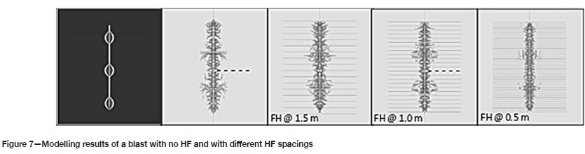
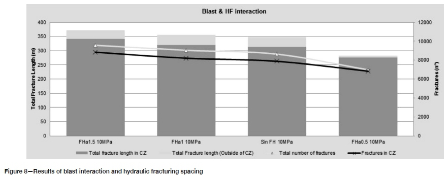
When evaluating the potential performance of the mixed preconditioning it is important to assess the influence of a campaign of HF on the subsequent blast-induced preconditioning (DDE). The modelling scenarios are based on common industry HF practice and utilize axisymmetric model geometries with the axis of the blast-hole on the line of symmetry. The analysis of
the damage induced in the rock mass only quantifies the new blast-induced fractures, not the fractures produced by the HF; however, the influence of the existing HF fracture network on the blast-induced fractures is modelled. The scenarios are: no HF, and HF on 1.5 m, 1.0 m, and 0.5 m spacings, considering two holes spaced at 1 m and overlapping between them.
The modelling indicates that across the four scenarios, the greatest blast-induced fracture length is achieved with HF on a 1.5 m spacing (Figures 7 and 8). As the HF spacing is reduced, the blast-induced damage is reduced, due to greater dispersion of stress wave energy through refraction and reflection of the waves between the HF fractures. From Figure 8 it can be seen that in the modelled scenarios no more than 10% of the total fracture length is generated in the crack zone (beyond the crush zone).
Influence of rock mass conditions
To investigate the interaction between multiple blast-holes, plan view geometries on a horizontal section were constructed. The models assessed the influence of variations in discontinuities (structure), in-situ stress, and blast-hole pattern (Figure 9).

The results show that with fewer structures (Figure 9a), long fractures are generated between blast-holes in the direction of the principal stress; with more structures the radial fracture pattern around each blast-hole is more uniform (Figure 9b).
A staggered layout of the holes will show an improvement if there is stress anisotropy in the area, by generating a better blast interaction between the holes than when they are drilled on a square grid pattern.
From the previous analyses, it can be determined that for medium to high in-situ stresses there will be no connection of the fractures from neighbouring blast-holes. Therefore, there would be little reduction in the size of the larger blocks of rock. On the other hand, actual tests in the mines have shown an improvement in fragmentation at the drawpoints (Cerruti, 2009). This indicates that despite the accumulated primary fracturing due to blasting being uneven through the rock mass and potentially in isolated regions, there is still improved comminution through the cave flow to produce finer material.
Blasting to a void
Even though blast-induced preconditioning is confined, without a free face, it is interesting to explore new design alternatives, and to investigate how they would perform with an available free face (pilot hole) or 'dirty face' (a face not completely free, with a certain percentage of broken material from a previous blast). Figure 10a shows the resulting damage and initial movement when firing to a free face on the right, and in Figure 10b the same blast parameters are applied to a confined condition with in-situ stresses and only a 1.5 m diameter hole to provide relief on the right, showing the reduction in fracturing, with the radial fractures not even extending to the void hole.
In the model in Figure 10b the 7 m separation between the blast-hole and the void hole was too large to influence the fracturing at the blast-hole. Therefore, further models were run with smaller distances between the blast-hole and the void hole (Figure 11). The results show that at 3 m separation the void hole has a significant impact on the fracturing between the void hole and the blast-hole, to the extent that the rock mass at the void hole has completely failed and material has moved into the void. However, at 4 m separation, damage has accumulated at the void hole, but the rock has not failed.
Further modelling investigating the influence of a range of void hole diameters (0.5 m, 0.75 m, 1.0 m, and the 1.5 m) showed that more damage accumulates in the rock mass with a larger diameter void hole, as one would expect.
Proposed preconditioning design
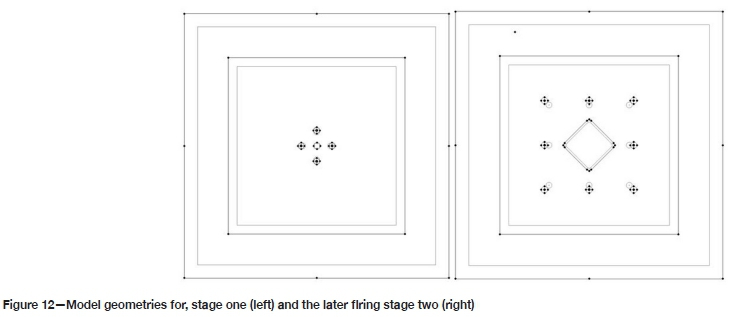
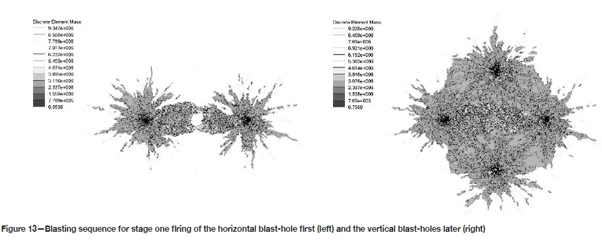
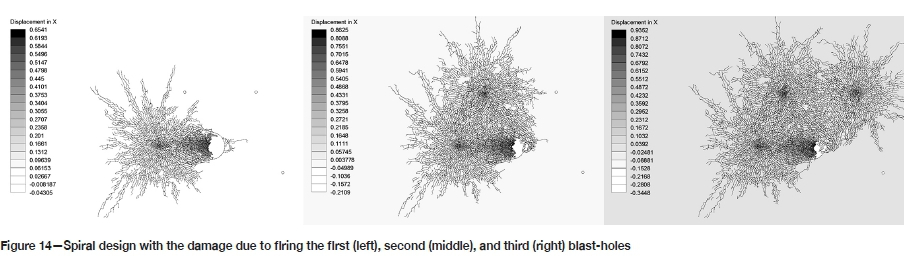
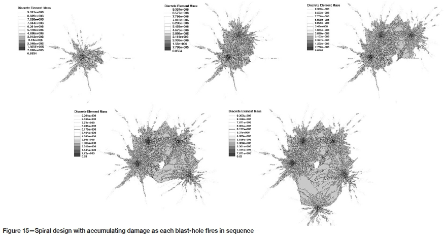
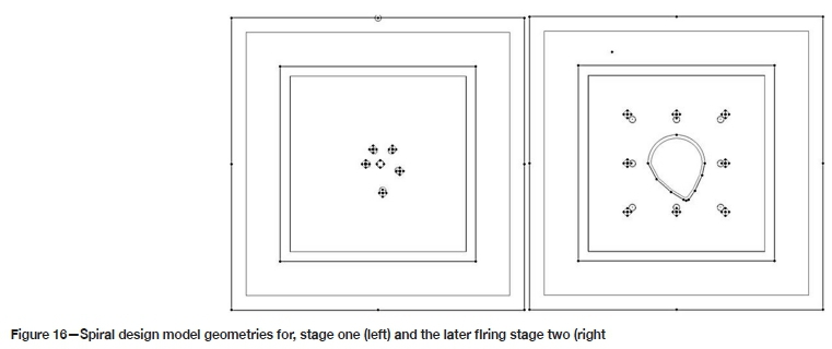
The design utilizes the significant increase in damage that blasting to a void can achieve compared with more conventional confined precondition blasting, with the understanding that further comminution occurs in the cave flow. Therefore, the primary fragmentation can be coarser than the final fragmentation obtained in the drawpoints. The design borrows from drawbell blast design, where a central pilot hole provides an initial void for the first blast-holes to fire into, which then in turn provides subsequent relief for later firing blast-holes further from the centre. Figure 12 shows the plan view model geometries for the design, divided into two stages. A 1.5 m diameter pilot hole is located in the middle, and then the first stage initiates the first four blast-holes, each located 3.5 m away from the pilot hole in the sequence shown in Figure 13 to produce a fragmented rock mass between the four blast-holes. The square hole pattern is effective in underground development burn cuts, for example, due to the high powder factor in the blast design. However, in designs with a lower powder factor a spiral configuration of blast-holes can be applied to fracture a greater volume of rock and increase the effective free face. The application of this spiral design is shown in Figures 14 and 15. In Figure 14 the sequence of blast-hole firing results in a consistent direction of movement as each blast-hole fires, as opposed to the sequence of blast-holes firing in the square pattern (Figure 13) with blast-hole material moving against the opposing blast-hole. Figure 15 shows the final breakout for the spiral design.
Figure 16 shows the spiral design as stage one of the two-stage model, with the second stage the same as that for the square design (Figure 12) with a 10 m spacing of the perimeter blast-holes.
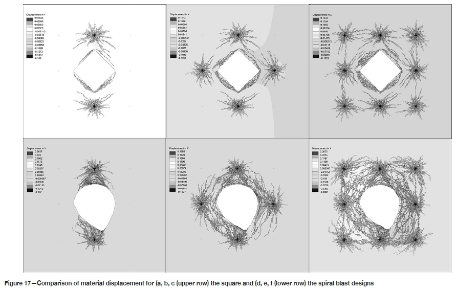
Figure 17 compares the evolution of the fracture network as the blast-holes in stage two fire for the square design and the spiral design. In the square design (Figure 17a), after the first two blast-holes have fired there is not a consistent fracture network between the blast-holes and the void. In contrast, in the spiral design (Figure 17d) there is complete failure of the material between the blast-holes and the void due to the larger void space providing more relief. As the second set of blast-holes fires, again the spiral design (Figure 17e) produces many more interconnected fractures around the void than the square design (Figure 17b). The final fracture pattern for the spiral design (Figure 17e) results in significantly more damage to the rock mass with consistent fracture networks across the pattern, compared to the square design (Figure 17c) where the later firing blast-holes are effectively isolated from the void and are over-confined. It should be noted that although the stage two simulations model the void as empty, while in the field it would contain fractured rock, the final plots in Figure 17 show little movement of the void wall, as one would expect if the void contained fractured rock.
Definitive designs must be developed for the specific conditions of each mine, but it is recommended that the pilot holes should be located in the intersections between the drives and crosscuts, so as to provide more flexibility in the design geometries and the number of blast-holes. Another important aspect not quantified in this study is that working with free faces provides the ability to direct the blasts, in order to protect infrastructure from being damaged by a blast.
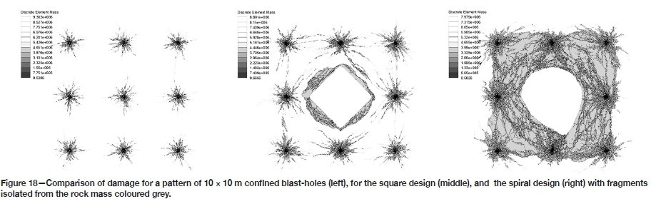
Figure 18 compares the limited damage accumulated in the rock mass for a confined preconditioning blast, with blast-holes on a 10 χ 10 m spacing with no interconnected fractures from neighbouring blast-holes, to the two designs firing to an initial 1.5 m diameter pilot hole. The regions coloured grey are fragments that have broken away from the rock mass, highlighting the significant increase in discrete fragments in the spiral design over the other two designs.
To the design aspects, the following comments can be added.
➤ High-sensitivity bulk explosive is preferred. Larger blast-hole diameters will improve detonation performance of the bulk product and produce more damage. Larger diameter holes also suffer less deviation. Simultaneous detonation of blast-holes will produce the best overall fragmentation.
➤ The primers should be detonated simultaneously in each hole.
➤ The recommended spacing between the booster charges is around 8 m.
➤ The primers in adjacent holes should be offset to produce a more even fracture network between blast-holes
Conclusions
There are no established design rules for preconditioning in caving mines. Therefore, evaluating different designs in different rock masses requires the use of sophisticated numerical modelling incorporating representative detonation performance, and the response of the rock mass to the explosive loading through a strain-rate-dependent material model, including failure.
The modelling in this study evaluated the blast performance based on the extent of the crush zone and crack zone around individual blast-holes. It can be concluded that due to the operational and technical requirements in preconditioning (length and diameter of the holes), under high stress conditions, a bulk emulsion rather than ANFO is the preferred explosive. In particular the emulsion produces a much larger crush zone compared to ANFO. When assessing the radial crack extension between two blast-holes the optimal hole spacing can be selected to maximize the crack length.
As regards the rock mass, it has been shown that the most critical factor is the in-situ stress state in the area where preconditioning is needed, with higher stresses significantly impeding the blast-induced fracture network. When there is stress anisotropy in the rock mass, greater fracture extension is produced in the direction of the major principal stress. The network of structures present in the rock mass can have a significant impact on the propagation of radial fractures and will disperse the blast-induced stress waves. The use of free faces will allow the possibility of directing the energy from the blast, providing a better efficiency, and reducing damage to the surrounding infrastructure.
If a combined preconditioning scheme is to be used (hydraulic fracturing together with dynamic debilitation with explosives), it is important to study and analyse the effect of the explosive in the HF-induced fractures. For a range of HF spacing (0.5 m, 1.0 m, and 1.5 m) the 1.5 m spacing was found to produce the largest total blast-induced fracture length, which was greater than the simulation with no HF.
Obtaining optimal fragmentation at the drawpoint through preconditioning is hindered by the predefined mining layout (spacing of production and crosscut drives), increased in-situ stresses, and a more competent rock mass in deeper mines, with the addition of confined low powder factor designs. Under all these restrictions, a blasting design is proposed that is based on what has been learned in blasting underground drawbells and the development of tunnels, where a partial free face is developed through a void hole created using mechanized drilling, and the appropriate blast-hole pattern and initiation sequence are designed to fire into the void, enlarging the void to maintain the relief through the blast.
Further developments in numerical modelling could include real mapped locations and conditions of the stack of hydro-fractures, rather than the idealized representation in this current modelling. A second challenge is quantifying the real effect on fragmentation due to the flow of the rock mass within the cave. This will provide information on the flow distance required to achieve the desired fragmentation, and thus an estimation of the height of the primary domain to be pre-conditioned, focusing the efforts on the first part of the primary domain where the coarser fragments are produced.
The application of numerical modelling in mining, allows the testing of different design options within a sensitivity analysis of rock mass conditions, identifying the options that show potential for successful implementation. Field data from the implemented options must then be collected to validate the models, so as to continue improving the preconditioning models.
References
Andrieux, P. and Hadjigeürgiqu, J. 2008. The destressability index methodology for the assessment of the likelihood of sucess of a large scale confined destress blast in an undergound pillar. International Journal of Rock Mechanics and Mining Sciences, vol. 45. pp. 407-421. [ Links ]
Aydan, 0. 2013. In situ stress inference from damage around blasted holes. Geosystem Engineering, vol. 16, no. 1. pp. 83-91. [ Links ]
BAez, F., Arancibia, Ε., Piñeyrq i., and León, J. 2014. Numerical analysis of preconditioning using blasting and its relationship with the geomechanical properties of the rock mass and its interaction with hydraulic fracturing. Proceedings of Caving 2014, Santiago, Chile. Castro, R. (ed.). Universidad de Chile, Sanatiago. pp. 538-546. [ Links ]
Blantqn, T.L. 1981. Effect of strain rates from 10-2/sec-10-1/sec on three rocks. International Journal of Rock Mechanics and Mining Sciences & Geomechanical. Abstracts, vol. 18. pp 47-62. [ Links ]
Brown, Ε. 2007. Block Caving Geomechanics. 2:1997-2004. JKMRC, Brisbane. [ Links ]
Brummer, R.K. and Andrieux, P.P. 2002. A design methodology for destress blasting. NARMS-TAC 2002: Mining and Tunnelling Innovation and Opportunity. Proceedings of the 5th North American Rock Mechanics Symposium and the 17th Tunnelling Association of Canada Conference, vol. 1. Hammah, R. ed.). University of Toronto Press. pp. 165-172. [ Links ]
Brzovic, a, Hurtado, J.P., and MarIn, N. Intensity rock mass preconditioning and fragmentation performance at the El Teniente Mine, Chile. Caving 2014 pp. 547-556 [ Links ]
Castro, C., BAez, F., Arancibia, Ε., and Barrera, V. Study of the impact of rock mass preconditioning on a block caving mine operation. Proceedings of Caving 2014, Santiago, Chile. Castro, R. (ed.). Universidad de Chile, Sanatiago. pp. 515-524. [ Links ]
Catalan A, Dunstan G, Morgan Μ, Green S, Jorquera S, and Thornhill T. 2012. "Intensive" preconditioning methodology developed for the Cadia East panel cave project, NSW, Australia. MassMin 2012. Proceedings of the 6th International Conference and Exhibition on Mass Mining, Sudbury, ON. Canadian Institute of Mining, Metallurgy and Petroleum, Montreal. Paper no 6819. [ Links ]
Catalan, Α., Onederra, I., and Chitombo, G. 2012. A proposed methodology for evaluation of the preconditioning by blasting at the Cadia East panel cave mine.MassMin 2012, Proceedings of the 6th International Confeernce on Mass Mining, Sudbury, ON, 10-14 June. Canadian Institute of Mining, Metallurgy and Petroleum, Montreal. Paper 6920. [ Links ]
Cerruti, C. 2009. Study on the seismic response of pre-conditioned rock masses. Report IM2 P 76/08-IP-003. Codelco, Santiago, Chile. [ Links ]
Cho, S.H., Otaga, y., and Kaneko, K. 2003. Strain-rate dependence of the dynamic tensile strength of rock. International Journal of Rock Mechanics and Mining Sciences & Geomechanical. Abstracts, vol. 40. pp 763-777. [ Links ]
Eadie, B.A. 2002 Modelling primary and secondary fragmentation for block caving, PhD thesis, University of Queensland, Brisbane. [ Links ]
Jung, W.J., Utagava, Μ., Ogata, y., Seto, Μ., Katsuyama, K., Miyake, Α., and Ogava, T. 2001. Effects of rock pressure on crack generation during tunnel blasting. Journal of Japan Explosives Society. vol. 62, no. 3. pp. 138-146. [ Links ]
Minchinton, Α. and Lynch, P.M. 1996. Fragmentation and heave modelling using a coupled discrete element gas code. Proceedings of the 5th. International Symposium on Rock Fragmentation by Blasting, Montreal, Canada, 25-29 August. A.A. Balkema, Rotterdam. pp. 71-80. [ Links ]
Onederra, I., Catalan, Α., and Chitombo, G. 2013. Modelling fracturing, disturbed and interaction zones around fully confined detonating charges. Mining Technology, vol. 122, no. 1. pp. 20-32. [ Links ]
Owen, D.R.J., Munjiza, Α., and Bicanic, N. 1992. A finite element-discrete element approach to the simulation of rock blasting problems. Proceedings of the 11th Symposium on Finite Elements in South Africa, Cape Town, 15-17 January. Centre for Research in Computational and Applied Mechanics, University of Cape Town. pp. 39-58. [ Links ]
Prasad, U. 2000. Dynamic fracture characteristics of selected rocks. PhD dissertation, Department of Mining and Metallurgical Engineering, McGill University, Montreal. [ Links ]
Saharan, M.R. 2004. Dynamic modelling of rock fracturing by destress blasting. PhD thesis,McGill University, Montreal. [ Links ]
Sougarret, J., Quiñones, L., Morales, R., and Apablaza, R. New Vision in Caving Mining in Andina Division, Codelco Chile. Mass Min 2004, Santiago Chile. 22-25 August 2004. p. 543. [ Links ]
Starzec, P. 1999. Dynamic elastic properties of crystalline rocks from south-west Sweden. International Journal of Rock Mechanics and Mining Sciences, vol. 36. pp 265-272. [ Links ]
Sudbury, ON, 10-14 June. Paper no, 6819.
Toper, A.Z. 2003. The effect of blasting on the rock mass for designing the most effective preconditioning blasts in deep level gold mines. PhD thesis, University of the Witwatersrand, Johannesburg. [ Links ] ♦
 Correspondence:
J.S. Contreras
Email: jscontreras@udd.cl
Received: 13 Jul. 2020
Revised: 19 Nov. 2020
Accepted: 1 Dec. 2020
Published: February 2021
ORCID: E. Córdovahttps://orchid.org/0000-0002-9187-4461
A. Anani https://orchid.org/0000-0001-9125-6877

