


Services on Demand
Article
 English (pdf)
 Article in xml format
 Article references
Indicators

Related links
-
 Cited by Google
 -
 Similars in Google
Share

 Permalink
Journal of the Southern African Institute of Mining and Metallurgy
On-line version ISSN 2411-9717
Print version ISSN 2225-6253
J. S. Afr. Inst. Min. Metall. vol.120 n.10 Johannesburg Oct. 2020
http://dx.doi.org/10.17159/2411-9717/1066/2020
PAPERS OF GENERAL INTEREST
Modelling the effect of blast-induced vibrations on the stability of a faulted mine slope
H. BazziI; H. NoferestiII; H. FarhadianII
IMaster of Science in Mining Engineering, Faculty of Engineering, University of Birjand, Birjand, Iran. https://orchid.org/0000-0003-2424-0394
IIAssistant professor of Mining Engineering, Faculty of Engineering, University of Birjand, Birjand, Iran. H. Farhadian: https://orchid.org/0000-0002-9948-0731
SYNOPSIS
Blasting, which is carried out regularly in open-pit mines, causes considerable ground vibration in the vicinity of the blasting site. These vibrations may affect the stability of mine slopes, causing problems in safety and constituting a hazard to life and property. In this study, the effect of the blasting-induced vibrations on slope stability was investigated using finite element (FE) analysis. A pit slope containing a fault was examined under seismic loading caused by successive explosions with varying intensity. Some reference points were selected above/under the fault surface and their motions recorded during the FE analysis. The results show that the points above the fault surface have the greatest displacement, while below the fault surface, only minimal (negligible) motions occur. Also, the intensity of the explosion has the greatest impact on motions at the upper points, but below the fault surface, the effect of the blast intensity was minimal. Usually, each explosion causes only small displacements in the mine slopes, but the destabilizing effect of repeated weekly blasts is significant, as confirmed in the present study. A sensitivity analysis proved a direct relationship between both the shear stiffness and friction angle of the fault surface and the motions of upper reference points. Likewise, in the presence of underground water pressure, the blasting-induced movements increase sharply.
Keywords: blasting, slope stability, finite element analysis, dynamic analysis.
Introduction
In surface mines, blasting is necessary for fragmenting of medium to hard rocks. However, there are side effects like ground vibration, air vibration, and fly rock that may cause damage to buildings and other structures in the vicinity of the mining site. In a blasting operation, around 20-30% of the explosive energy is spent on rock fragmentation, and the large remaining fraction is lost through ground vibration, fly rock, air vibration, noise, and back-break (Murmu, Maheshwari, and Verma, 2018).
Ground vibration is a major side effect of blasting operations, and special regulations are in place to minimize damage to nearby structures. These regulations depend mainly on the maximum particle velocity (Görgülü et al., 2013; Ozer et al., 2008; Azizabadi, Mansouri, and Fouché, 2014; Saadat, Khandelwal, and Monjezi, 2014). The US Bureau of Mines proposed the first rules for maximum particle velocity (Siskind et al., 1980). The legal constraints in ground vibration are related to the largest mass of explosive per delay and distance from the explosion site.
The impact of the explosion on civil structures has been well studied, and there are guidelines for the frequency of shaking, maximum charge mass, and the minimum distance to avoid any damage to buildings (Siskind et al., 1980; Singh and Roy 2010; Faramarzi, Farsangi, and Mansouri, 2014). However, no such precise guidelines exist to minimize the explosion damage on the mine slopes, which are much closer to the blasting location. This is mainly due to the complexity of rock masses, and the issue of the cyclic nature of loading on mine slopes by successive explosions.
In this study, the effect of repeated explosions in a regular mining operation on the stability of a typical mine slope is investigated using a dynamic analysis method.
The importance of the dynamic analysis of the mine slopes has been emphasised in various studies (Terzaghi 1950; Stewart, Blake, and Hollingsworth, 2003; Bray and Travasarou 2009; Clough and Chopra 1966; Jibson Harp, and Michael, 2000; Newmark 1965). Terzaghi (1950) did pioneering research on the effects of seismic motion on slope stability, and various methods for investigating slope stability under seismic loading have subsequently been proposed. The conventional techniques for slope stability analysis in seismic conditions include pseudo-static analysis (Terzaghi 1950), Newmark displacement analysis (Newmark 1965), and dynamic numerical analysis (Seed 1979; Finn et al., 1986).
Pseudo-static stability analysis is a widely used limit equilibrium method that replaces the effect of dynamic earthquake loads by a constant equivalent-static acceleration (Terzaghi 1950). Newmark displacement analysis is a straightforward method in which an estimation of the permanent deformation during an earthquake is made and then compared to what is regarded as acceptable deformation (Newmark 1965). For large mine slopes under complex seismic loading, the use of dynamic numerical analysis is recommended. This type of analysis is usually performed using the finite element or finite difference method (Roy, Dayal, and Jain, 2007). In this paper, using an acceleration-time wave typical of a mine blast, the effect of blast-induced vibrations on the stability of a faulted mine slope was investigated through a dynamic analysis with the finite element method.
Dynamic numerical analysis
Dynamic numerical analysis essentially involves estimation of the deformation behaviour of a geotechnical slope using the finite element or finite difference method (Roy, Dayal, and Jain, 2007). A meshing scheme is used to represent the deformation of a slope during a seismic event. In each node of the mesh, displacement values are estimated as the result of external loads applied to the model. Usually in two-dimensional models, triangular (three or six nodes) or quadrilateral (four or eight nodes) elements are used. In comparison with pseudo-static and Newmark methods, dynamic numerical analysis is an exact method, yet the accuracy of this approach depends on the type of elements, mesh quality, mesh design, and structure of model (Melo and Sharma 2004).
An advanced modelling procedure and high-quality input data are required to acquire reliable results from the dynamic numerical analysis. Using the dynamic numerical method, a detailed representation of slope behaviour during a seismic event is plausible. In this regard, a decision must be made about numerous parameters, with damping coefficient, dynamic boundaries, and deformation modulus of materials being the most critical.
Damping coefficient
A dynamic system constantly loses its kinetic energy to reach a static condition. The damping rate of the system determines the amount of energy loss per unit time. The damping rate of geotechnical systems is related to internal friction and slip along weak structural surfaces (Bargi, 2010). In practice, it is hard to determine the damping data for dynamic simulations, and if available, use of experimental data is very helpful. Rayleigh damping is a straightforward method to define the damping of vibrating systems, in which the damping of a system (C) relates to its mass (m) and stiffness (k):

where, amand βkare constants with units of s-1 and s respectively.
A system with several degrees of freedom has a large number of natural frequencies, but a constant level of damping is not possible for all frequencies because of the nature of the problem (Rocscience, 2020). If Rayleigh damping is applied, a damping ratio is set for two selected frequencies, and a damping predictor like the Lagomarsino model (Lagomarsino, 1993) is used to define the rest of the frequencies. With the Lagomarsino model, the frequencies between the two fixed frequencies hold a damping ratio less than the set value and frequencies outside this range are damped more heavily.
By selecting a damping ratio in two fixed frequencies, the alpha and beta values of Rayleigh damping can be calculated. Alternatively, the alpha and beta values may be determined directly. Setting the damping coefficients to zero corresponds to an undamped system, which results in the transient response of the system never dissipating (Rocscience Inc, 2019).
Dynamic boundaries
Realistic and fictitious boundaries are used in dynamic numerical analysis of geotechnical systems. Fictitious boundaries do not exist physically but are used to encapsulate infinite volumes. Using these boundaries in a dynamic analysis prevents the reflection of retreating waves and their return to the modelling domain. The main types of boundaries that are often used in dynamic models are absorbing, transmitting, damper, nodal mass, tied, and hydro mass.
Stability assessment of mining slope against a simulated blasting
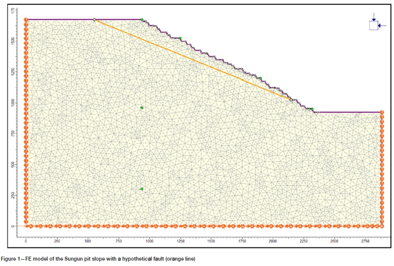
The southwestern final pit wall of Sungun copper mine with a hypothetical fault in it was modelled using RS2 software as shown in Figure 1. RS2 (formerly Phase2) is a 2D finite element program that can be used for a wide range of engineering projects, including advanced dynamic analysis of slopes. A wide array of material models is built in RS2. Additional new material models from well-known numerical tools like FLAC and PLAXIS are included. The RS2 program has been successfully applied to slope stability analysis (Hammah et al., 2009; Allan, Yacoub, and Curran, 2012; Noferesti and Hazegh, 2018). Results from RS2 models for slope stability analysis are verified against standard FLAC models (Rocscience Inc., 2020), UDEC models (Hammah et al., 2007), and limit equilibrium or analytical models (Hammah et al., 2005; Azami, Yacoub, and Curran, 2012).
A total of 1500 six-node triangular elements are present in this model. The Mohr-Coulomb strain-softening model was defined as the failure criterion of the medium. The fault boundary was assigned appropriate strength and stiffness characteristics to determine its response to stress. Elastic displacement and inelastic slip were allowed along the fault surface. The bottom and lateral sides of the slope model in Figure 1 are fictitious boundaries that attempt to simulate the infinite boundary effect of the earth medium. The lateral sides of the model were set as the transmit boundary that permits the incoming waves to enter the system while absorbing shear and pressure waves that would be moving out of the model domain. The bottom of the model was set as an absorb boundary type that absorbs the exiting wave from the system.
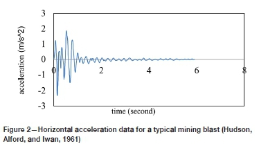
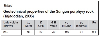
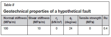
For dynamic analysis of a mining slope, an acceleration-time record of a blasting event is needed. In this study, an acceleration-time record presented by Hudson, Alford, and Iwan, (1961) has been used. As seen in Figure 2 this record lasts for 6 seconds, and its maximum absolute value is equal to 0.24 g. The blast position is situated in other areas of the mine so that the blast-holes do not intersect the fault surface. However, it is assumed the blasting event causes a vibration in the slope model, as shown in Figure 2. The input geotechnical parameters of the mine slope model are given in Tables I and II. Before performing a dynamic numerical analysis, the following three steps should be completed (Rocscience Inc, 2019):
Step 1: Deconvolution of the seismic input
Earthquake ground motions are usually provided in terms of Earth surface acceleration data. However, for an RS2 analysis, the seismic input must be applied in the form of velocity data to the base of the model rather than the Earth's surface. Therefore, 'deconvolution' of the given data is needed, such that once it is applied at the base of the model, it correctly simulates the ground motion.
The following steps are performed in deconvolution of the adopted acceleration-time history for a compliant base model:
1. Integration of the acceleration-time history by applying the acceleration-time history to the top of a one-dimensional column model and measuring the resulting velocity data at a query point on top of the column.
2. Obtained velocity data is divided by 2. For a compliant base model, the upward-propagating wave train should be used. The upward-propagating wave is 1/2 the outcrop motion (Mejia and Dawson, 2006).
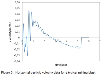
3. The halved velocity data, as shown in Figure 3, is converted to a stress wave and then applied to the base of the slope model.
Step 2: Filtering the input velocity of seismic loading
When modelling seismic loading, the numerical accuracy of wave transmission is determined by the frequency content of the input wave and the wave speed of the system. For the exact representation of wave transmission within a model, the spatial element size should be (Kuhlemeyer and Lysmer 1973):

where λis the wavelength related to the highest frequency portion that holds significant energy.
To satisfy Equation [2], an unusually fine mesh may be needed that may lead to an excessive amount of computing time. Fortunately, for most seismic events, the powerful part of the input velocity wave is carried in the lower-frequency portions (Rocscience Inc., 2019). By filtering the input wave and excluding high-frequency sections, a coarser mesh may be used without significantly influencing the results. The filter frequency for the adopted seismic event was selected as 4.5 Hz, and frequencies above this value were excluded from the dynamic analysis.
Step 3: Rayleigh damping
In the present study, the Rayleigh coefficients were defined explicitly as alpha = 0.5 and beta = 0.0036.
After completing the above steps, a dynamic analysis was conducted on the mining slope using the acceleration data of the assumed blast. Results are presented in the following sections:
Effect of number of explosions
The volume of minerals extracted in large surface mines is very high. So, usually, one blast per week is done in these mines. The ground vibration due to each blast increases the likelihood of instability of the surrounding mine slopes. Identifying the main rock fractures and studying the blocks formed by these discontinuities is very important in the investigation of the stability of the mine slopes.
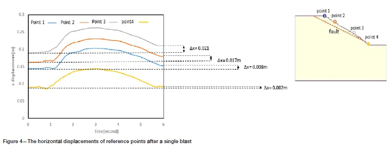
The FE model of the mining slope was analysed under the loading effect of a single blast. Figure 4 shows the motion of four points on the mine slope during the loading process of a single blast, which lasts for 6 seconds. The point designated 4, located below the fault position, experienced the least effect from the blast while three other points, located over the fault, show considerable movement. Point 3, which is the closest point to the fault surface, shows the most displacement. The significant difference between the motion of points 4 and 3 confirms the severe effect of blasting on fault movement.
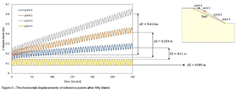
While the destabilizing effect of a single blast is negligible, the impact of repeated weekly blasts may be considerable. Figure 5 shows the motion of points 1 to 4 on the same mine slope after 50 blasts, an estimate for one year of mining. By comparing the motion values of reference points between two states (i.e., single and fifty blasts) interesting results are obtained. Point 4 in both cases shows negligible movement, which implies that single or repeated blasts in mining operations do not have much effect on massive intact slopes. Points 1 to 3, however, exhibited a large progressive movement towards the pit after 50 blasts. This indicates that in real mining situations a fault under repeated blasts may finally become unstable and a large slope failures occur.
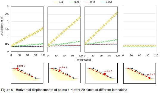
Impact of blast intensity
The effect of blast intensity on mine slope model was studied by scaling up and down the horizontal acceleration data of Figure 2. The original acceleration wave of Figure 2 was scaled to the degree that the maximum acceleration reached to 0.05 g, 0.1 g, 0.2 g, and 0.5 g in each case. Figure 6 shows the motion of points 1 to 4 after 20 blasts of different intensities. Point 4 again shows no movement, even for the strongest blasts, but in the case of points 1 to 3, which lie over the fault, the displacement values increase monotonically with the blast intensity.
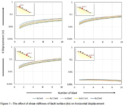
Impact of fault surface stiffness
Fault surface stiffness is a critical parameter, affecting fault behaviour under static/dynamic loading conditions, and is defined in two directions, i.e., normal and parallel to the fault surface. The shear (parallel) stiffness of the fault surface (ks) was changed from 0.5 MPa/m to 1.5 MPa/m and displacement of reference points was recorded after ten blasts. In the FE model the normal stiffness of the fault (kn) was considered to be considered ten times the shear stiffness. The maximum movement for reference points (Figure 7) was observed in the case of the least shear stiffness.
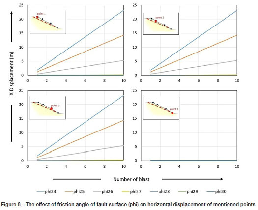
Impact of friction angle of fault surface
The friction angle of fault surface was reduced gradually from 30° to 24° and the displacement of the reference points recorded after ten blasts. When the friction angle was reduced to 26° a sudden increase in the motion of the reference points was observed, except for point 4 (Figure 8). Further reduction of friction angle in the FE model resulted in extraordinarily large displacement values for points 1 to 3. On the other hand, for friction angle values of 27° and larger, insignificant movement of points located above the fault surface was observed after ten blasts (Figure 8). This implies that in surface mining operations for any given fault there is a critical friction angle, below which failure can be expected after repeated blasting.
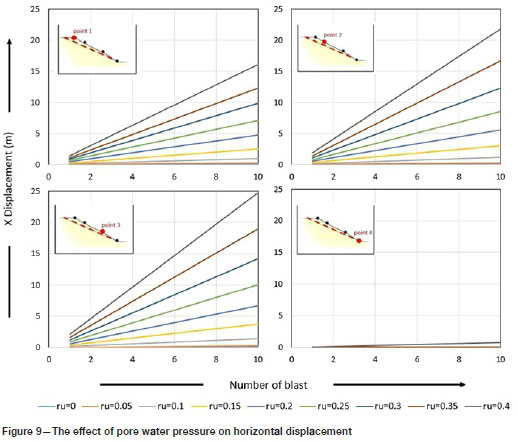
Impact of pore water pressure
The ratio of pore water pressure to overburden pressure, Ru, was changed from 0 to 0.4 in the FE models and displacements of reference points recorded after ten blasts. In all cases, points 1 to 3 indicated a continuous increase in motion as greater Ru values were applied to the mine slope models (Figure 9). For Ru values < 0.35 point 4 was almost stable and indicated minimal motion change, but for Ru = 0.4 a sudden large motion was observed as the seismic load was applied to the model. It seems that a Ru value between 0.35 and 0.4 is the critical value above which the intact rocks in the mine slope collapse under blast loading.
Conclusions
In the FE model of a mine slope under the seismic effects of a mining blast, the largest motions were observed for the reference points above the fault surface, and below the fault surface only negligible movement was detected. A stronger blast caused higher displacements in the mine slope, especially in the presence of a fault, the points' motions increased remarkably.
The shear stiffness of the fault surface is another factor affecting the behaviour of a mine slope close to a blasting event. Increasing the shear stiffness of the fault decreased the displacements, but with repeated blasts a sudden increase of movement was observed at first, but then the rate of increase slowed.
Reducing the friction angle of the fault surface significantly increased the amount of displacement, so that at a lower friction angle the mine slope became unstable. Investigation of the effect of pore pressure showed that the points above the fault surface underwent higher displacements as pore pressure increased. At Ru = 0.25, the fault surface showed large movements, and the mine slope collapsed.
Although each blast causes small displacements in the mine slope, with repeated blasts the movements will gradually become significant, which may lead to slope failure. When deciding on an blasting pattern, the amount of explosive per delay should be selected with great care so that the explosion-induced shock wave does not cause permanent displacement in the mine slopes. Even so, the effect of repeated blasts on the movement of the mine slopes should not be forgotten. A detailed numerical study, similar to the present one, is required in each case.
References
Allan, F.C., Yacöüb, T.E., and Curran, J.H. 2012. On using spatial methods for heterogeneous slope stability analysis. Proceedings of the 46th US Rock Mechanics/ Geomechanics Symposium, Chicago, IL, 24-27 June 2012. American Rock Mechanics Association, Alexandria, VA. [ Links ]
Azami a., Yacoub T.E., and Curran J.E. 2012. Effects of strength anisotropy on the stability of slopes. Proceedings of the 65th Canadian Geotechnical Conference, Winnipeg, Manitoba, 30 September - 3 October 2012. https://www.rocscience.com/assets/resources/learning/papers/Effects-of-Strength-Anisotropy-on-the-Stability-Analysis-of-Slopes.pdf [ Links ]
Azizabadi, H.R.M., Mansouri, H., and Fouché, O. 2014. Coupling of two methods, waveform superposition and numerical, to model blast vibration effect on slope stability in jointed rock masses. Computers and Geotechnics, vol. 61. pp. 42-49. [ Links ]
Bargi, K. 2010. Fundamentals of Earthquake Engineering. Tehran University Press, Tehran. [ Links ]
Bray, J.D. and Travasarou, t. 2009. Pseudostatic coefficient for use in simplified seismic slope stability evaluation. Journal of Geotechnical and Geoenvironmental Engineering, vol. 135. no. 9. pp. 1336-1340. [ Links ]
Clough, R.W. and Chopra, A.K. 1966. Earthquake stress analysis in earth dams. Journal of the Engineering Mechanics Division, ASCE, vol. 92, no. 2. pp.197-212. [ Links ]
Faramarzi, F., Farsangi, M.A.E., and Mansouri, H. 2014. Simultaneous investigation of blast induced ground vibration and air blast effects on safety level of structures and human in surface blasting. International Journal of Mining Science and Technology, vol. 24. no. 5. pp. 663-669. [ Links ]
Finn, W.D.L., Yogendra Kumar, M., Yoshida, N., and Yoshida, H. 1986. TARA-3: A Program for Nonlinear Static and Dynamic Effective Stress Analysis, Department of Civil Engineering, University of British Columbia, Vancouver, British Columbia, Canada. [ Links ]
Gôrgülü, K., Arpaz, E., Demirci, A., Koçaslan, A., Dilmaç, M.K., and Yüksek, A.G. 2013. Investigation of blast-induced ground vibrations in the Tülü boron open pit mine. Bulletin of Engineering Geology and the Environment, vol. 72. no. 3-4. pp. 555-564. [ Links ]
Hammah, R.E, Yacoub, TE., Corkum, B., and Curran, J.E. 2005. The shear strength reduction method for the generalized Hoek-Brown criterion. Proceedings of the 40th US Symposium on Rock Mechanics (USRMS): Rock Mechanics for Energy, Mineral and Infrastructure Development in the Northern Regions, Anchorage, Alaska, 25-29 June 2005. American Rock Mechanics Association, Alexandria, VA. [ Links ]
Hammah, R.E, Yacoub, Te., Corkum, B., wibowo, F., and Curran, J.E. 2007. Analysis of blocky rock slopes with finite element shear strength reduction analysis. doi: 10.1201/NOE0415444019-c40 [ Links ]
Hammah, R.E, Yacoub, Te., and Curran J.E. 2009. Probabilistic slope analysis with the finite element method. Proceedings of the 43rd US Rock Mechanics Symposium and 4th US-Canada Rock Mechanics Symposium, Asheville, NC, 28th June- 1. July 2009. American Rock Mechanics Association, Alexandria, VA. [ Links ]
Hudson, D.E., Alford, J.L., and Iwan, W.D. 1961. Ground accelerations caused by large quarry blasts. Bulletin of the Seismological Society of America, vol. 51. no. 2. pp. 191-202. [ Links ]
Jibson, R.W., Harp, E.L., and Michael, J.A. 2000. A method for producing digital probabilistic seismic landslide hazard maps. Engineering Geology, vol. 58. no. 3-4. pp. 271-289. [ Links ]
Kuhlemeyer, R.L. and Lysmer, J. 1973. Finite element method accuracy for wave propagation problems. Journal of Soil Mechanics & Foundations, vol. 99, no. 5. pp. 42-427. [ Links ]
Lagomarsino, S. 1993. Forecast models for damping and vibration periods of building. Journal of Wind Engineering and Industrial Aerodynamics, vol. 48. pp. 211-239. [ Links ]
Mejia, L.H. and Dawson, E.M. 2006. Earthquake deconvolution for FLAC. Proceedings of the 4th International FLAC Symposium on Numerical Modeling in Geomechanics, Hart, R. and Varona, P. (eds.) Itasca Consulting Group, Inc., Minneapolis, MN. Paper 04-10. http://www.zamiran.net/uploads/3/7/2/1/37218831/mejia_and_dawson_paper.pdf [ Links ]
Melo, C. and Sharma, S. 2004. Seismic coefficients for pseudo-static slope analysis. Proceedings of the 13th World Conference on Earthquake Engineering, Vancouver, Canada. Canadian Association for Earthquake Engineering. https://www.iitk.ac.in/nicee/wcee/article/13_369.pdf [ Links ]
Murmu, S., Maheshwari, P., and verma, H.K. 2018. Empirical and probabilistic analysis of blast-induced ground vibrations. International Journal of Rock Mechanics and Mining Sciences, vol. 103. pp. 267-274. [ Links ]
Newmark, N.M. 1965. Effects of earthquakes on dams and embankments. Geotechnique, vol. 15. no. 2. pp. 139-160. [ Links ]
Noferesti, H. and Hazegh, A. 2018. Comparison of pseudo-static, Newmark and dynamic response analysis of the final pit wall of Sungun copper mine. International Journal of Mining & Geo-Engineering, vol. 52, no. 2. pp. 141-147. [ Links ]
Ozer, u., Kahriman, A., Aksoy, M., Adiguzel, D., and Karadogan, A. 2008. The analysis of ground vibrations induced by bench blasting at Akyol quarry and practical blasting charts. Environmental Geology, vol. 54. no. 4. pp. 737-743. [ Links ]
Rocscience Inc. 2020. RS 2 online help, Dynamic analysis. https://www.rocscience.com/help/rs2/webhelp9/RS2.htm [ Links ]
Rocscience Inc. 2020. RS 2 online help, Dynamic module verification manual. https://www.rocscience.com/help/rs2/pdf_files/verification/RS2_Dynamics_Verification.pdf [ Links ]
Roy, D., Dayal, u., and Jain, S.K. 2007. IITK- GSDMA Guidelines for seismic design of earth dams and embankments, provision with commentary and explanatory examples. Indian Institute of Technology, Kanpur, India. [ Links ]
Saadat, M., Khandelwal, M., and Monjezi, M. 2014. An ANN-based approach to predict blast-induced ground vibration of Gol-E-Gohar iron ore mine, Iran. Journal of Rock Mechanics and Geotechnical Engineering, vol. 6. no. 1. pp. 67-76. [ Links ]
Seed, H.B. 1979. Considerations in the earthquake resistant design of earth and rockfill dams. Geotechnique, vol. 29. no. 3. pp. 215-263. [ Links ]
Singh, P.K. and Roy, M.P. 2010. Damage to surface structures due to blast vibration. International Journal of Rock Mechanics and Mining Sciences, vol. 47. no. 6. pp. 949-961. [ Links ]
Siskind, D.E., Stagg, M.S., Kopp, J.W., and Dowding, C.H. 1980. Structural response and damage produced by ground vibrations from surface mines blasting. Report of Investigation 8507. US Bureau of Mines [ Links ]
Stewart, J.P., Blake, T.F., and Hollingsworth, R.A. 2003. A screen analysis procedure for seismic slope stability. Earthquake Spectra, vol. 19. no. 3. pp. 697-712. [ Links ]
Tajadodian F.R. 2005. Slope stability studies for Sungun Copper Mine, Pars Olang Consulting Engineers, Tehran, Iran. [ Links ]
Terzaghi, K. 1950. Mechanism of landslides, Application of geology to engineering practice. Geotechnical Society of America, Berkeley, pp. 83-123. [ Links ]
 Correspondence:
H. Noferesti
Email: hnoferesty@birjand.ac.ir
Received: 11 Dec. 2019
Revised: 24 Aug. 2020
Accepted: 7 Sep. 2020
Published: October 2020

