


Serviços Personalizados
Artigo
 Inglês (pdf)
 Artigo em XML
 Referências do artigo
Indicadores

Links relacionados
-
 Citado por Google
 -
 Similares em Google
Compartilhar

 Permalink
Journal of the Southern African Institute of Mining and Metallurgy
versão On-line ISSN 2411-9717
versão impressa ISSN 2225-6253
J. S. Afr. Inst. Min. Metall. vol.120 no.7 Johannesburg Jul. 2020
http://dx.doi.org/10.17159/2411-9717/1185/2020
TAILINGS PAPER
http://dx.doi.org/10.17159/2411-9717/1185/2020
Design of a lined platinum tailings storage facility in South Africa
L.H. Spies
SRK Consulting, Johannesburg, South Africa. https://orchid.org/0000-0001-7549-0882
SYNOPSIS
Under current environmental legislation in South Africa, tailings are viewed as potentially hazardous waste that needs to be disposed of in compliance with the appropriate minimum requirements. The platinum tailings in this case study were classified as a hazardous waste, requiring a geomembrane as a key component of the pollution control barrier for disposal. Traditionally, tailings dams in South Africa have been built on top of the in-situ soils. The use of composite liners is relatively new in tailings dam construction in South Africa and brings with it its own set of challenges.
FOR EXAMPLE: where before the natural drainage through the in-situ soils aided drainage of the tailings dam, all drainage must now take place through engineered systems, stability of the tailings dam needs to be assessed considering potential weak planes caused by the barrier system, and management of stormwater during construction must be carefully planned. This paper presents a case study highlighting how some of these challenges were addressed in a project where a composite liner was included in the design of the tailings dam
Keywords: tailings storage facility, barrier system, composite liner, geomembrane.
Introduction
The requirement for a barrier system in South Africa
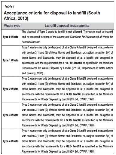
The regulations promulgated under the National Environmental Management Act - Regulations 632, 634, 635 and 636 (South Africa, 2013) - are currently administered by the Department of Water and Sanitation (DWS) in South Africa. Under these regulations waste, including tailings, is assessed under Waste Acceptance Criteria for Disposal to Landfill (refer to Table I), which determines the requirements for disposal of different types of waste. Under these regulations, many mineral residue deposits are found to require a barrier system, which typically includes a geomembrane. It is usually not practical, and currently not mandatory, to retrofit a barrier system to existing tailings dams. However, there is an increase in the number of new tailings dams being constructed to include a barrier system.
The Department of Water and Sanitation (DWS) no longer condones South Africa's philosophy of the past 20 years, in terms of which dilution of water contamination and dispersion relying on attenuation was regarded as acceptable (Legge, 2019). Protection of water resources, and prevention of contamination in the first place (source) is now being sought in preference to mitigating contamination spread (pathway) and pollution cleanup (receptor).
Apart from preventing polluted leachate from seeping into the groundwater, an additional benefit of lining a tailings dam is that more water in the tailings system can be captured and returned to the plant. This is useful in a water-scarce country such as South Africa. It is estimated that the addition of the composite liner in this case study will improve the water recovery of the tailings dam by 95 litres per ton of dry tailings deposited.
Since the tailings industry has not always included barrier systems in design or construction, there are learnings to be acquired, even by seasoned tailings consultants and contractors, on how to work with these systems.
A proposed amendment to Regulation 632 (2016) has been drafted whereby there could in future be a relaxation of the regulations on a case-by-case basis, following a risk-based approach. However, such regulations have yet to be promulgated into law. In the meantime, the current regulations apply to the disposal of tailings in the same way they apply to the disposal of any other waste to landfill.
Case Study - Manila tailings dam
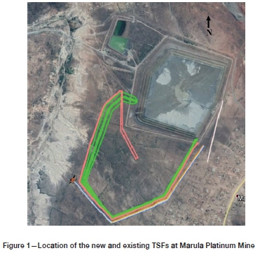
Marula Platinum Mine is located approximately 32 km northwest of the town of Burgersfort in Limpopo Province, South Africa. The pre-deposition works for the mine's existing tailings dam was constructed in 2003 as an unlined facility, in line with the legal requirements at that time. The existing tailings dam is approaching its end of life and a new tailings storage facility (TSF) is currently under construction to accommodate the mine's future tailings production. The footprint of the new TSF (77 ha) is shown in Figure 1 in relation to the location of the existing facility. The new TSF is planned to abut the existing facility and rise over the southern portion of the existing facility by some 5 m, to a maximum height of 47 m. The design life of the new TSF is 20 years.
The site for the new TSF slopes gently, at an approximate slope of 1:60, downwards toward the northwest. The geology of the site comprises part of the eastern limb of the Bushveld Complex (BC). Typically, the top 1.5 m of the soil profile consists of topsoil and firm to stiff clay (residual norite, also known as 'black turf'). Beneath this, soft rock (gabbronorite) is encountered. The Moopetsi River is located approximately 500 m to the west of the new facility.
The new TSF is designed to accommodate the full tailings stream from the Marula plant, so that operation of the facility is independent of any disposal requirements on the existing tailings dam. Since the new TSF will receive tailings from the same source as the existing tailings dam, its design is based on material properties derived from in-situ and laboratory testing of the tailings on the existing tailings dam. The design boundary conditions have been kept similar to those for the existing tailings dam, such as a maximum rate of rise (RoR) of 2.5 m/a.
Various studies have shown that the Marula tailings classifies as Type 3 waste according to Regulation 635 (2013). This is mainly due to the tailings leachate having elevated nitrate (N03) levels, in excess of the minimum leachable concentration threshold (LCT), for which no barrier system would have been required. It is understood that much of the nitrates result from the explosives used in the mining process.
Scavenger wells have been implemented around the existing tailings dam to limit the migration of the pollution plume into the groundwater. However, the DWS no longer views interception as acceptable where prevention in the first instance is possible.
According to Regulation 636, a Class C landfill barrier system, or a barrier of equivalent performance, is required for disposal of Type 3 waste. Thus, the new TSF will require a Class C barrier system or equivalent at its base. The components which make up a Class C barrier system are shown in Figure 2. Notably the system comprises:
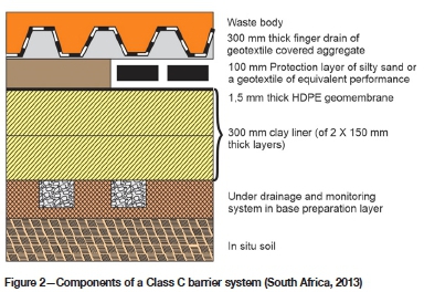
> Barrier components - a 1.5 mm thick HDPE geomembrane over a 300 mm thick clay liner (together referred to as the 'composite liner')
> Protection components - geotextile or fine material to preserve the integrity of barrier components
> Drainage above and below the barrier components.
The inclusion of a barrier system not only increases the complexity of the TSF design, but also its construction and operation. Various unique challenges had to be dealt with in this project; however, this paper focuses only on those specifically relating to the introduction of a barrier system into the design.
Design challenges
Drainage considerations
As soon as a low-permeability barrier system is introduced as part of a TSF, drainage needs to be carefully considered both above and below the barrier components. The drains significantly increase the already high cost of including a composite liner in the design.
The purpose of the above-liner drains is to:
> Draw down the phreatic surface (loosely equivalent to the water table) for structural stability purposes
> Reduce the head on the composite liner, thus reducing the seepage gradient
> Reduce the liquefaction potential of the tailings material. The purpose of the underliner drains is to:
> Mitigate against construction issues related to water trapped beneath the geomembrane forming 'whales', softening the foundations etc.
> Provide a leakage detection layer
> In this particular case, because the new TSF abuts the existing tailings dam, to drain seepage from the existing facility.
Drains need to be designed with protection from stormwater damage in mind (e.g. to protect against erosion of filter material or flow of runoff beneath a partially completed liner). Above-liner drains also need to be designed so that the fine tailings that are first deposited over them do not cause them to blind, which would render them useless for the remainder of the facility's life.
Drainage design
Various alternatives were considered for the drainage above and below the composite liner. The final drainage design, presented to and accepted by the DWS, consisted of a herringbone structure of drains on a 50 m spacing, as shown in Figure 3. Steady-state finite element seepage modelling confirmed that this spacing reduces the head on the composite liner to 5 m for the worst case. This reduces the seepage gradient and hence possible seepage across the composite liner.
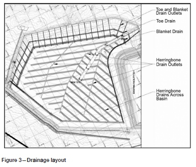
A robust toe and blanket drain were included in this above-liner drainage, designed with consideration of the closed form solutions and other recommendations presented by van Zyl and Robertson (1980). These are the primary drains responsible for drawing down the phreatic surface under the outer slope, which is required for structural stability. The outlets from the blanket and toe drains are separate from the rest of the basin drainage, also on a 50 m spacing. This means that in a worst-case scenario, if some of the inner basin drains were to block, the blanket and toe drains could continue to operate independently.
The herringbone drains across the basin of the TSF collect into three major arterials, which serve as outlets to these drains. The herringbone drains, in addition to reducing the head on the composite liner as already mentioned, attempt to mimic the basal drainage observed through piezocone test work on the existing tailings dam. In the existing tailings dam, downwards seepage in the tailings basin can flow, to a limited extent, into the in-situ soils, which act as a natural drainage medium for the flows. In the lined TSF, artificial drains that will permit equivalent flows need to be added.
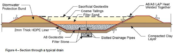
A section through a typical drain is shown in Figure 4. There are 0.5 m high bunds, covered with geomembrane, on both sides of the drain, to protect the drain from stormwater damage. Sacrificial geotextile, which is removed before deposition, temporarily covers the drain as an additional protection measure against stormwater damage. It is accepted that this geotextile will degrade to some degree due to UV exposure, and to this end an additional thickness of coarse tailings is included into the topmost layer of the drain. The coarse tailings also serve to prevent the sand filter layer of the drain from blinding should the finest tailings material be deposited directly over it. A substantial geotextile (A8) is included in the drains between the lowest gravel filter layer and the geomembrane. This is to protect the geomembrane from puncture by the gravel, and to limit strains in the geomembrane which would otherwise contribute to service life reduction (Brachman and Gudina, 2008).
To cater for uncertainties regarding how all the drains will perform, redundancy has been introduced in the number of pipes in the drains. This redundancy comes at a relatively minor cost compared to the major reassurance it brings.
Barrier component design
During the conceptual phase, alternatives to the composite liner were considered, ranging from a 7.4 m thick clay-only liner to vast amounts of drainage material only without a liner. Eventually a 2 mm thick HDPE geomembrane was selected, overlying a 300 mm thick compacted layer of clay. The geomembrane is thicker than that stipulated for a Class C landfill (1.5 mm), but it was chosen as it would be more resistant to damage during installation, and until it was covered everywhere with a protective layer of tailings. A double-sided textured geomembrane was chosen beneath the crest of the tailings dam to improve the interface friction between the geomembrane and the underlying clay/ overlying tailings. A smooth geomembrane was chosen for the much larger basin area of the tailings dam.
Stability
The stability of a TSF is commonly determined using limit equilibrium methods. The facility and its underlying soil horizons are considered as one 'combined structure' when undertaking slope stability analysis. The combined structure was designed to meet the factors of safety (FoS) listed in Table II for the various loading conditions, against large-scale slope failure.
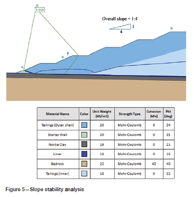
If there are significantly weaker layers within the TSF or its underlying soil horizons, the failure slip circle will generally pass through these weaker layers. In the case of the existing unlined facility, the black turf horizon presents a weak layer with a friction angle 0 = 21°. In the case of the new lined facility, the weakest layer is the interface of the soils/tailings with the geomembrane. The friction angle of this interface, as established from the literature, was taken as 0 = 16°. Specific shear interface testing between samples of the actual materials from site and the actual chosen geomembranes was undertaken. This confirmed that the design interface friction value of 16° was acceptable for both the smooth and textured geomembranes. Figure 5 shows the output of a slope stability analysis undertaken for one of the sections of the new TSF for loading condition 1, as defined in Table II. An overall outer slope of 1:4 is required to achieve the FoS design criteria. This is flatter than the slope of 1:3 that is used in the existing facility. The flatter slope means a reduction in the airspace available for material storage within the sloped areas of the lined TSF compared to the unlined tailings dam.
The design does not rely on stability berms to act as shear keys in order to meet the FoS design criteria. However, the drains are bunded (refer to Figure 4) which will to some extent act as stability berms and improve the geomembrane's resistance to interface shearing.
The phreatic surface for the slope stability analysis was based on the output of the seepage analysis discussed in the section on drainage design. In Figure 5 the assessment has assumed that all the drains are fully functional (loading condition 1). Stability analyses were also undertaken for the hypothetical scenario where the blanket drain is blocked and non-functional (loading conditions 3 and 4). This is considered a short-term, unsteady-state condition, which could be rectified through remedial measures and consequently a lower FoS is considered acceptable for this condition.
The geometry (width) of the coarser, more permeable tailings (outer desaturated zone) is known for the existing tailings dam from the results of piezocone test work. By ensuring that the boundary conditions for the existing and new facilities are as similar as possible, knowledge of the tailings behaviour (e.g. width of the outer desaturated zone) on the existing tailings dam can be extrapolated to the new TSF.
Paddocks
It is common practice for unlined, upstream constructed tailings dams to include paddocks at their toes to help manage stormwater runoff from the dam's outer slopes. The catchment paddocks are designed to contain and store the stormwater runoff for later evaporation or seepage into the in-situ soils. Stormwater that runs off the outer tailings slopes is considered contaminated water which, if allowed to seep into the in-situ soils, would defeat the purpose of lining the dam in the first place. The approach taken for this project was to combine the attenuation function of the catchment paddocks and the conveyance function of the solution trench into one system of inline attenuation ponds (Janse van Rensburg, 2018). The solution trench was designed to accommodate not only the base seepage flow, but also the peak storm flows from the outer tailings slopes.
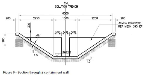
To avoid an excessively large solution trench channel area, containment walls were introduced every 100 m along the solution trench to slow the time it took for all the water from upper catchments to join the downstream flows in the solution trench. Base flow is catered for by a slit in the wall, while peak flow will build up and overtop the wall. A typical section through a containment wall in the solution trench is shown in Figure 6.
Construction challenges
Quality assurance
The success of a lined facility in acting to limit the seepage of leachate relies on all components of the barrier system being constructed to the highest standard. The geomembrane is manufactured to high quality standards, micrometre accuracy, and passed through numerous tests (in accordance with GRI-GM13, 2013) before even leaving the factory. Once construction starts, all of this effort can be lost if the same diligence is not applied during installation of the geomembrane.
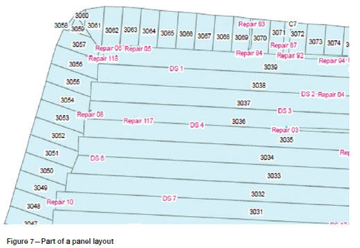
Each roll of geomembrane that arrives on site is accompanied by its a own quality certificate, so that if later there is a problem during the site inspections, it can be traced to a particular production batch at the factory. A panel layout is generated for the deployment of the geomembrane panels. An example of part of such a panel layout is shown in Figure 7. Each position in the layout is numbered so that which corresponding roll of geomembrane is in which position can be recorded. Many kilometres of welded seams between the panels need to be inspected, tested, repaired (if necessary), and records kept relating back to the panel layout. Such onerous quality assurance requirements during construction require a trained and meticulous workforce of quality inspectors.
Protection against stormwater damage
The timing for the construction of this project is such that a large portion of the drain construction and geomembrane installation will be done during the rainy season. Stormwater can flow very rapidly over the geomembrane, as it does not have the roughness of the natural vegetation. Stormwater can pond on top of the geomembrane, as it cannot infiltrate into the natural soils. High-speed stormwater flows and ponding of water can cause significant damage to the above-liner drainage.
In addition to the drain-specific measures that have been taken to protect the drains from stormwater damage (see section on drainage design), other measures have also been implemented. A permanent stormwater cut-off trench is included on the upslope eastern and southern sides of the facility. It is likely that temporary cut-off trenches may be needed upslope of sections of the basin to protect the barrier system during construction. Intermediate penstocks have been included in the design, close to the inner toe of the tailings dam, to assist with decant of ponding stormwater during construction.
Phasing and sequencing of construction
Phased construction of the new tailings dam was considered. Apart from the usual benefits associated with phased construction, such as delaying capital expenditure, in the case of a composite-lined facility there would be additional benefit in that the geomembrane would lie exposed to the elements and to vandalism for a shorter period before a protective layer of tailings is deposited. Closer consideration showed, however, that in the case of the new Marula TSF, because the site is relatively flat, the entire facility could be covered by a relatively thin layer of protective tailings within the first few years. Phasing was therefore not considered beneficial for this project.
The sequencing of construction works around the installation of a barrier system is complex but important. Once the geomembrane has been laid, traffic cannot be allowed to pass over it, as this can damage the geomembrane. Even pedestrian traffic must be limited, and labourers alerted to the fact that simply dropping a cigarette or a pen-knife onto the geomembrane can have serious consequences. With the herringbone drains spaced every 50 m, the geomembrane has to be laid concurrently with construction of the drains. The geomembrane cannot be trafficked over again in order to place the drainage materials over it.
The geomembrane cannot all be laid at once. Placement of the geomembrane will depend on the rate of drain construction. The contractor either has to order shipments of geomembrane in batches, which increases the risk that materials are not available on site when they are required, or has to store a vast quantity of geomembraneon site for a long time. The total time required for laying the geomembrane for the Marula TSF is approximately 9 months.
Geomembrane can deteriorate if stored for a long time exposed to the elements. Rolls of black geomembrane can heat up if ventilation is not allowed through stacks of the material. The upper exposed surface of a geomembrane was recorded to heat up to 83-86°C at midday at various sites in Limpopo (Legge, 2019). If covered with a thin (100 mm) layer of soil or tailings, the temperature of the geomembrane and number of associated wrinkles was found to reduce significantly. Placing a layer of tailings over the Marula TSF's geomembrane as soon as practical will be a priority.
Commissioning challenges
The project is not yet at the commissioning phase. The following areas will require careful attention when this phase is reached:
> Protection of drains from blinding. This is a challenge when commissioning any TSF. In the case of a TSF with a barrier system there are many more drains that need to be protected, so this activity needs to be much more rigorous.
> Removal of the sacrificial geotextile covering every drain before depositing over it. The geotextile has not been designed as a filter layer, but is in place to protect the other filter layers from eroding.
Conclusions
Barrier systems are a legislative requirement for many new tailings storage facilities in South Africa to protect surface and groundwater. Barrier systems also offer an opportunity to capture more water within the tailings system and return this water to the plant, which is useful in a water-scarce country.
Since the tailings industry has not always included barrier systems in its design or construction projects, there are many learnings still to be made, even by seasoned tailings consultants and contractors. There is a scarcity of as-built examples of tailings facilities constructed on composite liners, particularly in South Africa, so there are still unknowns relating to how these structures will behave in future. Stability and drain performance will need to be monitored rigorously during operation to confirm that these are performing as intended.
The inclusion of a barrier system into a tailings facility increases the complexity of not only the design, but also of construction and operation. This increased complexity comes with an associated increase in costs. These factors have been illustrated through the case study presented in this paper.
Acknowledgments
The sharing of site-specific data provided as part of this paper was made possible by Marula Platinum Mine. The author would like to thank all affiliated parties and all SRK colleagues forming part of the team involved in the design and construction phases of the new Marula tailings dam.
References
Brachman, R.W.I. and Güdina, S. 2008. Gravel contacts and geomembrane strains for a GM/CCL composite liner. Journal of Geotextiles and Geomembranes, vol. 26. pp. 448-459. [ Links ]
Geosynthetic Research Institute (GRI). 2013. GM13 standard specification for test methods, test properties and testing frequency for high density polyethylene (HDPE) smooth and textured geomembranes, revision 14. Folsom, PA. https://geosynthetic-institute.org/grispecs/gm13.pdf [ Links ]
Janse van Rensbürg, P. 2018. Case study of in-line attenuation ponds - Impact of changes in water policy, Proceedings of the Tailings and Mine Waste Conference 2018, Keystone, CO. Colorado State University. [ Links ]
Legge, K.R. 2019. An economy and ecosystem symbiosis: barrier systems for water conservation and pollution control. Proceedings of the 22nd International Conference on Paste, Thickened and Filtered Tailings, Cape Town, 8-10 May 2019. Australian Centre for Geomechanics, Perth. https://doi.org/10.36487/ACG_rep/1910_0.02_Legge [ Links ]
South Africa. 2013. National Environmental Management: Waste Act of 2008. Government Gazette, vol. 378, no. 36784, 23 August 2013. Regulation 636, Standard Containment Barrier Design, Waste Acceptance and Waste Disposal Requirements. [ Links ]
Van Zyl, D. and Robertson, A. 1980. Subsurface drainage of tailings impoundments: Some design, construction and management considerations. Proceedings of the Symposium on Uranium Mill Tailings Management. Colorado State University. pp. 153-177. https://pdfs.semanticscholar.org/8549/67f304976592dfc855bc918d166c5f9424f6.pdf [ Links ]
 Correspondence:
L.H. Spies
Email:lspies@srk.co.za
Received: 17 Apr. 2020
Revised: 22 Jun. 2020
Accepted: 22 Jun. 2020
Published: July 2020
This paper was first presented at the Tailing Storage Conference 2020 'Investing in a Sustainable Future\ 12-13 February 2020 Birchwood Hotel & OR Tambo Conference Centre, Johannesburg, South Africa.

