


Serviços Personalizados
Artigo
 Inglês (pdf)
 Artigo em XML
 Referências do artigo
Indicadores

Links relacionados
-
 Citado por Google
 -
 Similares em Google
Compartilhar

 Permalink
Journal of the Southern African Institute of Mining and Metallurgy
versão On-line ISSN 2411-9717
versão impressa ISSN 2225-6253
J. S. Afr. Inst. Min. Metall. vol.120 no.6 Johannesburg Jun. 2020
http://dx.doi.org/10.17159/2411-9717/1010/2020
PAPERS OF GENERAL INTEREST
Practical considerations in the modelling of resin-grouted rockbolts
P. TomasoneI; N. BahraniII; J. HadjigeorgiouIII
IMining Plus, Toronto, ON, Canada
IIDepartment of Civil and Resource Engineering, Dalhousie University, Halifax, NS, Canada
IIILassonde Institute of Mining, University of Toronto, ON, Canada
SYNOPSIS
Numerical models are widely used to demonstrate the effect of ground support in stabilizing underground excavations in rock. However, limited attention has been paid to the reliability of the employed models. This is surprising given that these models are often used to make important decisions on the selection or modification of ground support. This paper focuses on the simulation of resin-grouted rebar rockbolts to illustrate the sensitivity of numerical models to the stiffness of reinforcement elements. This was illustrated by employing in-situ pull test data from underground hard-rock mines. The numerical investigation demonstrated the implications for the performance of reinforcement as a function of input parameters based on pull tests undertaken in a range of ground conditions.
Keywords: rock reinforcement; pull tests; numerical modelling; distinct element.
Introduction
Rockbolts are the primary means of reinforcing rock masses in underground hard-rock mines using beam building, supporting incompetent strata, creation of a pressure arch, or by direct support of loose blocks (Hadjigeorgiou and Charette, 2001). Rockbolts can be either passive, with the bolt reacting to new loads to impede movement when stretched (Bobet and Einstein, 2010), or actively tensioned when installed. They can be broadly classified by anchoring mechanism as continuously mechanically coupled, continuously frictionally coupled, or discontinuously mechanically or frictionally coupled (Thompson, Villaescusa, and Windsor, 2012). Continuously mechanically coupled bolts include resin-grouted rebar (the focus of this paper), where a rebar tendon is in continuous intimate contact with the borehole using resin grout as a medium. Continuously frictionally coupled bolts include expandable bolts, where a thin-walled folded tube of steel is inflated in a borehole to expand and maintain a frictional coupling throughout the length of the borehole. Discretely mechanically or frictionally coupled bolts include mechanical bolts or a special case of other bolts, where the coupling mechanism has been restricted to a portion of the bolt length (e.g. only the toe of the hole is grouted for a rebar bolt).
The most popular reinforcement unit in Canadian underground mines is probably the resin-grouted rebar bolt. This type of reinforcement offers the ability to resist a high tensile load for a moderate cost with excellent corrosion resistance (Hadjigeorgiou and Charette, 2001). Installation is relatively straightforward and already familiar to the majority of the workforce. Furthermore, the use of variable resin setting times with the same bolt allows for a pre-tensioned bolt to be installed relatively quickly while offering full support. Gustafson et al. (2016) have demonstrated that resin-grouted bolts have considerable productivity advantages over concrete-grouted bolts.
The use of numerical models is increasingly popular as a tool to investigate the influence of ground support on the stability of excavations. Continuum, discontinuum, and hybrid continuum-discontinuum codes have all been used for these purposes. In theory, the choice of a particular numerical code is based on the type of the problem and the capacity of the code to represent the boundary conditions, and adequately capture the material behaviour and the pertinent failure mechanisms (Bahrani and Hadjigeorgiou, 2017). In practice, other factors such as user's familiarity with particular software, data availability and variability, perceived need for complexity, and computational constraints often drive the numerical modelling process.
There are no clear guidelines for identifying the dominant mode of failure around underground excavations in rock, although it is common to differentiate between weak and soft rocks, and brittle and hard rocks. Lorig and Varona (2013) suggest that continuum methods are best applied to weak rock characterized by weak rock shear failure, while discontinuum methods are more appropriate for structurally controlled instability. Both continuum and discontinuum methods have been used with some success for brittle rock failure. They recognize, however, that our ability to rigorously analyse all potential failure modes by numerical models is currently limited.
Beyond the numerical modelling limitations, there are two further challenges in constructing representative models. The first is related to understanding the selection of rock mass and stress properties. This has been covered extensively elsewhere, e.g. Wiles (2006), Hadjigeorgiou (2012), Lorig and Varona (2013), and Joughin (2017). The second issue, which has received less attention, deals with selecting input data for ground support.
Although the investigations of influence of ground support on the stability of excavations are becoming routine, this is not matched by efforts to understand the significance of ground support input data. In particular, the selected ground support data is illustrated in this paper by focusing on a relatively simple loading mechanism: pull-out testing of a rock reinforcement element. This paper employs numerical models to investigate the behaviour of resin-grouted rebar bolts in a range of ground conditions. It addresses some of the challenges associated with the explicit representation of rock reinforcement elements in stress analysis models. The main focus of the paper is on accounting for the influence of using field data as input parameters for the models. For these purposes, we employed in-situ pull test data from underground hard rock mines in Ontario, Canada, as opposed to generic values provided by suppliers. The numerical models captured the load-displacement response and the failure mode of these bolts under axial loading conditions. This work highlights the impact of field data on the simulation of resin-grouted rebar bolts in mine-wide models.
Resin-grouted rebar bolts
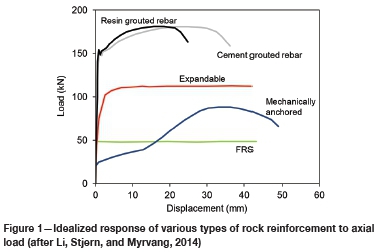
Resin-grouted rebar bolts are used widely in underground hard-rock mines. The main difference between these and cement-grouted rebar bolts is the use of a cartridge polyester resin product as a bonding agent. Ideally, the resin forms a continuous column along the bolt length and therefore this bolt type is classified as a continuously mechanically coupled bolt (Thompson, Villaescusa, and Windsor, 2012). Failure of the rockbolt system can occur either along the steel rebar through yielding and eventual rupture, or in the grout medium leading to a pull-out type failure. Compared to cement-grouted rock bolts, the use of a polyester resin for the grout medium typically results in a stiffer bolt response and a higher pull-out capacity. Therefore, the resin-grouted rebar bolt is considered as a stiff reinforcement unit, which resists limited yield before rupture. While both resin- and cement-grouted rebar bolts are considered as continuously mechanically coupled bolts, the failure of the fully grouted resin rebar bolt in hard rock conditions usually occurs with the rebar dowel, rather than a pull-out type failure of the grout. Representative behaviour of the resin-grouted rebar to pull test conditions along with other types of rock reinforcement - cement-grouted rebar, expandable, mechanically anchored, and friction rock stabilizers (FRS) - can be seen in Figure 1.
Much of the earlier literature on grouted rebar bolts focuses on the cement-grouted rebar, rather than the resin-grouted rebar. Examples include the trilinear model suggested by Benmokrane,
Chennouf, and Mitri (1995) with subsequent investigations by Ren et al. (2010), Liu, Huang, and Li (2012), and Ma, Nemcik, and Aziz (2016), which focus on the pull-out failure of the cement grouted rebar. Li, Kristjansson, and H0ien (2016) investigated the effects of water content of cement on the critical embedment length of rebar. He, An, and Zhao (2015) used the alternative grouted rebar model proposed by Li and Stillborg (1999) to analytically investigate the cement-grouted rebar under a variety of loading conditions, including pull-out tests.
Pull testing
In-situ pull test
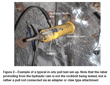
Pull testing is a part of the QC/QA programme of many Ontarian underground mines. Pull tests are also undertaken prior to the introduction of new reinforcement products to verify the validity of axial load capabilities stated by the suppliers and demonstrate that the selected rockbolts can be successfully installed in local conditions. When performed at regular intervals, pull tests can alert mine personnel to changes in rockbolt behaviour or demonstrate continued capacity under changing ground conditions. Figure 2 shows an example of a typical in-situ pull test set-up.
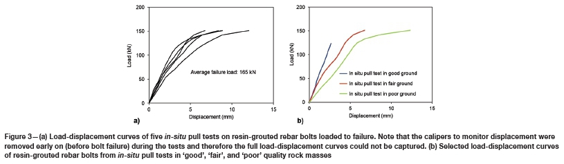
Variations are numerous, though a variation of note is that the pull tests for resin-grouted rebar are not typically performed to failure. Testing personnel report a safety concern due to the possibility of the broken rockbolt being ejected at high speed in an enclosed area. A less dramatic concern is the potential for damage to the testing equipment and instrumentation with relaxation and movement of the loading system. Thus, a complete load-displacement curve with accompanying information about the ground condition of a resin-grouted rebar tested to failure is rarely available. Figure 3a shows the load-displacement curves of five in-situ pull tests from two underground mines in which the load was applied until failure. In these tests, the caliper used to measure the displacement was removed well before the bolt rupture and, therefore, the full load-displacement curves were not obtained. The failure load recorded from these tests was between 151 kN and 171 kN, with an average failure load being 165 kN.
Figure 3b shows the load-displacement curves of selected in-situ pull tests on 20 mm diameter resin-grouted rebar bolts in 'good', 'fair', and 'poor' quality rock masses (according to the Q-values provided by the mines). These tests were not carried out to the failure of the bolt, with the test performed in good quality rock not reaching the yield load. As can be seen in Figure 3b, the bolts' load-displacement responses are highly linear during the initial loading stages. The rebar bolt in 'good' ground demonstrates a much stiffer behavior than those in 'fair' and 'poor' grounds. These tests were conducted with representatives of the ground support supply company present in addition to mine personnel.
Laboratory pull test
A better understanding of the behavior of rockbolts under pull load conditions can be obtained using controlled laboratory experiments. Laboratory testing of rebar bolts follows four broad classes: pull, shear, combined pull and shear, and push tests. Laboratory pull tests use a loading frame to pull the bolts installed into blocks or cylinders of cement or rock (Stimpson, 1984; Korzeniowski, Skrzypkowski, and Herezy, 2016). A common approach for combined load tests is to install a rebar orthogonally across two concrete blocks, which can be loaded with a combination of axial and shear loads (Stillborg, 1993; Stjern, 1995; Chen, 2014), though differing geometries have also been used (Grasselli, 2005). Push tests resemble laboratory pull tests, though the bolts are pushed and typically shorter lengths are used (Li, Kristjansson, and Hoien, 2016; Ma, Nemcik, and Aziz, 2014; Cao, Ren, and Cook, 2013).
Unfortunately, the number of well documented in-situ pull test results is limited. Most of the available information on the performance of different rockbolt types comes from laboratory tests under simulated discontinuity conditions whereby a load is applied to a bolt embedded in two concrete blocks, e.g. Stillborg (1993), Chen (2014). Further complicating the issue is that most laboratory tests dealt with the cement-grouted rebar bolt rather than the resin-grouted rebar bolt. Nevertheless, the Stjern's (1995) data-set offers load-displacement curves of a variety of rockbolts, including resin-grouted rebar bolts, which were axially loaded to failure.
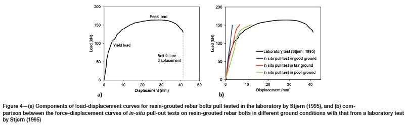
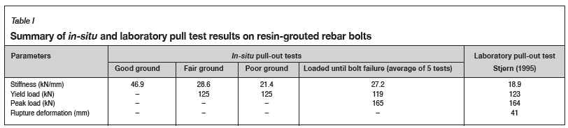
Figure 4a shows the full load-displacement curve from a laboratory pull test on a fully resin-grouted rebar bolt by Stjern (1995). As can be seen, under pull loading condition, the resin-grouted rebar bolt elongates elastically, then yields and hardens until it reaches the peak load. The bolt continues to elongate until rupture occurs. Figure 4b compares the load-displacement curves from a laboratory pull test on resin-grouted rebar bolt by Stjern (1995) and those of the in-situ pull test presented earlier. It is evident that the initial stiffness in the laboratory test corresponds with that of the in-situ pull test conducted in 'fair' ground, whereas the yield behaviour of the rebar bolt in the laboratory follows that of the in-situ pull-out test in 'poor' ground. It should be noted that the peak load obtained from the laboratory test (164 kN) is close to the average peak load obtained from in-situ tests (165 kN) presented in Figure 3a. Table I compares the results of the laboratory pull test from Stjern (1995), in-situ tests for different ground conditions (Figure 3b), and in-situ tests conducted until bolt failure (Figure 3a), in terms of the initial stiffness, yield load, peak load, and bolt rupture displacement.
In this article, the results of the laboratory pull test on fully resin-grouted rebar bolt reported by Stjern (1995) and presented in Figure 4, in terms of the peak load and rupture displacement values (Table I), were first used to extrapolate the full load-displacement curves of the in-situ pull tests for different ground conditions presented in Figure 3b and Figure 4b. The extrapolated load-displacement curves were then used to simulate in-situ pull tests using an explicit reinforcement element and extrapolate the load-displacement response of fully resin grouted rebar bolts in different ground conditions.
Numerical simulation of in-situ pull tests
Numerical modeling plays an important role in the stability analysis and design of underground excavations. Continuum, discontinuum, and hybrid continuum-discontinuum codes have been used to simulate surface and underground excavations and various types of rock reinforcement and surface support. The choice of a particular numerical code is based on the type of the problem and the capacity of the code to represent the boundary conditions, adequately capture the material behaviour, and the pertinent failure mechanisms (Bahrani and Hadjigeorgiou, 2017). Other factors such as user's familiarity with particular software, data availability and variability, perceived need for complexity, and computational constraints are also important.
In recent years, various types of rock reinforcement models have been developed and implemented into the numerical codes. Bahrani and Hadjigeorgiou (2017) investigated the applicability of both implicit and explicit rock reinforcement models for simulating laboratory pull and shear tests on cement-grouted rebar bolts. They concluded that although both types of model can be used to represent rock reinforcement, for most practical purposes the explicit rockbolt model provides a more realistic simulation of the failure of both the bolt and the grout under diverse loading conditions.
The focus of this work is on investigating a single loading mechanism (axial load) of a resin rockbolt installed in three different ground conditions. In particular, it illustrates the challenges in the extrapolation of explicit reinforcement models from laboratory to in-situ conditions. This was achieved by simulating the in-situ pull tests on fully resin-grouted rebar bolts in the three different ground conditions presented in the previous section (Figure 3b).
Choice of modelling software and reinforcement element
The numerical simulation of rock reinforcement can be accomplished with material models (e.g. Ferrero, 1995; Grasselli, 2005; Aziz and Jalalifar, 2007) or by structural elements formulated in the software (e.g. Malmgren and Nordlund, 2008; Liu, Huang, and Li, 2012; Gao, Stead, and Kang, 2015; Karampinos, Hadjigeorgiou, and Turcotte, 2016; Karampinos, Hadjigeorgiou, and Pierce, 2018; Bahrani and Hadjigeorgiou, 2018). Both approaches are valid, although the fine mesh size requirements for simulating rock reinforcement via material models are computationally intensive. Consequently, structural elements are the preferred approach for the simulation of large-scale mining problems.
The two-dimensional Universal Distinct Element Code, UDEC, developed by Itasca Consulting Group (Itasca, 2014), was used in this study to simulate the in-situ pull test on a fully resin-grouted rebar bolt. UDEC offers three structural elements for simulating rock reinforcement; the 'local' reinforcement element, the 'global' shearing-resistant reinforcement element, and the 'global' bending- and shearing-resistant reinforcement element (Itasca, 2014). The 'local' and 'global' reinforcement elements are examples of implicit and explicit reinforcement models.
The 'local' reinforcement element does not act over intact rock, but only over the discontinuities in the modelled jointed rock mass. In this study, given the lack of information on discontinuities, the pull tests are simulated in an equivalent continuum rock mass, and this precludes the use of the 'local' reinforcement element. The 'global' reinforcement element in UDEC comes in two types: 'cable' and 'rockbolt' elements. The 'cable' element is a shearing-resistant element, which provides very little resistance to bending, while the 'rockbolt' element provides sufficient resistance to both shearing and bending. Both types of 'global' reinforcement elements require input parameters for the dowel (e.g. geometry, modulus of elasticity, yield load) as well as parameters for the grout and grout-rock interface (e.g. grout strength and stiffness). While both the 'cable' and 'rockbolt' elements can be used to simulate continuously mechanically coupled bolts, the 'rockbolt' element is well-suited to represent rock reinforcement in which the nonlinear effects of confinement, grout or resin bonding, or tensile rupture are important.
Bahrani and Hadjigeorgiou (2017) demonstrated that when the 'cable' element is used to simulate a rebar bolt, its capacity in the laboratory shear test is underestimated. This has implications for ground support design and stability analysis of underground excavations in jointed rock masses. The use of the 'cable' element instead of the 'rockbolt' element may result in an underestimation of the rebar bolt's bending capacity, which may lead to a conservative design of the support system.
Another advantage of the 'rockbolt' element over the 'cable' element, demonstrated by Bahrani and Hadjigeorgiou (2017), is its explicit representation of bolt failure. The 'rockbolt' element can capture the actual bolt breakage based upon a user-defined tensile failure strain limit. Therefore, the 'rockbolt' element was chosen in this study to simulate the in-situ pull test.
Global reinforcement ('rockbolt' element)
As shown in Figure 5, the 'rockbolt' element is divided into a number of segments of length L, with nodal points located at each segment end. The 'rockbolt' element interacts with the surrounding rock medium via shear and normal coupling springs, which are connectors that transfer forces and motion between the 'rockbolt' element and the grid-points associated with the block zone, in which the nodes are located (Figure 5).
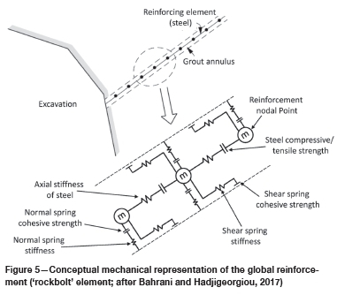
The 'rockbolt' element segments are treated as a linearly elastic material that may yield in the axial direction either in tension or compression. The tensile and compressive yield strengths are used to define the strength limits. Inelastic bending is simulated in this element by specifying a limiting plastic moment. This means that the 'rockbolt' elements behave elastically until they reach the plastic moment. In addition, segments may break and separate at the nodes, based on a user-defined tensile failure strain limit. A strain measure, called the 'total plastic tensile strain', based on adding the axial and bending plastic strains, is evaluated at each node. If this strain exceeds the tensile failure strain limit, the forces and moment in this segment are set to zero and the 'rockbolt' element is assumed to have failed (Itasca, 2014).
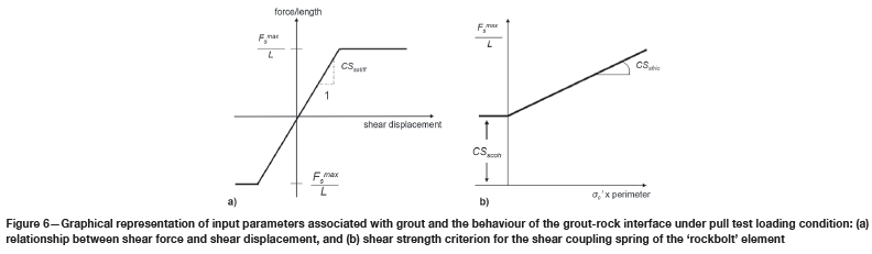
Figure 6 shows the grout parameters in reference to displacement and load for the 'rockbolt' element. Under an idealized pull test, as simulated numerically in this study, the loads are axial and therefore parameters regarding resistance to bending are not discussed.
The shear behavior of the interface during relative displacement between the element nodes and the grid-points is described numerically by the coupling spring shear stiffness (CSsstiff in Figure 6a) according to the following equation:

where Fsis the shear force that develops in the shear coupling spring, upand umare the axial displacement of the 'rockbolt' element and the medium (soil or rock), and L is the segment length. The limiting shear force (Fsmax) that can be developed along the 'rockbolt' element/grid-point interface is a function of the cohesive strength of the interface (CSscoh) and the stress-dependent frictional resistance (CSsßic) along the interface (Figure 6b) according to:

where the perimeter is the exposed perimeter of the rockbolt ( i.e., the length of the rockbolt surface that is in contact with the medium), and a'cis the mean effective confining stress normal to the 'rockbolt' element. Other parameters required for the simulation of rock reinforcement include the cross-sectional area, second moment of area, density, and elastic modulus of the bolt. Further details of the theoretical aspects of the 'rockbolt' element can be found in the UDEC manual (Itasca, 2014).
Model geometry and specification
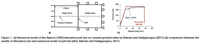
The 'rockbolt' element has been successfully employed in the past by Ma, Nemcik, and Aziz (2014), Nemcik etal. (2014), and Bahrani and Hadjigeorgiou (2017) to investigate various aspects of rock reinforcement. Ma, Nemcik, and Aziz (2014) used the 'rockbolt' element to simulate resin-grouted rebar bolts in underground coal mine roadways. Nemcik et al. (2014) also used this reinforcement element to simulate progressive shear force distribution and debonding of a fully grouted rockbolt subjected to tensile loading. Bahrani and Hadjigeorgiou (2017) used the 'rockbolt' element to simulate laboratory pull and shear tests on cement-grouted rebar bolts reported by Stjern (1995).
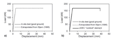
Figure 7 shows the geometry and boundary conditions of the UDEC model used by Bahrani and Hadjigeorgiou (2017), along with a comparison between the force-displacement curve from the laboratory pull test reported by Stjern (1995) and that from the calibrated model. As shown in Figure 7a, the UDEC model consisted of two elastic blocks separated by a frictional joint. The pull test was simulated by applying a velocity boundary to the left side of the left block while the sum of reaction forces developed on the boundaries of the right block was being monitored. The correspondence between the results of laboratory test and numerical simulations presented in Figure 7b suggests that the 'rockbolt' element is a suitable reinforcement model for the simulation of the behaviour of grouted rebar bolts under pull loading conditions.
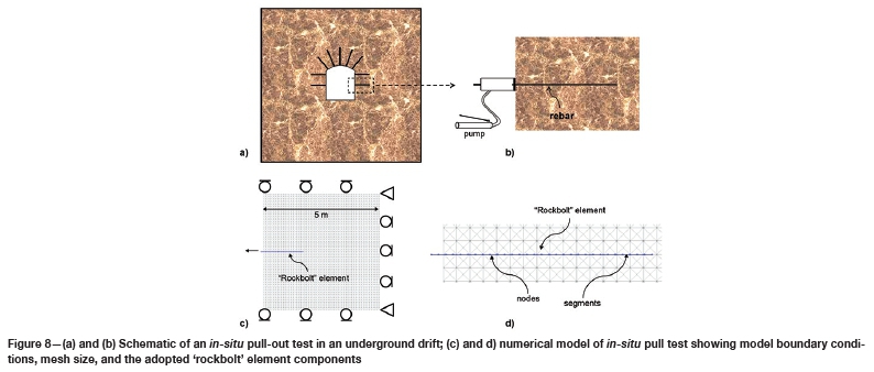
In practice, in-situ pull tests are usually conducted on the sidewalls of mining drifts. Figure 8a and Figure 8b show a schematic of an in-situ pull test in a drift. The geometry and the boundary conditions of the UDEC model, including the 'rockbolt' element, are presented in Figure 8c and Figure 8d, respectively. The geometry of the host rock is a 5 m χ 5 m elastic block with a 'rockbolt' element protruding 10 cm from the centre of the left boundary. As shown in Figure 8c, the pins and rollers were used for the model corners and sidewalls, respectively, to approximate the in-situ condition. The size and shape of the zones (mesh elements) were chosen to align the embedded rockbolt to the mesh elements (Figure 8d).
The pulling action was applied to the last node on the left side of the 'rockbolt' element with a fixed velocity in the negative x-direction, as shown with the arrow in Figure 8c. Forces acting on the rockbolt were recorded directly by summing the internal forces in the x-direction. The summation of reaction forces on the right model boundary was also recorded. A comparison of the two methods acted as a check for errors with the model construction and calculations.
Model calibration and results
For the purpose of this investigation, the model was assigned equivalent continuum rock mass elastic properties, obtained from the selected pull test reports. During the calibration process, it was noted that the elastic properties of the rock mass have no influence on the load-displacement response of the 'rockbolt' element. Therefore, the rock mass in all the models was assigned an elastic modulus of 40 GPa and a Poisson's ratio of 0.21.
The UDEC model was initially calibrated to the in-situ pull test force-displacement curves presented in Figure 4b. As discussed earlier, only the elastic portion of the load-displacemen curve of the rebar bolt in the case of the 'good' ground, and the elastic and the initial yielding sections of the load-displacement curve of the rebar bolt in the cases of the 'fair' and 'poor' grounds, were available from the in-situ pull test results. Therefore, the model calibration was initially carried out with respect to the elastic stiffness of the force-displacement curve of the in-situ pull tests by adjusting the shear coupling spring stiffness of the 'rockbolt' element. Note that the stiffness of the load-displacement curve from an in-situ pull test is a function of the bolt-grout contact stiffness, grout stiffness, and the grout-rock mass contact stiffness. Therefore, the value of the shear coupling spring stiffness obtained from the calibration process accounts for all three components.
The calibration was continued by matching the peak load corresponding to the average failure load of the in-situ pull tests loaded to failure (presented in Figure 3a) and the rupture displacement obtained from the results of laboratory pull test on resin-grouted rebar bolt reported by Stjern (1995) (shown in Figure 4a and summarized in Table I).
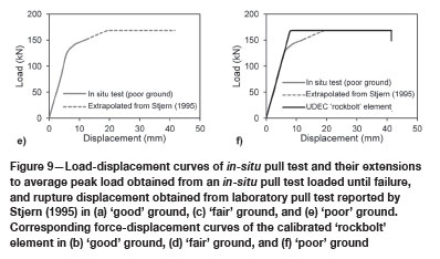
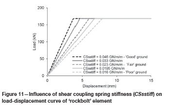
Figure 9a, Figure 9c, and Figure 9e show the load-displacement curves from the in-situ pull tests for the three ground conditions (solid lines) and their linear extrapolation (dashed lines) to the peak load followed by plastic deformation until bolt rupture at a displacement corresponding to that from the result of laboratory test reported by Stjern (1995). Figure 9b, Figure 9d, and Figure 9f show the force-displacement curves of the calibrated model in comparison with those presented in Figure 9a, Figure 9c, and Figure 9e. In all three cases, the 'rockbolt' elements failed at the element node just outside the simulated rock mass, indicating the failure of the steel (Figure 10).
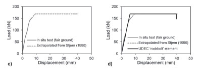
As illustrated in Figures 3 and 4, the load-displacement curves of selected in-situ pull tests on 20 mm diameter resin grouted rebar bolts in 'good', 'fair', and 'poor' quality rock show a relatively linear behaviour during the initial loading stages. For the purposes of the numerical models, these were further approximated to an idealized linear behaviour (Figure 9). It is acknowledged that a linear extrapolation of the in-situ pull tests is in effect an approximation. Nevertheless, in light of the relative approximations in all input parameters of the constructed numerical model, this is a reasonable trade-off.
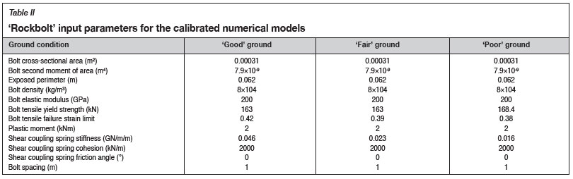
The values of the 'rockbolt' element input parameters obtained from the calibration process are listed in Table II. As can be seen from this table, the main difference between the calibration results for the three ground conditions is the value of the shear coupling spring stiffness. In the case of 'good' ground, a higher shear coupling spring stiffness value was required to capture the higher initial stiffness of the load-displacement curve compared to those of the 'fair' and 'poor' grounds.
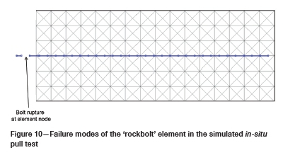
Further numerical simulations were conducted to investigate the influence of shear coupling spring stiffness (CSsstiff on the force-displacement behavior of the 'rockbolt' element. For this purpose, two more models were run with different CSsstiff -values, as demonstrated in Figure 11.
As can be seen in Figure 11, the slope of the linear section of the force-displacement curve decreases with decreasing value of the shear coupling spring stiffness, the parameter that accounts for the bolt-grout contact stiffness, the grout stiffness, and the grout-rock mass contact stiffness. Assuming that the bolt and grout conditions are constant, it can be concluded that the rock mass quality plays the main role in the behaviour of the force-displacement response of a rebar bolt during in-situ pull tests. It is suggested that the results of numerical modeling of in-situ pull tests using the 'rockbolt' element in terms of their input parameters (presented in Table II and Figure 11) can be used in large-scale continuum elastic models for the simulation of resin-grouted rebar bolts in varying ground conditions.
Conclusions
Although investigations on the influence of ground support on the stability of excavations are increasingly common, they are not matched by efforts to understand the implication of how reinforcement elements are implemented in the numerical models. Another concern is that even when sensitivity studies are employed to identify the implication of recommendations of variation in input data, these are often limited to information on the rock mass condition. The impact of ground support properties, of the same rockbolt type, is often overlooked.
This is illustrated in this paper by focusing on a relatively simple loading mechanism: pull-out testing of a rock reinforcement element. This paper employed numerical models to investigate the behaviour of resin-grouted rebar bolts in a range of ground conditions. It addresses some of the challenges associated with the explicit representation of rock reinforcement elements in stress analysis models. The main focus of the paper is on accounting for the influence of using field and laboratory data as input parameters for the models. For these purposes, we employed in-situ pull test data from underground hardrock mines in Ontario, Canada, as opposed to generic values provided by suppliers. The numerical models captured the load-displacement response and the failure mode of these bolts under axial loading conditions. This work highlights the impact of field data in the simulation of resin-grouted rebar bolts in mine-wide continuum models and has significant implications in the interpretation of the results from numerical modelling.
Acknowledgements
This study was funded by the Ontario Ministry of Labour Research Opportunities Program. The authors acknowledge the participation of the ground control committee of Workplace Safety North Ontario in collecting the field data.
ORCiD ID:
P. Tomasone: https://orchid.org/0000-00030900-4430
N. Bahrani: https://orchid.org/0000-0001-6479-9577
J. Hadjigeorgiou: https://orchid.org/0000-0002-6047-3964
References
Aziz, N. and Jalalfar, H. 2007. Experimental and numerical study of double shearing of bolt under confinement. Proceedings of the 26th International Conference on Ground Control in Mining. Peng, S.S., Mark, C., Finfinger, G., Tadolini, S., Khair, A.W., Heasley, K., and Luo, Y. (eds). Morgantown, WV. West Virginia University. pp. 242-249. [ Links ]
Bahrani, N. and Hadjigeorgiou, J. 2018. Influence of stope excavation on drift convergence and support behavior: Insights from 3D continuum and discontinuum models. Rock Mechanics and Rock Engineering, vol. 51. pp. 2395-2413. [ Links ]
Bahrani, N. and Hadjigeorgiou, J. 2017. Explicit reinforcement models for fully-grouted rebar rock bolts. Journal of Rock Mechanics and Geotechnical Engineering, vol. 9. pp. 267-280. [ Links ]
Benmokrane, B., Chennouf, A., and Mirra, H.S. 1995. Laboratory evaluation of cement-based grouts and grouted rock anchors. International Journal of Rock Mechanics and Mining Sciences & Geomechanics Abstracts, vol. 32. pp. 633-642. [ Links ]
Bobet, A. and Einstein, H.H. 2010. Tunnel reinforcement with rockbolts. Tunnelling and Underground Space Technology, vol. 26 pp. 100-123. [ Links ]
Cao, C., Ren, T., and Cook, C. 2013. Calculation of the effect of Poisson's ratio in laboratory push and pull testing of resin-encapsulated bolts. International Journal of Rock Mechanics & Mining Sciences, vol. 64. pp. 175-180. [ Links ]
Chen, Y. 2014. Experimental study and stress analysis of rock bolt anchorage. Journal of Rock Mechanics and Geotechnical Engineering, vol. 6. pp. 428-437. [ Links ]
Ferrero, A.M. 1995. The shear strength of reinforced rock joints. International Journal of Rock Mechanics and Mining Science & Geomechanics Abstracts, vol. 32. pp. 595-605. [ Links ]
Gao, F., Stead, D., and Kang, H. Numerical simulation of squeezing failure in a coal mine roadway due to mining-induced stresses. Rock Mechanics and Rock Engineering, vol. 48. pp. 1635-1645. [ Links ]
Grasselli, G. 2005. 3D behaviour of bolted rock joints: Experimental and numerical study. International Journal of Rock Mechanics and Mining Sciences, vol. 42. pp. 13-24. [ Links ]
Gustafson, A., Schunnasson, H., Timusk, M., and Hauta R. 2016. Productivity of rock reinforcement: methodology development. Journal of the Southern African Institute ofMining and Metallurgy, vol. 116. pp. 1127-1134. [ Links ]
Hadjigeorgiou, J. 2012. Where do the data come from? Transactions of the Institution ofMining and Metallurgy: Section A: Mining Technology, vol. 121, no. 4. pp. 36-247. [ Links ]
Hadjigeorgiou, J. and Tomasone, P. 2018. Characterising the behaviour of rock bolts based on in-situ pull tests. Caving 2018 - Proceedings of the Fourth International Symposium on Block and Sublevel Caving, Vancouver, Canada, 15-17 October 2018. [ Links ]
Potvin, Y. and Jakubec, J. (eds.). Australian Centre for Geomechanics. pp. 727-734. [ Links ]
Hadjigeorgiou, J. and Charette, F. 2001. Rock bolting for underground excavations. Underground Mining Methods - Engineering Fundamentals and International Case Studies. Society of Mining, Metallurgy, and Exploration (SME), Littleton, CO. pp. 547-554. [ Links ]
He, L., An, X.M., and Zhao, Z.Y. 2015. Fully grouted rock bolts: An analytical investigation. Rock Mechanics and Rock Engineering, vol. 48. pp. 1181-1196. [ Links ]
Itasca 2014. UDEC - Universal Distinct Element Code, Ver. 6.0. Itasca Consulting Group, Inc., Minneapolis, MN. [ Links ]
Joughin W.C. 2017. Dealing with uncertainty and risk in the design of deep and high stress mining excavations. Deep Mining 2017: Proceedings of the Eighth International Conference on Deep and High Stress Mining. Wesseloo, J. (ed.). Australian Centre for Geomechanics, Perth. pp. 489-507. [ Links ]
Karampinos, E., Hadjigeorgiou, J., and Pierce, M. 2018. Explicit representation of rock reinforcement in 3D DEM models of foliated ground. Journal of the Southern African Institute of Mining and Metallurgy, vol. 118. pp. 1243-1250. [ Links ]
Karampinos, E., Hadjigeorgiou, J., and Turcotte, P. 2016. Discrete element modelling of the influence of reinforcement in structurally controlled squeezing mechanisms in a hard rock mine. Rock Mechanics and Rock Engineering, vol. 49. pp. 4869-4892. [ Links ]
Korzeniowski, W.H., Skrzypkowski, K., and Herezy, L. 2016. Strain of steel rebar vs. rock bolt elongation on a laboratory stand. Proceedings of Ground Support 2016. Luleá, Sweden, 12-14 September. 2016. [ Links ]
Nordlund, E., Jones, T., and Eitzenberger, A. (eds). Luleá University of Technology. [ Links ]
Li, C. and Stillborg, B. 1999. Analytical models for rock bolts. International Journal of Rock Mechanics and Mining Sciences, vol. 36. pp. 1013-1029. [ Links ]
Li, C., Kristjansson, G., and Hoien, A.H. 2016. Critical embedment length and bond strength of fully encapsulated rebar rockbolts. Tunnelling and Underground Space Technology, vol. 59. pp. 16-23. [ Links ]
Li, C., Stjern, G., and Myrvang, A. 2014. A review on the performance of conventional and energy-absorbing rockbolts. Journal of Rock Mechanics and Geotechnical Engineering, vol. 6. pp. 315-327. [ Links ]
Liu, B., Huang, D., and Li, D.Y. 2012. Analytical formulation on the mechanical behavior of anchorage interface for full-length bonded bolt. Applied Mechanics and Materials, vol. 166-169. pp. 3254-3257. [ Links ]
Lorig, L. and Varona, P. 2013, Guidelines for numerical modelling of rock support for mines. Proceedings of the Seventh International Symposium on Ground Support in Mining and Underground Construction. Brady, B. and Potvin, Y. (eds). Australian Centre for Geomechanics, Perth. pp. 81-106. [ Links ]
Ma, S., Nemcik, J., and Aziz, N. 2014. Simulation of fully grouted rockbolts in underground roadways using FLAC2D. Canadian Geotechnical Journal, vol. 51. pp. 911-920. [ Links ]
Ma, S., zhao, Z., Nie, W., and Gui, Y. 2016. A numerical model of fully grouted bolts considering the tri-linear shear bond-slip model. Tunnelling and Underground Space Technology, vol. 54. pp. 73-80. [ Links ]
Malmgren, L. and Nordlund, E. 2008. Interaction of shotcrete with rock and rock bolts - A numerical study. International Journal of Rock Mechanics and Mining Sciences, vol. 45. pp. 538-553. [ Links ]
Nemcik, J., Ma, S., Aziz, N., Ren, T., and Geng, X. 2014. Numerical modelling of failure propagation in fully grouted rock bolts subjected to tensile load. International Journal of Rock Mechanics and Mining Sciences, vol. 71. pp. 293-300. [ Links ]
Ren, F.F., Yang, Z.J., Chen, J.F., and Chen, W.W. 2010. An analytical analysis of the full-range behaviour of grouted rockbolts based on a tri-linear bond-slip model. Construction and Building Materials, vol. 24. pp. 361-370. [ Links ]
Stillborg, B. 1993. Rockbolt tensile loading across a joint. Proceedings of the International Mine Water Association Symposium, Chililabombwe, Zambia. IMWA, Wendelstein, Germany. pp. 587-604. https://www.imwa.info/docs/imwa_1993/IMWA_1993_Stillborg_587-604.pdf [ Links ]
Stimpson, B. 1984. A simple rock bolt pull-out test device for teaching purposes. International Journal of Rock Mechanics and Mining Science & Geomechanics Abstracts. vol. 24. pp. 217-218 [ Links ]
Stjern, G. 1995. Practical performance of rock bolts. PhD thesis, Norwegian University of Science and Technology. [ Links ]
Thompson, A.G., Villaescusa, E., and Windsor, CR. 2012. Ground support terminology and classification: An update. Geotechnical and Geological Engineering, vol. 30. pp. 553-580. [ Links ]
Wiles, T.D. 2006. Reliability of numerical modelling predictions. International Journal of Rock Mechanics and Mining Sciences, vol. 43. pp. 454-472. [ Links ]
 Correspondence:
J. Hadjigeorgiou
Email: john.hadjigeorgiou@utoronto.ca
Received: 14 Nov. 2019
Revised: 17 Apr. 2020
Accepted: 21 May 2020
Published: June 2020

