


Serviços Personalizados
Artigo
 Inglês (pdf)
 Artigo em XML
 Referências do artigo
Indicadores

Links relacionados
-
 Citado por Google
 -
 Similares em Google
Compartilhar

 Permalink
Journal of the Southern African Institute of Mining and Metallurgy
versão On-line ISSN 2411-9717
versão impressa ISSN 2225-6253
J. S. Afr. Inst. Min. Metall. vol.120 no.6 Johannesburg Jun. 2020
http://dx.doi.org/10.17159/2411-9717/1053/2020
STUDENT PAPERS
Characterization of surface roughness and subsurface pores and their effect on corrosion in 3D-printed AlSilOMg
S. ThuketanaI, *; C. TauteI; H. MöllerI; A. du PlessisII, III
IDepartment of Materials Science and Metallurgical Engineering, University of Pretoria, Pretoria, South Africa
IIResearch Group 3DInnovation, Stellenbosch University, Stellenbosch, South Africa
IIIDepartment of Mechanical Engineering, Nelson Mandela University, Port Elizabeth, South Africa
SYNOPSIS
Denel Dynamics, a South African armaments development and manufacturing company, is interested in introducing additive manufacturing (AM) in the fabrication of missile components. The practicality of using AM for industrial applications, considering its unique challenges, was questioned. To investigate this, defects (surface roughness and porosity) associated with AlSi10Mg parts produced by laser powder bed fusion were characterized. In this case study, 40 rectangular, 30 mm χ 20 mm χ 4 mm samples, 20 of which were 'smooth' (3.7 μm Ra) and 20 'rough' (7.3 μm Ra), were analysed. The surface roughness, porosity volume percentage, and the porosity type were characterized using stereo, optical, and scanning electron microscopy as well as nano-CT scans. The pores were observed to be located in the subsurface of the samples. The smooth and rough samples were found to have subsurface pores mainly positioned between 100-650 μm and 220-600 μm from the surface, respectively. To improve the surface roughness, the samples were polished by centrifugal barrel finishing (CBF). Smooth (polished) and unpolished samples were corroded using potentiodynamic tests in a 3.5% NaCl solution. The smooth, polished samples were found to undergo more corrosion than the unpolished samples. This unexpected result could be explained by the subsurface pores of the polished samples being exposed after surface layers were removed during CBF. The location of porosity in 3D printed samples is therefore of high importance when surface polishing is done before exposure to a corrosive environment. Even though CBF decreases the surface roughness, subsurface pores that are exposed during polishing are detrimental to pitting corrosion resistance. Laser shock peening, which has been found to successfully close pores as deep as 700 μm without compromising the surface roughness, is suggested as a possible solution.
Keywords: additive manufacturing, laser powder bed fusion, surface roughness, porosity, corrosion.
Introduction
Additive manufacturing (AM) has the ability to produce complex structures directly from a design without the need for expensive tooling. The need to assemble multiple components is reduced and intricate parts can be produced in one step (Debroy, 2018). The standard terminology for AM, ISO/ ASTM 52900:2015 (E), defines powder bed fusion (PBF) as a 'manufacturing process in which thermal energy selectively fuses regions of a powder bed'. PBF uses either a focused laser beam or an electron beam; this study will focus on laser powder bed fusion (L-PBF). L-PBF entails some challenges introduced by the repeated melting, rapid solidification thermal cycles, directional heat extraction, and repeated solid-state transformations during the printing process (Cabrini et al., 2018). The challenges include, but are not limited to, the difficulty in producing dense parts, residual stresses which result in distortion and cracking, and high surface roughness and the subsequent requirement for postprocessing (Aboulkhair et al., 2014). The powders used to fabricate the parts play an important role in determining their quality. The powders may be characterized in terms of morphology, density, and flowability. Spherical powders are used to produce dense parts in complex designs, particularly when the material of construction includes precious metals such as platinum (Pt), rhodium (Rh), iridium (Ir), and their alloys (Bisset and van der Walt, 2017).
AlSi10Mg powder is the most commonly used material to produce aluminium alloy parts via L-PBF. AlSi10Mg is a near-eutectic alloy in which the eutectic Si counters solidification shrinkage, hence reducing the printed part's susceptibility to cracking. The size distribution and particle shape of the powder play a critical role in determining the quality of the built part. Spherical particles give good flowability, resulting in uniform layers on the built part. The particle size distribution also affects the interaction between the laser and powder bed. Fine particles have an adverse influence on flowability, and large particles require higher laser energy to cause melting. Powder particles with internal porosity can introduce porosity to the built part (Lumley, 2018).
Surface roughness in laser powder bed fusion
Depending on the process parameters and powder size used, the typical surface roughness of aluminium components produced by L-PBF ranges between 8 μm and 20 μm Ra (Cabrini et al., 2016). Before polishing, the texture exhibits an excessive number of cavities and other surface imperfections such as limited bonding of particles to the substrate material (Leon and Aghion, 2017). According to Nasab et al. (2018) there are three main surface defects that cause L-PBF parts to have high surface roughness - balling, spatter particles, and partially melted powder. Balling is a result of a division effect of an elongated melt pool. Spatter particles are usually about 200 μm in size. When particles spatter from the melt pool and land within the powder bed surface, they are remelted together with the following layer. If, however, the spatters are close to the contour, they will only be partially melted and remain attached to the surface. The partially melted powder is the same size as the powder particles, which is typically between 20 μm and 50 μmm.
Porosity in laser powder bed fusion
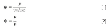
The scanning speed and energy density play opposing roles in the type of pores formed within a part. Energy density can refer to volumetric energy density (ψ), defined by the combined effect of laser power (P), scanning speed (v), hatch spacing (h), and powder layer thickness (t), as seen in Equation [1] (Lumley, 2018). It can also refer to linear energy density (Φ), defined by the combined effect of laser power and scanning speed, as seen in Equation [2] (Wang, 2011).
At high scanning speeds, metallurgical pores (commonly known as 'lack of fusion' pores) have been observed. These pores are irregular in shape and are present due to incomplete melting. At low scanning speeds, keyhole pores have been observed. These are spherical in shape and are a result of trapped metal vapour in a deeply penetrating melt pool (Lumley, 2018). The number of pores can be minimized at intermediate energy densities and scanning speeds, but never completely eliminated (Tang, Pistorius, and Beuth, 2017). In a study by du Plessis (2019), a range of process parameter changes and their effect on subsurface pore distributions in L-PBF parts was demonstrated. Optimal parameters achieved up to 99.99% density (0.01% porosity). The different pore formation mechanisms and their resulting morphologies and 3D distributions were reported. The optimal energy densities differ from material to material and machine to machine.
Laser powder bed fusion parameters
There are many variables considered in L-PBF. Aboulkhair et al. (2014) categorize them as laser-, scan-, powder-, and temperature-related. When one of these variables is changed, the quality of the built part may be affected. The effect may be seen in the microstructure, crystallographic texture, surface roughness, and/or the density. An increase in hatch spacing has been found to cause pores to become more irregular in shape, thus decreasing the density of L-PBF parts. Balling increases with greater scanning speed, resulting in a lower surface quality part (Aboulkhair et al., 2014). Shielding gas flow has also been observed to affect the built part's quality (Philo, 2017). Shielding gas flow in L-PBF is used mainly to provide an inert atmosphere to reduce reactive gas pickup at the liquid metal, chiefly to avoid oxidation and nitration. This is particularly common during the production of aluminium alloys. Inhomogeneous gas flow over a build platform results in insufficient removal of by-products such as spatter, hence increasing the surface roughness.
Corrosion of aluminium alloys
Effect of surface roughness on corrosion
The rough surface from L-PBF causes some changes in corrosion behaviour. Cabrini et al. (2016) stated that the passive film formed on aluminium alloys during L-PBF is less protective than the oxide spontaneously formed in air. Leon and Aghion (2017) investigated the effect of AM surface roughness defects on corrosion after exposure of AlSi10Mg samples to 3.5% NaCl for 30 days. The study found that the polished samples showed better corrosion resistance than the unpolished samples. Corrosion attack at the unpolished surface was manifest by multiple sites of pitting and an increase in corrosion products. The polished samples displayed shallow pits, whereas the unpolished samples showed deeper and more irregularly shaped pits. The study linked the reduced corrosion resistance of unpolished samples to increased surface roughness in the form of large cavities and other surface defects that were caused by the L-PBF process.
Effect of porosity on corrosion
Pores act as preferential initiation sites for localized corrosion (Cabrini et al., 2016). Leon, Shirizly, and Aghion (2016) compared AlSi10Mg produced through L-PBF and a gravity-cast alloy. The corrosion fatigue endurance of the L-PBF alloy was found to be better than that of the gravity cast alloy. This was attributed mainly to the significant differences between the microstructure and porosity. It is believed that the accelerated cracking in the cast alloy was due to the synergistic effect of the corrosive environment and the stress concentration from the irregular pores in the gravity-cast alloy. Although the printed alloy had the best corrosion resistance of the two alloys, it was concluded that the AM porosity defect affected the corrosion resistance of the alloy adversely due to the corrosion attack progressing along the melt pool overlap, which lacked fusion pores caused by L-PBF. Due to the significant influence of porosity on corrosion resistance, the effect of the different microstructures was not ascertained conclusively.
Principle objective and scope of work
South Africa had a late start with AM, the first system becoming available in 1991. Now, however, a complete value chain has developed, with a well-balanced mix of basic and applied research (de Beer, 2011). As AM continues to grow and develop in South Africa, more industries have shown interest in the technology. Denel Dynamics, a South African armaments development and manufacturing company, is interested in introducing AM in the fabrication of missile components. The company produces stand-off weapons, air-to-air, ground-to-air, and armour-piercing missiles. These missiles, especially the air-to-air and stand-off weapons, can be exposed to a salt atmosphere. This makes good corrosion resistance an important factor in determining whether to adopt AM technology. This project aimed to characterize the defects associated with AlSilOMg parts produced through L-PBF that could possibly limit industrial applications. This was done by investigating the location of pores in the built parts, as this affects both corrosion resistance and fatigue life. The analysis was completed using nano-CT scans and optical, stereo, and scanning electron microscopy. Post-processes to improve surface roughness and porosity were also explored. This study was conducted as a final year undergraduate research project in the Department of Materials Science and Metallurgical Engineering at the University of Pretoria. Further research is planned and the topic will be expanded to include related in-depth aspects in future
Materials and methods
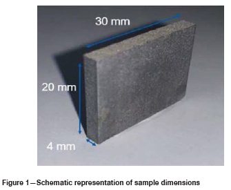
Tests were carried out on 40 L-PBF AlSi10Mg samples obtained using a SLM250 metal 3D printer (Wiiboox, China). The built-direction of the samples was in the X-Y plane. Half of the printed samples were received as 'rough' (7.3 μm Ra) and the other as 'smooth' (3.7 μm Ra) in surface. The smooth samples were placed closer to the gas outlet, which is believed to have caused the difference in the surface roughness. The laser, scan, powder, and temperature parameters were kept constant. All the samples were 30 mm χ 20 mm χ 4 mm in size, as shown in Figure 1.
All samples were weighed and dimensions and surface roughness measured upon arrival. Half the smooth and rough samples were polished by CBF using a HZ-40 machine (Mass Finishing Incorporated, USA). A representative number (>50%) of each sample type (as-received and polished) was measured. Each sample was measured at least three times for validity and repeatability. Surface roughness was measured using a mobile surface roughness machine (Zeiss Surfcom Flex Measuring System, ACRRETECH, Japan) that was calibrated and the stylus checked before the start of measuring. The surface quality was analysed using stereomicroscopy (Olympus SZX7 spectroscope, Japan). Porosity analysis was carried out by optical microscopy (Olympus BX51M, Japan) and nano-computer-aided tomography (CT) scans (du Plessis, le Roux, and Guelpa, 2016). The use of X-ray computed tomography in the field of additive manufacturing has been reviewed in detail by du Plessis et al. (2018). Surface roughness defects were then analysed using scanning electron microscopy (Jeol JSM-IT300LV, Japan).
Smooth, polished, and unpolished samples were corroded in a 3.5% NaCl solution by a potentiodynamic test using a potentiostat (PGSTAT302N, Metrohm, Switzerland). This was done to show the corrosion behaviour of the samples in an extreme corrosive environment. A three-electrode cell was used. The reference electrode was Ag/AgCl and platinum was the counter-electrode. Scanning was from -0.3 V to +0.3 V relative to the open circuit potential with a scanning rate of 0.125 mV/s. After the tests were completed, the sample surfaces were examined using optical microscopy (Olympus BX51M, Japan).
Results
Surface roughness
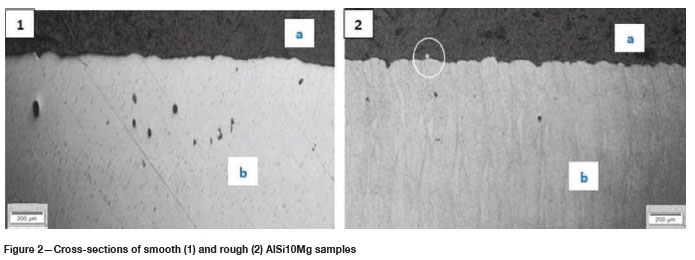
Figure 2 shows cross-sections of smooth and rough as-received samples from the Y-Z plane. The top black part (a) is Bakelite resin and the grey part (b) is the sample (all cross-sections in this report show the resin as black). In both the samples, 'valleys and peaks' were observed, with those in the rough sample being more prominent.
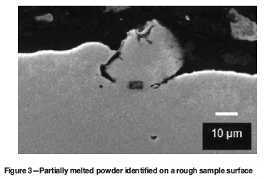
The surface roughness of the smooth samples measured from the X-Z plane ranged from 2.8 μπι to 4.0 μπι Ra with an average of 3.7 μm Ra. A surface defect, encircled in Figure 2 (2), and shown in a close-up view in Figure 3, was identified on the rough sample surface. The defect was identified as partially melted powder due to its size being between 20 and 50 μm (Nasab et al., 2018). These types of defect, together with the 'valleys' and 'peaks', caused a higher surface roughness in the rough samples. The rough sample surface roughness ranged from 5.5 μm to 9.5 μm Ra, with an average of 7.3 μm Ra, as measured from the X-Z plane.
Porosity
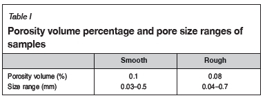
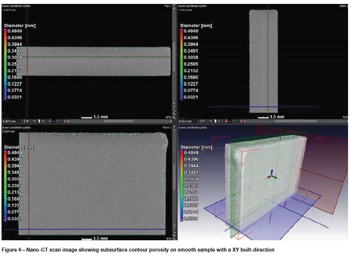
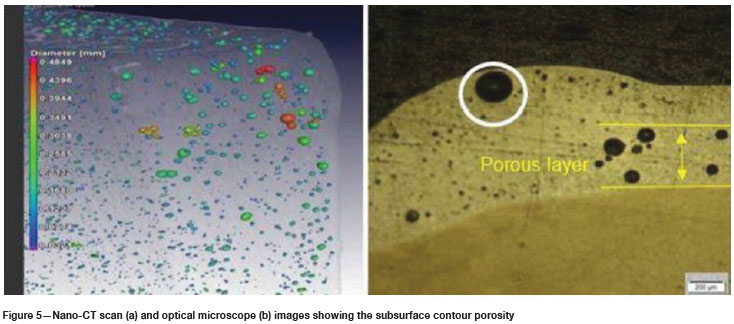
Nano-CT scans were used for the 3D quantification of porosity. Figure 4 is a nano-CT image of one of the 'smooth' samples that shows characteristics of both the smooth and rough samples. The size range of the pores and the porosity volume percentage for both types of sample are given in Table I. The porosity volume percentage of the smooth samples were observed to be slightly higher (by 0.02%) than for the rough samples. The pores for the X-Y plane built-direction samples were identified as subsurface, contour pores (du Plessis and le Roux, 2018). Figure 5 depicts both a nano-CT scan and an optical microscope image to show that the pores mainly line up to form a porous layer. Large pores can be found outside the layer at the corners of the samples. The encircled pore in Figure 5b presents a high risk for decreasing corrosion resistance as it is very close to the surface, and if exposed would act as an initiation site for localized corrosion.
Post-processing
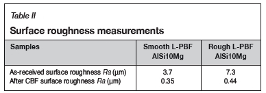
As discussed in the literature, surface roughness associated with L-PBF can be detrimental to corrosion resistance (Leon and Aghion, 2017). In an attempt to prevent the adverse effects of the surface quality, centrifugal barrel finishing (CBF) was done. Table II summarizes the surface roughness of the different L-PBF samples before and after CBF.
Images of the L-PBF AlSi10Mg samples before and after CBF are shown in Figure 6. From visual inspection, it is apparent that CBF improves the poor surface finish; however, upon further analysis it is seen that a new problem may be introduced. The porous layers of the smooth and rough samples, as well as the layers removed during CBF, were characterized using optical and dimensional analysis. Assuming uniform removal of material, the removed layer described in Table III represents half the material removed per plane.
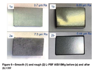
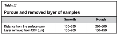
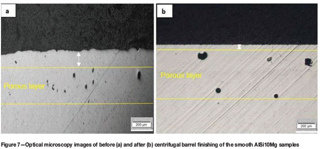
Table III reveals how the subsurface pores in the smooth samples were at risk of being exposed on the surface. To investigate this, cross-sections of the smooth samples were analysed using optical microscopy and nano-CT scans. Due to CBF, some surface material was removed, bringing the surface closer to the (initially) subsurface pores as shown in Figure 7.
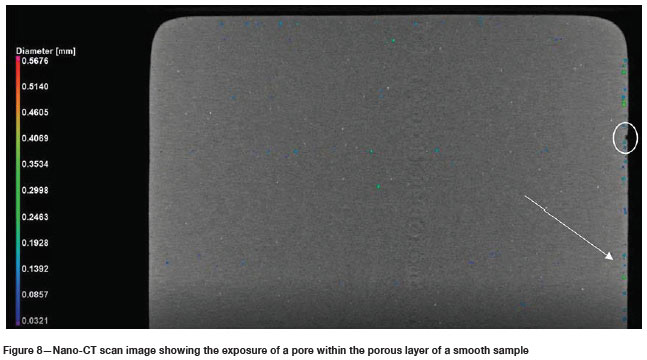
The nano-CT scans showed that the porous layer remains in the subsurface for some samples, and on the surface for others. Some scans, such as the one in Figure 8, revealed some subsurface pore exposure on the surface. The porous layer can be seen on the right-hand side of the sample, with an encircled exposed pore.
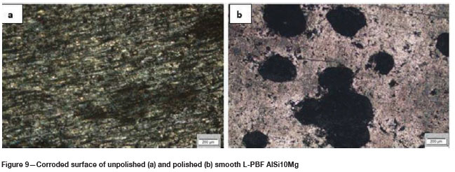
To investigate whether the porous layer after CBF affects the corrosion resistance, smooth polished and unpolished samples were corroded using potentiodynamic tests. The visual results from optical microscopy revealed that the polished samples experienced more corrosion, with more prominent pits than the unpolished samples. This can be seen in Figure 9.
Discussion and recommendations
One of the challenges of L-PBF is the difficulty in producing repeatable part quality. This was observed from the difference in surface roughness between the samples. The difference may be due to more spatters being removed by the gas from the smooth samples than from the rough samples (Philo, 2017). This was because the smooth samples were placed closer to the gas outlet, improving the homogeneity of the gas flow.
Previous studies found that surface roughness and porosity influence corrosion resistance negatively; however, these studies analysed the effects of these defects separately (Leon and Aghion, 2017; Leon, Shirizly, and Aghion, 2016). In this investigation we looked at how both these defects together affect corrosion resistance. Based on previous studies, the unpolished samples were expected to experience the most corrosion; however, those studies did not specify where the porosity in the parts was situated. From the present study, in the case of subsurface contour pores it was seen that not just surface pores, but also subsurface pores, may be detrimental to corrosion resistance.
Although the surface roughness of the analysed samples was smoother than is typical for L-PBF surfaces (Cabrini et al., 2016), the surface roughness was still too high for most industrial applications. To improve the surface roughness, layers of the samples had to be removed and in so doing, some subsurface pores were exposed on the surface. When pores are exposed, the chance of pitting corrosion increases and fatigue life is likely to decrease. The reason for the observed results, that the polished samples suffer increased corrosion attack compared with the unpolished, may be the presence of potentially exposed pores. Should the pores be successfully closed, the use of AM to fabricate missile parts may be viable. The first recommendation is prevention. Process parameters should be improved in order to remove all subsurface pores; these can be checked using X-ray tomography. Post-processing may be used.
Hot isostatic pressing (HIP) is a high-pressure (400-2070 bar) pore elimination process that uses high temperatures (up to 2 000°C). It can achieve 100% of maximum theoretical density, owing to the omnidirectional pressure that is applied and the high temperature that allows for easier deformation. The process also improves ductility and fatigue resistance. As AM is rapidly taking hold in demanding markets such as aerospace, many companies have considered applying post-build HIP treatment. Today HIP is the standard procedure to impart longer and predictable lifetimes to fan blades in aircraft engines, and is believed to be the way forward to optimize the material properties of AM parts (Quintus Technologies, 2019). It is recommended, however, that further investigations of this process be carried out as some studies have found the pores to reopen during heat treatments (Tammas- Williams, 2016).
Laser shock peening (LSP) is a process that introduces compressive residual stresses. It is traditionally done to improve fatigue properties in parts. In a study by du Plessis et al. (2019), this process was explored to close up pores. The technique proved successful and was able to close pores up to 700 μm subsurface while improving the surface roughness. At higher peening power, where the penetration was deeper than 700 μm, the surface roughness increased. A trade-off between how deeply the pores are closed and the surface quality was observed. It is recommended that further studies look at the effect of LSP on corrosion resistance and whether the pores remain closed during heat treatment.
Conclusion
CBF successfully ameliorated the high surface roughness defect. The roughness of the smooth samples improved from 3.7 μm to 0.35 μm Ra, and that of the rough samples from 7.3 μm to 0.44 μm Ra. However, by improving the surface roughness, the risk of subsurface pores becoming surface pores was introduced in the case of the smooth samples. The porous layer of the smooth samples' was between 100-653 μm while the CBF process removed layers between 100 and 200 μπι. This was believed to have caused the smooth, polished samples experiencing more corrosion than the unpolished samples. Therefore, the presence of surface pores is more detrimental to pitting corrosion resistance than high surface roughness for the samples in the environment investigated.
In contrast to some other studies, the improvement of surface roughness did not lead to a reduction in pitting corrosion. The novelty of this study is that it shows that subsurface pores become exposed by CBF, and then act as initiation sites for pitting corrosion. This study shows that the location of the pores in the samples is of importance. If there is significant subsurface porosity - as in this study - then surface polishing results in increased pitting corrosion by exposing the subsurface pores on the surface. Further investigations on the effects of porosity distribution on corrosion resistance in 3D printed samples, before and after surface polishing, is recommended. If there is no significant subsurface porosity in 3D printed samples, then a reduction in surface roughness is expected to reduce pitting corrosion.
If the pores are closed, the surface roughness may be improved with no risk of exposing pores and this may increase corrosion resistance (e.g. Leon and Aghion, 2017). The increased corrosion products on the polished samples were observed on 30 mm χ 20 mm χ 4 mm rectangular parts with a X-Y plane built-direction. The results are not necessarily true for all L-PBF parts. More corrosion tests should be completed to determine repeatability, and include the application of the suggested pore enclosure recommendations.
Acknowledgements
The authors would like to thank Denel Dynamics (Tiisetso Ramolobe), the University of Pretoria staff (Sibusiso Mahlalela, Ruzanne Engelbrecht, and Carel Coetzee), the Stellenbosch University CT scanner facility staff (Muofhe Tshibalanganda and Carlyn Wells), Carl Zeiss Vision SA (Loren Purcell), Mass Finishing Inc (Cole Mathisen), and Wiiboox (Cloud Lu).
Funding
The project was funded by the Collaborative Program on Additive Manufacturing (CPAM) from the Department of Science and Innovation in South Africa.
Authors' contributions
Heinrich Möller: organization of samples and tests, and supervision. Anton du Plessis: nano-CT scanning and supervision. Shonny Thuketana and Carlien Taute: sample preparation and optical analysis. The report was written by Shonny Thuketana and reviewed by all the authors.
ORCiD ID:
S. Thuketana: https://orchid.org/0000-0002-8408-4429
C. Taute: https://orchid.org/0000-0001-5771-3915
H. Möller: https://orchid.org/0000-0001-6075-9965
A. du Plessis: https://orchid.org/0000-0002-4370-8661
References
Aboulkhair, N.T., Everitt, N.M., Ashcroft, I., and Tuck, C. 2014. Reducing porosity in AlSi10Mg parts processed by selective laser melting. Additive manufacturing, vol. 1-4. pp. 77-86. [ Links ]
Bisset, H. and van der Walt, I.T. 2017. Metal and alloy spheroid for the advanced metals initiative of South Africa, using high-temperature radio-frequency plasmas. Journal of the Southern African Institute of Mining and Metallurgy, vol. 117. pp. 975-980. [ Links ]
Cabrini, M., Calignano, F., Fino, P., Lorenzi, S., Lorusso, M., Manfredi, D., Testa, C., and Pastore, T. 2018. Corrosion behaviour of heat-treated AlSi10Mg manufactured by laser powder bed fusion. Materials (Basel), vol. 11, no. 7. pp. 2-14. [ Links ]
Cabrini, M., Lorenzi, S., Pastore, T., Pellegrini, S., Fino, P., Ambrosio, E.P., Calignano, F., and Manfredi, D. 2016. Corrosion resistance of direct metal laser sintering AlSi10Mg. Surface and Interface Analysis, vol. 48, no. 8. pp. 818-826. [ Links ]
De Beer, D.J. 2011. Establishment of rapid prototyping/additive manufacturing in South Africa. Journal of the Southern African Institute of Mining and Metallurgy, vol. 111. pp. 211-215. [ Links ]
Debroy, T., Wei, H.L., Zuback, J.S., Mukherjee, T., Elmer, J.W., Milewski, J.O., Beese, A.M., Wilson-Heid, A. de, A., and Zhang, W. 2018. Additive manufacturing of metallic components - Process, structure, and properties. Progress in Materials Science, vol. 92. pp.112-224. [ Links ]
Du Plessis, A. 2019. Effects of process parameters on porosity in laser powder bed fusion revealed by X-ray tomography. Additive Manufacturing, vol. 30. pp. 100871. [ Links ]
Du Plessis, A., Glaser, D., Möller, H., Mathe, N., Tshabalala, L., Mfusi, Β., and Mostert, R. 2019. Pore closure effect of laser shock peening of additively manufacture AlSi10Mg. 3D Printing and Additive Manufacturing, vol. 6, no. 5. pp. 1-16. [ Links ]
Du Plessis, A. and le Roux, S.G. 2018. Standardized X-ray tomography testing of additively manufactured parts: A round robin test. Additive Manufacturing, vol. 24. pp. 125-136. [ Links ]
Du Plessis, A. Yadroitsev, I., Yadroitsava, I., and le Roux, S.G. 2018. X-ray microcomputed tomography in additive manufacturing: a review of the current technology and applications. 3D Printing and Additive Manufacturing, vol. 5, no. 3. pp. 227-247. [ Links ]
Leon, A., Shirizly, A., and Aghion, E. 2016. Corrosion behavior of AlSi10Mg alloy produced by additive manufacturing (AM) vs. its counterpart gravity cast alloy. Metals, vol. 6, no. 7. pp. 148-157. [ Links ]
Leon, A. and Aghion, E. 2017. Effect of surface roughness on corrosion fatigue performance of AlSi10Mg alloy produced by selective laser melting (SLM). Materials Characterization, vol. 131. pp. 188-194. [ Links ]
Lumley, R. 2018. Fundamentals of Aluminium Metallurgy - Recent Advances: 2. Additive Manufacturing of Aluminium Based Alloys and Composites. 1st edn. Woodhead Publishing, VIC,Australia. [ Links ]
Nasab, M.H., Gastaldi, D., Lecis, N.F., and Vedani, M. 2018. On morphological surface features of the parts printed by selective laser melting (SLM). Additive Manufacturing, vol. 24. pp. 373-377. [ Links ]
Philo, A.M., Sutcliffe, C.J., Sillars, S., Sienz, J., Brown, S.G.R., and Lavery, N.P. 2017. A study into the effect of gas flow inlet design of the Renishaw AM250 laser powder bed fusion machine using computational modelling. Proceedings of the 28th Annual International Solid Freeform Fabrication Symposium, Austin, TX, 7-9 August 2017. Solid Freeform Fabrication, USA. pp. 1203-1219. [ Links ]
Quintus Technologies. 2019. Hot isostatic pressing (HIP) supporting the additive industry. https://quintustechnologies.com/hot-isostatic-pressing/applications/hip-supporting-the-casting-industry/?gclid=EAIaIOobChMItruLsdHi60IVKYBO Bh34vgsxEAAYASAAEgJNRPD_BwE [accessed 28 November 2019]. [ Links ]
Tammas-Williams, S., Withers, P.J., Todd, I., and Prangell, P.B. 2016. Porosity regrowth during heat treatment of hot isostatically pressed additively manufactured titanium components. Scripta Materialia, vol. 122. pp. 72-76. [ Links ]
Tang, M., Pistorius, P.C., and Beuth, J.L. 2017. Prediction of lack-of-fusion porosity for powder bed fusion. Additive Manufacturing, vol. 14. pp. 39-48. [ Links ]
Wang, L., Wei, Q.S., Shi, Y.S., Liu, J.H., and He, W.T. 2011. Experimental investigation into the single track of selective laser melting of IN625. Advanced Materials Research, vol. 233-235. pp. 2844-2848. [ Links ]
 Correspondence:
H. Möller
Email: Heinrich.moller@up.ac.za
Received: 30 Nov. 2019
Revised: 2 May 2020
Accepted: 26 May 2020
Published: June 2020
* Paper written on project work carried out in partial fulfilment of B.Eng (Metallurgical Engineering)

