


Services on Demand
Article
 English (pdf)
 Article in xml format
 Article references
Indicators

Related links
-
 Cited by Google
 -
 Similars in Google
Share

 Permalink
Journal of the Southern African Institute of Mining and Metallurgy
On-line version ISSN 2411-9717
Print version ISSN 2225-6253
J. S. Afr. Inst. Min. Metall. vol.120 n.5 Johannesburg May. 2020
http://dx.doi.org/10.17159/2411-9717/959/2020
PAPERS OF GENERAL INTEREST
An investigation into the wear mechanisms of carbon- and silicon carbide-based refractory materials by silicomanganese alloy
W.K. BandaI, II; J.D. SteenkampI, II; E. MatindeI, II
IPyrometallurgy Division, Mintek, Johannesburg, South Africa
IISchool of Chemical and Metallurgical Engineering, University of the Witwatersrand, Johannesburg, South Africa
SYNOPSIS
Two carbon-based refractories were studied to elucidate the main wear mechanisms when in contact with SiMn alloy. The aim was to determine which refractory would be most suitable for application in the hearth area of a SiMn producing furnace. Thermodynamic calculations were conducted in FactSage™ 7.2 at temperatures of 1550°C, 1600°C, and 1650°C, with alloys containing 15, 17, and 18 mass % Si, in contact with type K or type SiC refractories. The calculations revealed that the SiMn alloy was not saturated in either C or SiC. In line with FactSage™ calculations, type SiC refractory (15 mass % Si) experienced the most wear when the temperature was varied. SEM analysis revealed that SiMn infiltrated both refractories, with type SiC experiencing more infiltration due to its porous nature. Type K refractory underwent the most wear when the temperature was 1600°C and the Si content varied from 15 to 18 mass %. Carbon solubility in the alloy decreased with increasing Si content, and the alloy was saturated with SiC at 17 mass % Si. SEM analysis revealed SiC precipitation products on the type K refractory surfaces. Similar to observations on temperature tests, higher infiltration was observed in type SiC refractory than in type K refractory. Type K refractory was assessed as the most suitable refractory to use in the hearth area of a SiMn producing furnace. In industry, carbon-based refractories generally last 1.2 times longer than SiC-based refractories in the tap-hole.
Keywords: carbon solubility, SiC solubility, FactSage™, rotating finger test, ramming paste.
Introduction
A study of chemical wear of two carbon-based refractory materials, namely carbon block and carbon ramming paste, in a silicomanganese (SiMn) furnace tap-hole was undertaken by Steenkamp (2014). The complex reactions between slag and carbon-based refractory materials were investigated to obtain an improved understanding of the potential for chemical wear of refractory material when tapping SiMn slag. Steenkamp (2014) observed that corrosion was the main wear mechanism, and determined experimentally that silicon carbide (SiC) and an alloy containing Si and Mn formed as reaction products between slag and refractory, thereby contributing to chemical wear of the carbon-based refractory material. Subsequent thermodynamic calculations on alloy compositions from an industrial furnace, using tap data collected over three months, revealed the potential for interaction between the SiMn alloy and refractory being a further source of wear, not only of the tap-hole refractory but also of the hearth refractory.
Based on these findings, a further investigation of wear mechanisms of carbon-based refractory material by SiMn alloy on a laboratory-scale was then required. The overall objective of the study was to investigate the wear mechanism of the carbon-based refractories by SiMn alloy. The goals of the study were firstly to develop a rotating finger experimental set-up that would allow the study of carbon-based hearth refractory wear by SiMn alloy, and secondly, to characterize the refractory and alloy before and after reaction based on techniques developed by Steenkamp (2014) and other relevant methods to quantify the extent of wear. Lastly, we sought to compare thermodynamic calculations conducted in FactSage™ to experimental results, and compare the extent of wear between type K and type SiC carbon-based refractories. In detail, the study sought to investigate the wear mechanism of type K and type SiC refractories wear under different laboratory conditions and evaluate their suitability for use in the hearth area of an industrial furnace for producing SiMn alloys.
Background
Carbon-based refractories are classified into two groups: carbon bricks or blocks and carbon-containing monolithic materials. Carbon-based refractories have superior properties relative to other refractories, namely high thermal conductivity, low thermal expansion, high resistance to thermal shock, and chemical inertness to process slag in some applications (Ewais, 2004; Tomala and Basista 2007). The raw materials for carbon and graphite refractories include naturally occurring graphite, coal, petroleum coke, coal tar pitch, artificial graphite, coke, gas-calcined anthracite, and electrically calcined anthracite (Ewais, 2004). Binding materials include tar pitches, petroleum pitches, and other organic materials (Ewais, 2004). The mixtures are baked in conventional furnaces at temperatures around 800°C to 1400°C to carbonize the binder, with the resulting product containing carbon aggregate particles and carbon binder material (Dzermejko, Baret, and Hubble, 1999). The manufacturing process determines the final properties of the refractory material. Porosity in carbon refractories results from volatile liquids escaping as the mixture is baked, and can create cracks and pores that allow for infiltration of process material (Dzermejko, Baret, and Hubble, 1999).
Silicon carbide refractories are prepared using petroleum coke, pure silica sand, sawdust, and minor amounts of common salt (Chesters, 1963). The raw materials are electrically heated to a temperature of about 2500°C. Plastic fireclay is added to a dry, graded, and mixed batch of silicon carbide, and isostatic pressing, tamping, or dry pressing is used to shape the batch. The shaped products are then fired at a temperature of at least 1300°C (Chesters, 1963). Special properties of silicon carbide refractories include high thermal conductivity, thermal shock resistance, high abrasion resistance to various gases, acids, slags, and molten metals, and high strength up to high temperatures (Chesters, 1963; Hancock, 2006). Similar to carbon bricks, the major disadvantage of the silicon carbide refractory is its tendency to react with oxygen and steam, forming silicon dioxide (SiO2), specifically in the temperature range between 1000 and 1200°C (Hancock, 2006; Routschka, 2008). Above 1200°C silicon dioxide starts forming a coat on the silicon carbide grains, which causes expansion in the volume of the refractory and retards the oxidation rate of the silicon carbide refractory (Routschka, 2008).
Potential refractory wear mechanisms
Attack on refractory materials on a commercial furnace is a complex phenomenon involving not only corrosion wear but also erosion (Lee and Zhang, 2004). Refractory wear mechanisms in a submerged arc furnace (SAF) producing manganese ferroalloys may also include densification and spalling. Densification is caused by slag or alloy infiltrating pores and/or reacting with the refractory material. Spalling is caused by thermal stresses due to thermal gradients across a single refractory body, resulting in the refractory material on the hot face fracturing and breaking away due to densification and/or thermal stress (Steenkamp, 2014).
In the hearth, refractory integrity depends on uninterrupted cooling. The hearth is normally cooled from the cold face of the refractory, and in cases where a conductive refractory lining is used, the hearth refractory performance relies on uninterrupted and effective heat transfer through the refractory containment system. Above the critical reaction temperature of the carbonaceous refractory material, molten alloy infiltrates the refractory, resulting in erosion and wear. During chemical attack, the binder and aggregate particles in the refractory materials are attacked, thus the material strength and properties are compromised. (Dzermejko, Baret, and Hubble, 1999). Molnás (2011) described erosion as the wear of refractories due to turbulent gas or liquid flow. The wear associated with erosion is related to abrasion, which can be defined as physical wear caused by solids.

Chemical/corrosion wear mechanism
Researchers define chemical/corrosion wear differently. Brosnan (2004) defined corrosion of refractories as wear by loss of thickness and mass from the exposed face of the refractory as a consequence of chemical attack by a corroding fluid in a process in which the refractory and corroding fluid react, approaching chemical equilibrium in the zone of contact between the refractory and the fluid. Jansson, Brabie, and Bohlin (2004) defined corrosion as any type of interaction between a solid phase and a fluid phase that results in a deleterious effect to either of the phases. They described corrosion as consisting of three major categories, namely: (i) dissolution, which is a chemical process by which the refractory material is continuously dissolved; (ii) penetration or infiltration, through which the slag penetrates the refractory and causes mechanical effects; and (iii) erosion, which is the abrasion of the refractory material exposed to gas and slag movement, thereby facilitating categories (i) and (ii). In a study to investigate the wear mechanisms between refractory materials and slag, Jansson, Brabie, and Bohlin (2004) observed that corrosion started with dissolution of the refractory materials into the slag, followed by infiltration of the pores and grain boundaries and dispersion of the grains into the slag.
According to Lee et al., (2002), corrosion wear of refractory material by slags/alloy involves liquid infiltration and dissolution. Dissolution may be direct or indirect, with the latter involving the generation of one or more, usually solid, reaction products at the aggregate/slag interface. Lee, Argent, and Zhang, (2002) proposed that chemical wear involves many reactions that contribute to corrosion, some of which are heterogeneous and involve different phases. In the case of a liquid phase, corrosion is controlled by direct dissolution of the refractory (with or without precipitation), redox reactions, or by complex reactions leading to the formation of a new product. In some cases the new products form a protective layer on the refractory material, thereby protecting it from further wear, and thus the wear rate is expected to decrease.
The oxidation/reduction state of the environment can participate in and influence the chemical reactions that take place (Brosnan, 2004). Thus, the driving force behind corrosion wear is the chemical potential differences between refractories and slag and/or an alloy (Mattila, Vataneen, and Härkki, 2000). Corrosion reactions proceed in a direction towards localized chemical equilibrium. Therefore, phase equilibrium diagrams and/or thermodynamic calculation software can be used to analyse corrosion situations and to predict chemical strategies to minimize corrosion and wear rates (Brosnan, 2004).
In this study, chemical wear is defined as a chemical process taking place between the refractory and a non-saturated alloy which results in the dissolution of the unsaturated component from the refractory (solid phase) into the alloy (liquid phase) and/or precipitation of the saturated components from the alloy (liquid phase) into the refractory (solid phase) (Equation [1]). Erosion is defined as the physical wear of the refractory by moving liquid alloy, and abrasion as physical wear of the refractory surface by solids.
Effect of porosity on refractory wear
Most refractories contain void spaces or porosity. Porosity may comprise open pores that can be penetrated by fluid media and/or closed pores that are not easily penetrated by fluid media (Brosnan, 2004). Brosnan (2004) also proposed that open porosity allows corrosive media to penetrate the refractory, causing destructive reactions behind the hot face. In essence, porosity in refractories has a direct relationship with refractory wear. A refractory with higher porosity in contact with unsaturated alloy/slag will experience increased corrosion rates compared to one with lower porosity, due to increased fluid infiltration. Brosnan (2004) investigated alumina-silica bricks used in ferrous foundry applications. In an apparent porosity range of 12-16%, slag corrosion rates were found to increase linearly with the percentage of apparent porosity in the refractor. Bazan et al. (2011) investigated the wear of ceramic filters of different porosity in contact with C and Mn steel alloys. Tests were conducted in an induction furnace at temperatures of 1560°C, 1600°C, and 1680°C for 20 minutes, while the porosity of the refractories was increased by increasing the content of various organic materials from 3 to 10 mass %. Bazan et al., (2011) observed that corrosion wear was accompanied by deformation of the refractory.
Experimental
Material characterization
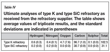
Material characterization and method development were reported in detail in a method development paper presented at EEC 2016, the 11th European Electric Steelmaking Conference and Expo (Banda, Steenkamp, and Matinde, 2016). The methods are summarized here for completeness. Bulk chemical compositions of three representative SiMn samples were determined by wet chemistry and X-ray fluorescence (XRF), and the carbon content of the alloy was determined using ultimate analysis (LECO instrument). The refractory material was subjected to chemical analysis to evaluate the concentrations of the elements present. The bulk chemical analyses included proximate (ASTM-D3172, 2013), ultimate, and ash analyses (ASTM-D3174, 2012).
Proximate analysis was done on the refractory samples; the moisture, ash, and volatile matter content were measured, and the fixed carbon was calculated by difference (ASTM-D3172, 2013). The moisture content of a sample was determined using a drying oven, with the moisture content being obtained by difference of the masses before and after drying (ASTM-D3173, 2011). Thermogravimetric analysis (TGA) was used to obtain the volatile matter content and ash content by noting the temperature variations which result in mass changes in the sample as the atmosphere changes from inert to oxidizing. Fixed carbon was determined by difference (Banda, Steenkamp, and Matinde, 2016). Lastly, ultimate analysis was done to obtain elemental analyses of the carbon-based refractory materials. The results from ultimate analysis were used to determine the composition of the refractory, including carbon, hydrogen, nitrogen, and sulphur. Oxygen was determined by difference (SGS, 2015).
Bulk phase chemical analysis was done using X-ray diffraction (XRD), which provided means of quantifying and characterizing different crystalline phases as well as the amorphous phases present. A Bruker D8 diffractometer with an acceleration voltage of 35 kV and cobalt tube with Fe-low beta filter was used with the 29 angle ranging from 2 to 80 degrees and a step size of 0.02° 29. Microscopic examination of the refractory was conducted using a Zeiss Evo MA15. The specific phase chemistry of different phases present in the refractory was characterized by scanning electron microscopy-energy dispersive spectroscopy (SEM-EDS) using an acceleration voltage of 20 kV, and electron microprobe analysis (EMPA) using an acceleration voltage of 15 kV (Banda, Steenkamp, and Matinde, 2016).
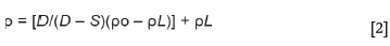
The bulk density of a porous material is the ratio of its mass to bulk volume (Baxendale, 2004), and was calculated using Equation [2]. The apparent porosity is the ratio of the open pores in the material to the bulk volume and was calculated using Equation [3]. The Archimedean evacuation method was used to measure both the bulk density and apparent porosity. A method based on ASTM standard C20-00, developed by Mushwana and Steenkamp (2015), was used as the standard measurement procedure.
where
p = Bulk density of the sample (g/cm3)
po= Density of auxiliary liquid (g/cm3)
pL= Density of air (taken as 0.0012 g/cm3)
P = [(W- D)/V] * 100

where
P = Apparent porosity (%)
W = saturated weight (g)
D = dry mass (g)
V = exterior volume (cm3), based on Equation [3]
V = W - S

FactSage™ thermodynamic calculations
FactSage™ thermodynamic software was used to predict the potential for chemical wear by one of the wear mechanisms applicable (Bale et al., 2016). The Equilib module in FactSage™ 7.2 was applied in thermodynamic calculations. The FeMn database developed by Tang and Olsen (2006) is known to be more reliable for SiMn/FeMn systems and was used together with the FactPS database. For the calculations the temperature was varied at 1550°C, 1600°C, and 1650°C and the Si content in the alloy was varied at 15, 16, and 17 mass % for both type K and type SiC refractory. Carbon solubility in Mn-Fe-Si-C alloys with a Mn:Fe mass ratio of 4.4 at 1550°C, 1600°C, and 1650°C was calculated with FactSage 7.2 (FactPs and FeMn or FSstel databases). 100 g SiMn and 100 g of each refractory was assumed, togehther with the as-received SiMn alloy composition reported in Table I.
Rotating finger experimental design
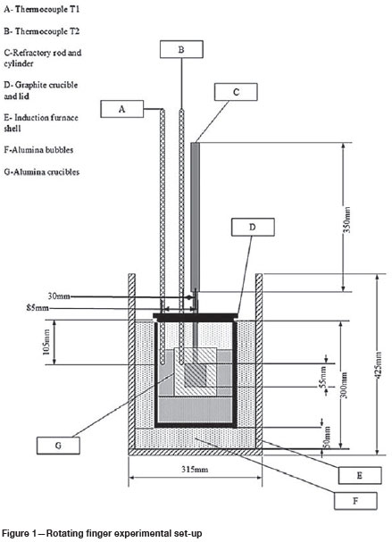
To further investigate the wear shown by thermodynamic calculations, a rotating finger experiment set-up was designed and built. Static and dynamic tests were carried out and the results compared to the thermodynamic calculations. Figure 1 shows the design of the experimental set-up. The refractory cylinder, with a diameter of 50 mm and a height of 55 mm, was attached to a cylindrical graphite rod with a height of 550 mm and diameter of 20 mm using graphite glue. The graphite rod was mounted onto an extension arm which was connected to the rotating motor. The graphite crucible (outer diameter 200 mm, height 250 mm) was placed inside the 25 kW induction furnace to facilitate heat transfer, and alumina bubbles was added between the crucible and the furnace chamber to achieve the required height and minimize energy losses to the environment. The alumina crucible (outer diameter 100 mm, height 115 mm) was placed inside the graphite crucible with alumina foam to obtain the required height inside the graphite crucible. The SiMn alloy and refractory cylinder interacted inside the alumina crucible when the operating temperature was reached. B-type thermocouples were used to measure the temperature inside the furnace.
The variables in the experiments were temperature, mass per cent Si in the alloy, and rotational speed. The fixed variables included reaction time, which was maintained according to the Mintek standard operating procedure for induction furnace tests (90 minutes). The heating rate was also based on the Mintek standard operating procedure, and was manually adjusted at increments of 0.5 A every 30 minutes. The reaction chamber was purged with argon to maintain an inert atmosphere. The controlled variables are listed below. When the influence of a specific variable on refractory wear was evaluated, all other variables were fixed at the baseline value.
1. The temperature was varied between 1550 and 1650°C, at 50°C intervals. The baseline value for temperature was 1600°C. These values represent the typical temperatures for SiMn producing furnaces.
2. The Si content of the alloy was varied between 15, 17, and 18 mass %. The baseline value was 15 mass %. The SiMn composition of the alloy was below grade B, which is normally produced by the local SiMn producer, thus the values chosen cover the composition of the characterized alloy, as well as those specified by the ASTM standard for grade B (ASTM A483, 2010).
3. The motor speed was set at either zero (static) or 100 r/min (dynamic). Zero was chosen to allow better comparison with thermodynamic calculations and 100 r/min was chosen as it was the best maximum speed that resulted in good alignment of the graphite rod, and allowed mechanical wear to be investigated.
Results and discussion
Material characterization
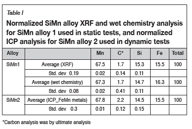
Figure 2a and 2b show the as-received SiMn alloy and the corresponding SEM BSE image. The bulk chemical composition of the SiMn alloy 1, which was used for the mechanical equipment testing and static tests, is reported in Table II and Table II. Table I also shows the bulk chemical composition for SiMn alloy 2 used for the dynamic tests.
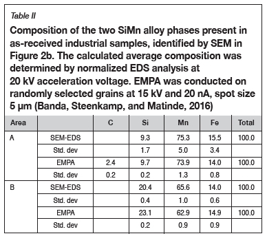
Phase chemical analysis of the SiMn alloy revealed that there were two phases present (Figure 2b). The two phases can be distinguished by a light grey area (A) and a dark grey area (B). SEM-EDS and EMPA result in Table II indicate that phase A is a high-Mn and low-Si phase, while phase B is a high-Si phase with lower Mn levels relative to phase A. The presence of carbon was also identified in phase A.
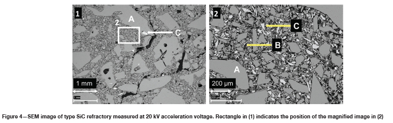
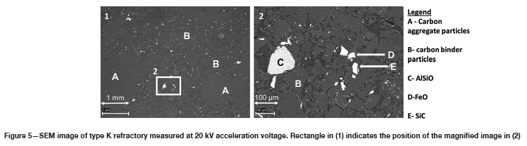
Figure 3a (1 and 2) shows the as-received type SiC refractory. The corresponding SEM-BSE image can be seen in Figure 4. SiC occurs as the major phase, with Si oxide and Si present as minor phases. Figure 3b (1 and 2) shows the as-received type K refractory, and the corresponding SEM-BSE image is shown in Figure 5. The type K refractory contains a major carbon phase, which consists of carbon aggregate and binder particles, as well as minor intrusions (25 urn length x 30 urn breadth) of SiC and FeO particles which may have resulted from surface contamination when the samples were prepared at Elkem.
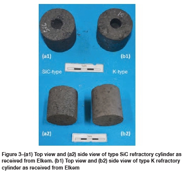
Table III and Table IV list the proximate and ultimate analyses of the as-received refractory samples.
Density and porosity measurement results for the two refractory samples are presented in Table V. The average measured density values are in line with the values supplied by the manufacturer's data-sheets (Elkem Carbon, 2009, 2015). The calculated porosity value for type K refractory is also comparable to that given by the manufacturer. A comparison of the bulk densities of the two refractories shows that for a given volume, type SiC refractory will have a larger mass than type K refractory; also that porosity is directly proportional to bulk density and inversely proportional to true density, as seen in Equation [5] (Mushwana and Steenkamp, 2015). It can also be seen from Table V that the porosity of type SiC refractory is 1.3 times greater than that of type K refractory.

Refractory wear under different laboratory conditions
Effect of temperature
The SiMn alloy composition in Table I was used to calculate C solubility in Mn-Fe-Si-C alloys with a Mn:Fe mass ratio of 4.4 at 1550°C, 1600°C, and 1650°C, using FactSage 7.2™ in conjunction with FSstel, FactPS, and the FeMn database developed by Tang and Olsen (2006), as shown in Figure 6. Compositions are given as mass percentages. The as-received alloy was unsaturated in both C and SiC and thus will tend to dissolve both C and SiC refractories. For Si mass percentages below the dual saturation point on the curve, the stable solid phase at saturation is graphite. SiC is the stable phase at saturation for higher Si contents. It can be seen in Figure 6 that the solubility of C increases with increasing temperature from 1550°C to 1650°C, and thus it is expected that wear in both refractories would increase with increasing temperature.
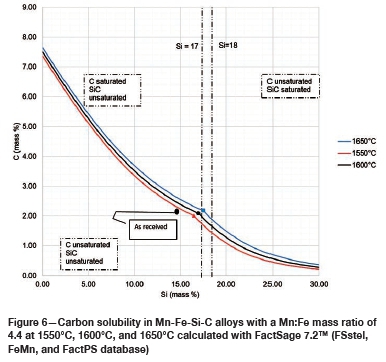
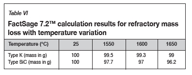
Table VI contains the FactSage™ calculation results. It was shown that both refractories would dissolve into the alloy as the temperature increased. The calculations also show that type SiC would experience more mass loss than type K. In Figure 6 it can be seen that increasing the temperature from 1550°C to 1650°C at a constant Si content of 14.5 mass % will result in the dissolution of type K refractory until the alloy is C-saturated, and as the temperature increases type K will dissolve further into the alloy. On the other hand, at a constant Si content of 14.5 mass %, the alloy remains SiC-unsaturated and thus type SiC experiences more mass loss due to dissolution into the alloy.
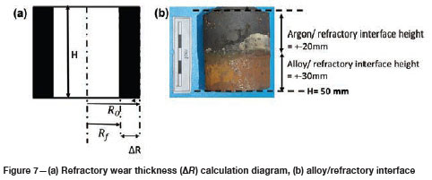
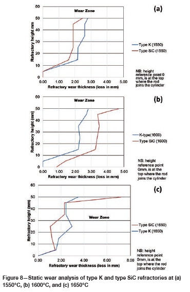
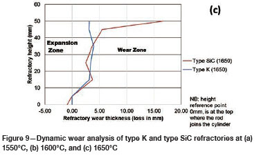
To quantify the loss in refractory thickness due to wear (ΔR), the refractory diameter was measured before (RO) and after (Rf) the experiments, and the difference was plotted against refractory height (Figure 7a). The alloy/refractory interface was around 30 mm in height and the argon gas/refractory interface around 20 mm (Figure 7b). When only the temperature was varied and the Si content kept constant at 14.5 mass %, the experimentally determined static refractory wear profile (Figure 8) and the dynamic wear refractory wear profile (Figure 9) were found to agree with the FactSage™ prediction. In Figure 9b and 9c, 'negative refractory wear' can be seen; this was due to refractory expansion caused by the alloy infiltrating the refractory along with the refractory height. It can also be seen that the type SiC refractory surface (on the 50 mm plane) in contact with the alloy lost a greater thickness than type K refractory on the same plane. The results presented In Figure 8a are contradictory, and this deviation could have been introduced by the measurement relative error of 1.69 % on type SiC refractory.
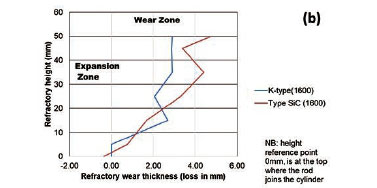
Varying the rotational speed from zero (static) to 100 r/min (dynamic) at constant Si content and temperature (Figure 10) resulted in more wear in type SiC refractory than type K. The dynamic motion introduced erosion wear, but the effect was not as significant as chemical wear. To further allow comparison of infiltration depth, both refractories were selected at static conditions, at a temperature of 1600°C and Si content of 15 mass %. In Table V it can be seen that type SiC refractory had a higher porosity value (23%) than type K (18%), thus making type SiC refractory more susceptible to alloy infiltration. The observations are in line with studies conducted to understand the relationship between refractory characteristics and corrosion wear mechanism, which have revealed that porosity plays a significant role in promoting infiltration, thus increasing corrosion (Brosnan, 2004; Bazan et al., 2011).
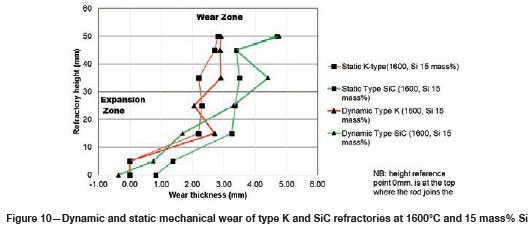
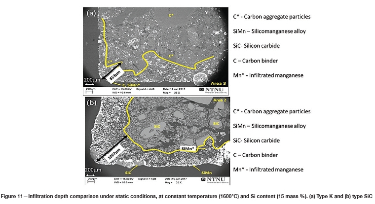
SEM analysis of the two refractories at 200 urn scale (Figure 11) shows that type SiC refractory allowed greater alloy infiltration depth (1087 μm), resulting in refractory expansion, while erosion of type K refractory was more surfacial with an infiltration depth of 653 μm. Increased alloy infiltration can also be identified from the white areas in the SEM images, where for type SiC (Figure 11b) there is more white area (alloy phase) compared to type K (Figure 11a). At static conditions, both type K and type SiC refractory had alloy infiltration depths greater than 100 μm when the temperature was varied. Alloy infiltration depths of above 100 um were also observed by Brosnan, (2004).
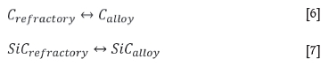
Overall, at a constant temperature of 1600°C and 14.5 mass % Si , type SiC experienced more wear than type K due to the alloy being SiC-unsaturated, and to a lesser extent due to the motion of the refractory. The dissolution reaction taking place in type K is C dissolving into the alloy phase (Equation [6]), and for type SiC, SiC dissolving into the alloy phase (Equation [7]).
Effect of Si content
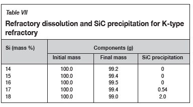
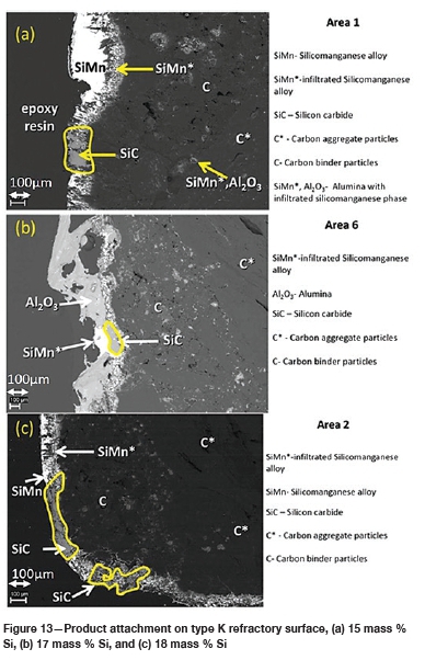
The FactSage™ calculations in Table VII show a decrease in mass loss for type K refractory with an increase in alloy Si content from 14 mass % to 16 mass % Si, but the mass loss increased again, with increasing precipitation of SiC product, at 17 and 18 mass % Si. The wear profile analysis on type K refractory (Figure 12) revealed that the wear increased with increasing Si content from 14.5 to 17 mass %, then decreased at 18 mass % Si, contrary to the FactSage™ calculations. In Figure 6 it can be seen that C solubility decreases with increasing Si content in the alloy; the alloy is unsaturated in C and thus increasing the Si content from 14.5 to 17 mass % resulted in decreased solubility of C in the alloy. The alloy still dissolved type K refractory until saturation was reached, and at the dual saturation point SiC was precipitated. Further increasing the Si content to 18 mass % resulted in a SiC-saturated alloy. In this region, SiC was precipitated and type K refractory was expected to dissolve further since the alloy is C-unsaturated. There is a possibility that the precipitated SiC formed a protective layer around the refractory, hence the reduction in wear at 18 mass % Si (Lee, Argent, and Zhang, 2002; Lee and Zhang, 2004). SiC precipitated from SiMn alloy on type K refractory at various Si contents can be seen in the SEM micrographs in Figure 13.
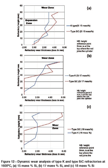
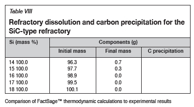
The FactSage™ calculations in Table VIII show that the mass loss for type SiC refractory would decrease with increasing Si content and that C would be precipitated at 14 and 15 mass %. Si. Precipitation of C would decrease with increasing Si content. In Figure 12 it can be seen that type SiC refractory wear area increased with increasing Si content from 14.5 to 18 mass %. At a constant temperature of 1600°C and 17 mass % Si, C and SiC are at dual saturation (Figure 6), thus wear from dissolution is not expected. At 1600°C and 18 mass % Si, the alloy is SiC-saturated and C-unsaturated and thus type K refractory was expected to undergo more dissolution, and none was expected for type SiC refractory. Experimentally, it was found that type SiC wore more than type K; this was mostly due to the physical properties of type SiC, such as high porosity, which resulted in preferential attack on the carbon binder.
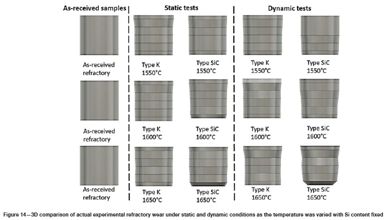
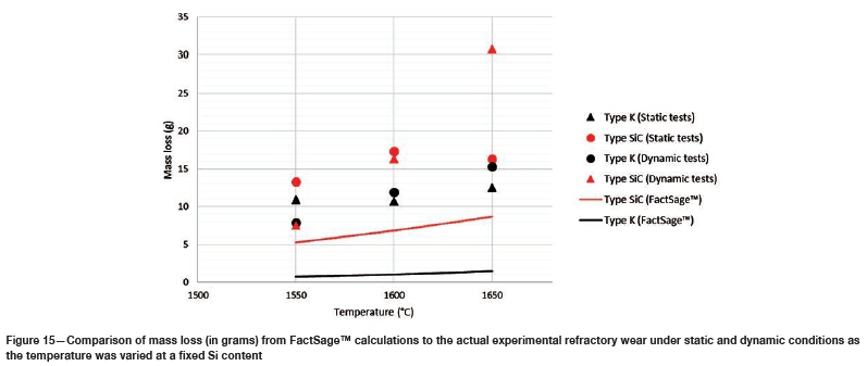
Post-mortem refractory sample diameter was measured and the volume loss at various temperatures was calculated using 3D modelling on Autodesk Fusion 360 3D CAD/CAM design software (Figure 14). The volume was then converted to mass loss to compare with the FactSage™ results (Figure 15). FactSage™ mass loss data was then recalculated with the same initial mass of the as-received type K and type SiC samples; 145.29 g and 228.15 g respectively.
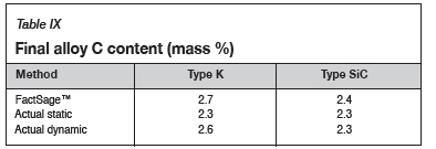
Using the calculated mass to compare the experimental and thermodynamic calculations results, it can be observed in Figure 15 that the refractory mass loss due to wear in the experimental tests was greater than that shown by the FactSage™ calculations, due to the preferential attack on the binder phase and resultant loss of structural integrity. FactSage™ also does not take into account the kinetics of the chemical reactions taking place, the physical properties of the refractories such as porosity, nor fluid dynamics. The deviation in total mass was therefore expected, but the general refractory behaviour from the thermodynamics point of view was expected to agree, and this can be observed in Table IX, where the carbon dissolution into the alloy calculated using FactSage™ at 1550°C and 15 mass % Si was found to agree with the experimental results .
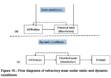
Wear mechanism in type K and type SiC refractories
The predominant wear mechanisms at static conditions for both refractories (Figure 16a) were infiltration and chemical wear by dissolution. At dynamic conditions (Figure 16b) wear was by infiltration, chemical dissolution, and erosion. The main wear mechanism was chemical wear as it was shown that erosion had a minor impact on the overall mechanical wear at constant temperature and composition. These observations are in line with the results of Lee, Argent, and Zhang (2002), Jansson, Brabie, and Bohlin (2004), Lee and Zhang (2004), and Steenkamp (2014).
Refractory suitability for use in the hearth area of an industrial SiMn furnace
The study sought to investigate the wear mechanisms of type K and type SiC refractories under different laboratory conditions and their suitability for use in the hearth area of an industrial furnace producing SiMn alloys. Table X summarizes the conclusions from the investigation. For Mn-Fe-Si-C alloys with a Mn:Fe mass ratio of 4.4 the findings are as follows:
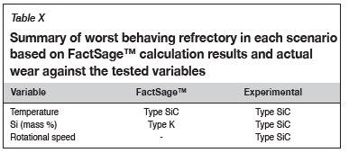
> At various temperatures and constant Si content at 14.5 mass %, type SiC refractory experienced more wear than type K. Increasing the temperature at constant Si content resulted in the alloy becoming C-saturated and SiC-unsaturated.
> With varying Si content and a constant temperature of 1600°C, type K refractory was expected to experience more wear, and when the alloy was SiC-unsaturated type SiC was expected to experience more wear. Experimentally, type K behaviour was contradictory as the alloy experienced less wear, which could be attributed to the SiC product forming a protective layer that inhibited further refractory wear. The behaviour of type SiC was also contradictory, and this was due to physical properties such as porosity, which allowed the alloy to preferentially attack the carbon-based binder, thus promoting refractory disintegration.
> When the rotational speed was varied from static to dynamic at constant Si content and temperature, type SiC refractory experienced more wear than type K. The effect of mechanical wear was not as significant as chemical wear.
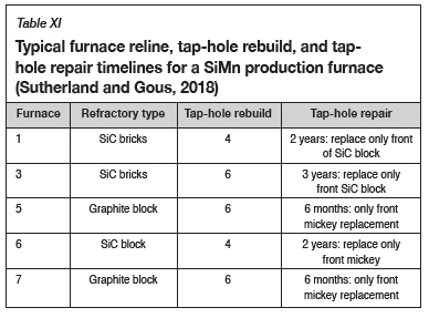
In summary, type K refractory is better suited for use in the hearth area of an industrial furnace provided that the Si content of the alloy is below 17 mass %. Also, the physical properties of type K refractory, such as low porosity and bulk density, make the refractory more versatile by limiting infiltration to the surface. Table XI shows that the observations made in this study are similar to what was observed in the tap-hole areas of five industrial furnaces producing SiMn alloy (Sutherland and Gous, 2018). The carbon-based refractories (graphite) generally lasted 1.2 times longer than the SiC-based refractories in the tap-hole.
Conclusion
Thermodynamically, the alloy was not saturated in either C or SiC, and hence it was expected that both type K and type SiC refractories would dissolve into the alloy. Using FactSage™ it was shown that the predominant wear mechanism for both refractories at the temperatures employed was chemical wear, with type SiC experiencing the most wear. Increasing temperature at a constant Si content of 14.5 mass %, the alloy reached saturation but temperature increases above 1550°C resulted in increased C solubility into the alloy. At a constant Si content of 14.5 mass % the alloy remained SiC-unsaturated, hence type SiC refractory was expected to wear the most. Experimentally, it was also found that type SiC experienced more wear than type K refractory. Microscopic examination revealed greater infiltration into type SiC refractory because of its porous nature, promoting more chemical wear by dissolution compared to type K, where refractory wear occurred on the surface.
Using FactSage™ it was shown that both refractories would undergo wear when the Si content was varied. The mass loss was due to chemical wear by dissolution, with type SiC experiencing the most wear. Increasing the Si content at a constant temperature of 1600°C resulted in a decrease in C solubility, and a further increase in the Si content from the dual saturation point, from 17 to 18 mass %, resulted in the alloy being C-unsaturated and SiC-saturated. Experimentally it was found that type SiC refractory experienced more wear than type K, which contradicted the FactSage™ results. Microscopic examination revealed greater infiltration into type SiC refractory because of its porous nature and preferential attack on type SiC carbon binder. Chemical wear was experienced by type K, with SiC precipitated on the refractory surface.
Type K refractory was found to be the most suited material for use in the hearth area of an industrial furnace, provided that the Si content of the alloy is maintained below 17 mass % for Mn-Fe-Si-C alloys with a Mn:Fe mass ratio of 4.4. This observation is in agreement with what has been found in industry, where carbon-based refractories generally last 1.2 times longer than SiC-based refractories in the tap-hole. The main wear mechanism was chemical wear by dissolution. Erosion was introduced with dynamic motion, but the effect was insignificant compared to the chemical reaction.
Acknowledgements
This paper is published with the permission of Mintek. The authors would like to acknowledge Transalloys and Elkem Carbon for technical support.
References
ASTM-D3172. 2013. Standard practice for proximate analysis of coal and coke 1. Annual Book of ASTM Standards. ASTM International, West Conshohocken, PA. pp. 1-2. doi: 10.1520/D3172-13.2 [ Links ]
ASTM-D3174. 2012. Standard test method for ash in the analysis sample of coal and coke from coal 1. Annual Book of ASTM Standards. ASTM International, West Conshohocken, PA. pp. 1-6. doi: 10.1520/D3174-11.2 [ Links ]
ASTM-D3173. 2011. Standard test method for moisture in the analysis sample of coal and coke 1. Annual Book of ASTM Standards. ASTM International, West Conshohocken, PA.: pp. 1-4. doi: 10.1520/D3173-11.2 [ Links ]
ASTM A483. 2010. Standard specification for silicomanganese. Annual Book of ASTM Standards. ASTM International, West Conshohocken, PA. pp. 1-2. doi: 10.1520/F1026-86R08E01.2 [ Links ]
Bale, C.W., Bélisle, E., Chartrand, P., Decterov, S.A., Eriksson, G., Gheribi, A.E., Hack, K., Jung, I.H., Kang, Y.B., Melançon, J., Pelton, A.D., Petersen, S., Robelin, C., Sangster, J., Spencer, P., and van Ende, M-A. 2016. FactSage thermochemical software and databases - 2010 - 2016. Calphad, vol. 54. pp. 35-53. [ Links ]
Banda, W., Steenkamp, J.D., and Matinde, E. 2016. Chemical wear of carbon and silicon carbide-based refractory materials by silicomanganese metal. EEC11 - Proceedings of the 11th European Electric Steelmaking Conference & Expo, Venice, Italy, 25-27 May 2016. Associazione Italiana di Metallurgia. [ Links ]
Bazan, J., Socha, L., Martínek, L., Fila, P., Balcar, M., and Chmela, J. 2011. Wear of refractory materials for ceramic filters of different porosity in contact with hot metal. Materials and Technologies, vol. 45, no. 6. pp. 603-608. [ Links ]
Brosnan, D.A. 2004. Corrosion of refractories. Refractories Handbook. Schacht, C.A. (ed.). Marcel Dekker, New York. pp. 39-77. https://www.jurispro.com/files/documents/doc-1066205184-article-1609.pdf [ Links ]
Chesters, J.H. 1963. Refractories Production and Properties. The Iron and Steel Institute, London, UK. [ Links ]
Dzermejko,A.J., Baret, D.F., and Hubble, D.h. 1999. Ironmaking refractory systems. Making, Shaping and Treating of Steel - Ironmaking Volume. ASM International, Materials Park, OH. pp. 229-258. [ Links ]
Elkem Carbon. 2015. Type K lining paste, data sheet. Kistiansand, Norway. [ Links ]
Elkem Carbon. 2009. Elkem cold lining paste type-SiC, data sheet. Kistiansand, Norway. [ Links ]
Ewais, E.M.M. 2004. Carbon based refractories. Journal of the Ceramic Society of Japan, vol. 112, no. 10. pp. 517-532. doi: 10.2109/jcersj.112.517 [ Links ]
Hancock, J. 2006. Practical Refractories. Cannon and Hancock, Vereeniging, South Africa. [ Links ]
Jansson, S., Brabie, V., and Bohlin, L. 2004. Corrosion mechanism and kinetic behaviour of refractory materials in contact with CaO-Al2O3 -MgO-SiO2 slags. Scandinavian Journal of Metallurgy, vol. 34, no. 5. pp. 341-348. [ Links ]
Lee, W.E., Argent, B.B., and Zhang, S. 2002. Complex phase equilibria in refractories design and use. Journal of the American Ceramic Society, vol. 85, no. 12. pp.2911-2918. [ Links ]
Lee, W.E. and Zhang, S. 2004. Direct and indirect slag corrosion of oxide and oxide-c refractories. Proceesings of the VII International Conference on Molten Slags, Fluxes and Salts, Cape Town. Southern African Institute of Mining and Metallurgy, Johannesburg. pp. 309-320. [ Links ]
Mattila, R.A., Vataneen, J.P., and Härkki, J.J. 2000. Chemical wearing mechanism of refractory materials in a steel ladle slag line. Proceedings of the VI International Conference on Molten Slags, Fluxes and Salts, Stockholm. https://www.pyrometallurgy.co.za/MoltenSlags2000/pdfs/159.pdf [ Links ]
M0LNÂS, H. 2011. Compatibility study of carbon-based refractory materials utilized in silicomanganese production furnaces. Master's dissertation, Norwegian University of Science and Technology. [ Links ]
Mushwana, M. and Steenkamp, J.D. 2015. Apparent porosity and bulk density measurements of samples from an industrial-scale Söderberg electrode. Mintek, Randburg, South Africa. [ Links ]
Routschka, G. and Wuthnow, H. (eds). 2008. Refractory Materials: Pocket Manual : Design, Properties, Testing. Vulkan, Essen. [ Links ]
SGS. 2015. Proximate and ultimate analysis - Mining. http://www.sgs.co.za/en/Mining/Analytical-Services/Coal-and-Coke/Proximate-and-Ultimate-Analysis.aspx [accessed: 1 July 2015]. [ Links ]
Steenkamp, J.D. 2014. Chemical wear of carbon - based refractory materials in a silicomanganese furnace tap-hole. PhD thesis, University of Pretoria. [ Links ]
Tang, K. and Olsen, S.E. 2006. Computer simulation of equilibrium relations in manganese ferroalloy production. Metallurgical and Materials Transactions B, vol. 37. pp. 599-606. [ Links ]
Tomala, J. and Basista, S. 2007. Micropore carbon furnace lining. Innovation in Ferroalloy Industry: Proceedings of Infacon XI, New Delhi, India, 18-21 February 2007. Indian Ferro Alloy Producers' Association. pp. 722-727. [ Links ]
 Correspondence:
W.K. Banda
Email: bandawesley@gmail.com
Received: 9 Oct. 2019
Revised: 9 Apr. 2020
Accepted: 15 May 2020
Published: May 2020

