


Services on Demand
Article
 English (pdf)
 Article in xml format
 Article references
Indicators

Related links
-
 Cited by Google
 -
 Similars in Google
Share

 Permalink
Journal of the Southern African Institute of Mining and Metallurgy
On-line version ISSN 2411-9717
Print version ISSN 2225-6253
J. S. Afr. Inst. Min. Metall. vol.120 n.4 Johannesburg Apr. 2020
http://dx.doi.org/10.17159/2411-9717/955/2020
ARTICLES
Tensile strength sensitivity of thin spray-on liners to changes in environmental conditions
M.J. Kanda; T.R. Stacey
University of the Witwatersrand, South Africa
SYNOPSIS
Thin spray-on liners (TSLs) are an areal support with the perceived ability of promoting rock mass stability, based on their high tensile strength and elongation capacity. However, these benefits are not always realized in the mining environment, which has resulted in some scepticism regarding the utilization of TSLs. The research described in this paper was carried out to measure the tensile strengths of TSLs after they had been subjected to underground-like conditions. This was achieved by exposing prepared samples to three environmental conditions: a 'standard' room-temperature and humidity condition; a saturated room-temperature condition; and a saturated, high-temperature (50°C) condition. Periods of exposure extended up to 112 days. The test results showed that humidity and temperature have an adverse impact on TSL uniaxial tensile strength, deformation modulus, and elongation. Some TSLs available commercially may therefore completely underperform in humid and higher temperature conditions, and some even under normal laboratory conditions. Water-based TSLs indicate good suitability for use in humid conditions, but their performance declines when higher temperatures are involved. Therefore, it is inappropriate to design underground support systems using TSLs based on strength and deformation properties determined under normal laboratory conditions.
Keywords: areal support, thin spray-on liner, TSL, tensile strength, UTS.
Introduction
Geotechnical hazards in underground mines are closely linked with rock-related accidents (Kuijpers et al, 2004; Potvin, Stacey, and Hadjigeorgiou, 2004; Szwedzicki, 2003). In 2017, 88 fatalities were recorded in the South African mining environment, and the major cause was reported to be related to rockbursts (Minerals Council South Africa, 2018). Rockfalls were the second major cause, though commonly thought to be the major cause. Significant efforts have been made to mitigate geotechnical risks in the past decades. Such efforts include the continual improvement of mining support systems that can retain and contain the rock mass. Among the containing supports, also called areal supports, are wire mesh, straps, mortar, shotcrete, etc. (Hoek, Kaiser, and Bawden, 2000). Another type of mining support that has emerged in the last few decades is a thin membrane for surface support called a thin spray-on liner (TSL).
This areal support has also been referred to as a thin sprayed membrane, multi-component polymeric liner, thin coating material, or just a thin liner. It has been promoted as possessing higher tensile strength than traditional shotcrete support, and as being capable of spanning large cracks in the rock mass, thus limiting the movements of mobilized rocks (Tannant, 2001). Tensile tests on rocks and shotcrete specimens by Mpunzi et al. (2015) showed that, depending on the TSL used, the tensile strength of a strong, brittle rock can be increased by some 30%, and that of shotcrete by more than 40%. However, these benefits are not always realized in the mining environment, despite the extensive number of laboratory tests promoting the beneficial properties of TSLs (Kanda and Stacey, 2019). To date, laboratory tests on TSLs have apparently been performed mainly under room temperature and humidity conditions, which are generally not the ambient conditions in which TSLs are applied. In South Africa, TSLs are often applied in mines characterized by high temperature and humidity, particularly when it comes to deep mines, but no references to testing under such conditions were found. Therefore, there is a need to research their true characteristics by testing TSLs under conditions similar to those encountered in underground mines. A review of liner support mechanisms identified nine such mechanisms, at least six of which depend significantly on the tensile strength contribution of the liner (Mpunzi et al, 2015). In addition, theoretical analyses indicated that tensile strength of TSLs provides their greatest contribution to rock support (Stacey and Yu, 2004). Therefore, since tensile strength is such an important mechanical property of thin coating materials, the research described in this paper focused on evaluating TSL uniaxial tensile strength (UTS) behaviour after exposure to humidity and high temperature (50°C). As the exposure time is also an important parameter in the assessment, the samples were exposed to these underground mine-like conditions for periods of up to 112 days. The results obtained are compared with those from tests performed on specimens stored in 'room' conditions, under which TSLs have commonly been tested to date. And for this particular condition, though a hygrometer was used to check on the room-temperature behaviour, which generally ranged between 22°C and 26°C, no effort was made to keep it steady since it had to reflect the conditions of most TSL tests, generally performed with no particular focus concerning its fluctuation.
Effect of temperature and humidity on polymeric materials
The mechanical behaviour of polymeric materials, such as TSLs, is related to time and temperature (Findley and Davis, 2013; Guner and Ozturk, 2018). Osswald (2015) suggested that polymeric material behaviour over time is temperature-related and could be explained through the Boltzmann superposition principle. Osswald explained that high-temperature conditions shorten the time of molecular relaxations while low-temperature conditions extend the relaxation time, with these temperatures not affecting the shapes of the stress relaxation curves. This supports the motivation for the current study to assess the performance of polymer-based liners under various temperature conditions. In this investigation, uniaxial tensile strength (UTS) laboratory tests were carried out on three TSLs.
Laboratory testing
TSL characteristics
Samples of TSLs from three different manufacturers were assessed and were coded as TSL1, TSL2, and TSL3 for confidentiality. Their compositional characteristics are provided in Table I.
> TSL1 is a cementitious product mixed with additives. The raw material is supplied as three components that are to be mixed: cement, polymer, and sand. The final product is expected to prevent unravelling and oxidation of rock as well as to provide lateral constraint to rock masses.
> TSL2 is a cementitious material, the raw material being supplied in a bag as a single-component powder, and clean tap water is used to form the mixture.
> TSL3 is a plasticizer-free aqueous copolymer emulsion composed of acrylic acid esters and wetting agents mixed with a cementitious binder. The final product is nonflammable and non-toxic. It is claimed to be able to bond to dusty, wet, and greasy surfaces.
These three TSLs were chosen for testing since they have been used in substantial quantities in the gold and platinum mines of South Africa. Their continued use in such conditions is indicative of the fact that they have been considered to have provided benefit.
Specimen preparation
Dogbone-shaped specimens were prepared for tensile testing according to ASTM D-638, 2010 type I, the design of which is depicted in Figure 1. The shape of a dogbone type IV, which is more appropriate for plastic materials, is also shown in Figure 1.
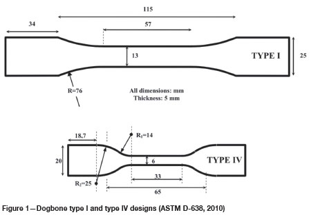
Guner and Ozturk (2018) recommend the preparation of dogbone shaped specimens using die-cutting since it results in higher maximum tensile strengths, with smaller standard deviations, than for specimens made using moulds. However, their recommendation is appropriate for ductile TSLs rather than brittle liners, which are the focus of the current research. In this research, great care was taken in the preparation process, during the pouring and removal of the specimens, in order not to alter their texture or integrity.
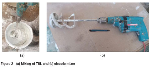
All the specimens were prepared under 'room' environmental conditions (temperature: 23±2°C) using an electric mixer illustrated in Figure 2.
For representativeness, three sets of samples were prepared (75 specimens per set/mixture, resulting in 25 specimens allocated to each environmental condition). Although it is advisable to prepare a complete set of TSL specimens in a single step, this was not possible due to the limited capacity of the mixing equipment, the large number of specimens required, and the diversity of the tests. A further constraint was that some TSLs, such as TSL1, could begin to set before reaching the required mature texture, especially when large volumes were prepared. Therefore, only solid constituents to a maximum of 2 kg could be prepared per batch according to the manufacturer's recommended instructions. The preparation process was therefore repeated and preliminary testing (one to five days) was performed to validate the consistency of the textures and the strengths. In most of the cases, the preliminarily assessed strengths were satisfactory.
For all the TSLs, the specimen preparation steps were as follows:
1. Apply a very thin film of release agent on all the parts of the mould sets to avoid sticking of the TSL onto the mould.
2. Assemble every mould part and place the sets on a flat working surface covered with a plastic film. This film helped to prevent direct contact between the thin liner and the working surface, and therefore to avoid damaging the liner when removing the specimen.
3. Mix the constituents of the TSL packages according to the instructions provided by the manufacturers.
4. Pour the TSL mixture into the moulds and spread it out using a spatula, making sure that it fills the mould set.
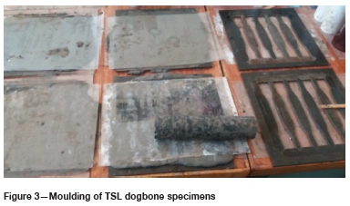
5. Use a plastic film to cover the mixture and gently level it down by rolling a rock core over the set to ensure the moulding set thickness of 5 mm, as shown in Figure 3.
6. Wait for two to three days for the TSL to set before isolating the mould elements and removing the TSL specimens (for short-term tests, removal could be after one day or even shorter, but the testing was focused on longer term curing).
7. Use the sharp part of the spatula to remove the excess TSL around the dogbone shape that could prevent the specimen from being in full contact with the grips during the testing phase.
In practice, the thickness of the moulded specimens varied between 4 mm and 6 mm, while the width ranged between 12 mm and 14 mm. After the moulding process, the specimens were kept in the moulds for three days to set properly. These specimens were then split into three groups. One group was stored under normal room conditions (R), the second group in a container full of tap water at ambient temperature (H), and the third group was placed in a water container and stored in an oven at 50°C (HT). It is acknowledged that such 100% saturation is an extreme case - it was used since it was much easier to implement than to attempt to achieve a particular saturation percentage. Since this study's focus was on the evaluation of the UTS of TSL specimens exposed to high temperature and humidity conditions to simulate mining conditions, exposure times of 15, 28, 56, and 112 days were used. Thereafter, the tensile strengths were measured in the laboratory tests.
Test set-up
The testing process follows the prescribed method recommended by ASTM D-638 (2010), with a few modifications suggested by Yilmaz (2010). The testing machine used for the UTS testing for all the specimens was the MTS model 643.15A-03, shown in Figure 4a. This multi-functional machine is equipped with a 10 kN load cell for UTS tests. Care was taken to ensure that the specimens were centred and well-adjusted in the grips when the tests were performed. A preload of about 15 N was applied to allow the test to start at the loading rate of 5 N/s until failure occurred (Yilmaz, 2010). A test result was considered valid only if the specimen failed at its narrow section (Yilmaz, 2010). The UTS tests were performed on dogbone specimens of three different TSLs that had been exposed to different environmental conditions for 15, 28, 56, and 112 days. The duration of exposure had to be longer than the traditional 28 days of curing. However, the specimens were also tested after the shorter exposure for the traceability of the strength results. A stress-displacement curve, represented by the example in Figure 4b, was the typical output for all the tests.


The tensile strength was calculated as follows:

where
σt= Tensile strength (MPa)
F = Tensile load at failure in newtons (N)
A = Specimen's cross-sectional area at the narrow section before test, in square millimetres (mm2)
σtrepresents the UTS of the TSL. From the stress-displacement curve, a stress-strain curve was deduced to evaluate the strain at failure, elongation, and Young's modulus. The strain was considered as the ratio of a recorded displacement to the initial distance between the grips. This initial distance was almost constant and equivalent to 70 mm.
Results
A view of some of the specimens tested is shown in Figure 5.
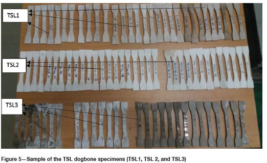
For the specified environmental condition, each batch of specimens contained at least 25 specimens, divided into the four exposure time tests. Therefore, at least six specimens were allocated to each TSL's exposure time.
TSL UTS sensitivities to environmental conditions
The UTS test results show the sensitivity of TSL tensile strength to various environmental conditions, as presented in Figure 6.
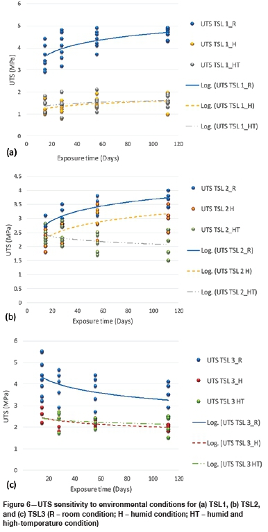
The results for TSL1 and TSL2 for room conditions show a strengthening trend with exposure time; but, in contrast, TSL3 showed a weakening trend. The reason for this cannot be explained. It is to be noted that the tensile strengths obtained for TSL1 and TSL3 after 28 exposure days were lower than the respective values of 9.7 MPa and 9.75 MPa indicated by the manufacturers. The measured strength of 3.2 MPa for TSL2 agreed well with the manufacturer's value of 3.1 MPa. The tests under different environmental conditions showed that TSLs exposed to saturated and higher temperature conditions, corresponding with some deep mining environments, have lower strengths than under room conditions. Their rates of strength increase with time are also lower, or may even become negative. An exception is the water-based TSL2, which shows a higher strength increase with time in saturated conditions, similar to its performance in room conditions. Overall, the negative influence of H (humid) and HT (humid and higher temperature) conditions on TSL UTS performance, as indicated by the laboratory tests, might be one of the reasons behind the perceived underperformance of TSLs in the mining sector (Kanda and Stacey, 2019), and the resulting scepticism regarding their utilization.
Influence of environmental conditions on TSL elongation and modulus
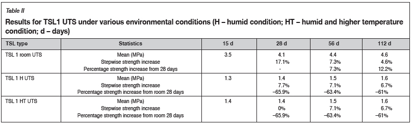
According to Guner and Ozturk (2018), TSL strength and modulus are proportional to curing time, and inversely proportional to elongation under normal laboratory (R) conditions. This was confirmed by the present research. Additionally, investigations were carried out to assess whether this conclusion is valid when liners have been exposed to different environmental conditions. To evaluate this, representative strength-deformation curves were considered, based on the average strengths of the three TSLs, which are summarized in Tables II, III, and IV. These tables also present the percentage strength increases relative to the conventional 28-day exposure/curing period.
The results for room environmental conditions, which show TSL strengthening over time, except for TSL3, confirm the information from the literature. However, the ultimate strengths for TSL1 and TSL2 were achieved beyond the 'conventional' 28 days. Therefore, for the three TSLs tested, it was observed that the strength at 14 days does not necessarily represent about 90% of the ultimate strength as stated by Guner and Ozturk (2018). In effect, if the ultimate strength is at 28 days, the strengths at 14 days for TSL1 and TSL2 correspond to 85% and 88%, respectively. These ratios drop to 76% of the strength at 112 days. A comparative study of the percentage strengths after 112 days of exposure in R and H conditions shows a decrease of H strengths of TSL1, TSL2, and TSL3 in the order of 65%, 16%, and 41%, respectively. Likewise, the strengths of TSL1, TSL2, and TSL3 from HT conditions decreased in relation to their corresponding R strengths after 112 days, in the order of 65%, 43%, and 35%, respectively.
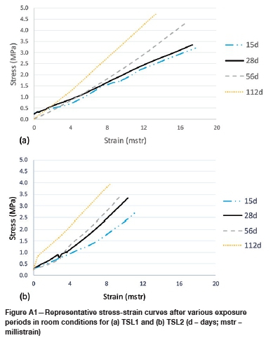
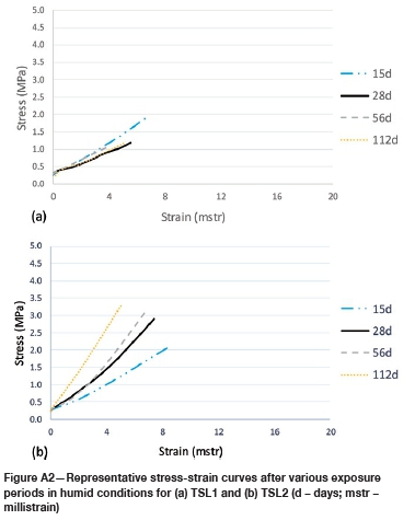
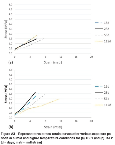
Figures A1, A2, and A3 in the Appendix show representative stress-strain curves determined from the average strengths of TSL1 and TSL2 after exposure to various environmental conditions. From these curves, the strains at failure and the moduli were extracted and plotted as presented in Figures 7, 8, and 9. The strains at failure were extracted directly from the curves, and moduli were calculated from the tangents to the stress-strain curves at 50% of the maximum stresses (Hudson and Harrison, 2000). These parameters were assessed for TSL1 and TSL2 after exposure to the various environmental conditions, TSL3 being omitted since its results, displayed in Table IV, show its limitation regarding its tensile strength performance. Figure 7 presents the behaviours of TSL1 and TSL2 under room environmental conditions, and confirm the correspondence of UTS and modulus with curing time in room conditions mentioned by Guner and Ozturk (2018).
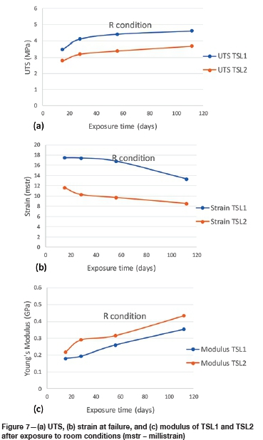
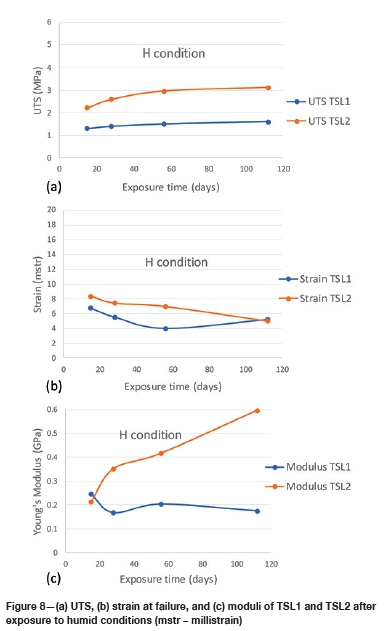
In these figures, the inverse proportionality of the elongation (strain at failure) with exposure/curing time is also observed. However, since the main aim of the research was to assess TSL behaviour in underground mine-like conditions, it is important to consider the sensitivities in H and HT conditions. The results of this evaluation are presented in Figures 8 and 9.
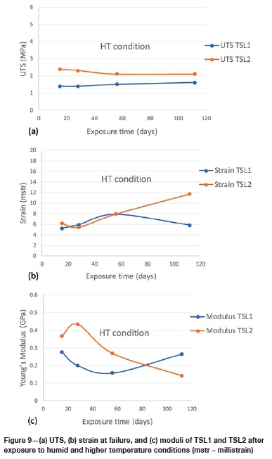
The results presented in Figures 8 and 9 show that only the water-based TSL2 demonstrates a simultaneous strength and modulus proportionality with exposure time in saturated conditions. Based on the tests on the two materials, TSL strength, modulus, and elongation behaviour are generally adversely affected in H and HT conditions, leading to irregular and inconclusive behaviour trends. These negative impacts are also demonstrated by the direct comparison of the strength, modulus, and elongation behaviour of a TSL under various environmental conditions. TSL1 strength and elongation are always lower in H and HT conditions compared with room conditions. At longer exposures in these environmental conditions, the stiffness of TSL1 also decreases. This shows that the risk of failure of TSL1 is higher in H and HT conditions than in room conditions.
A direct comparison of the strengths of TSL2 in room, H, and HT conditions shows that saturated conditions reduce the strengths observed in room conditions. In addition, the strength of this liner is further reduced with exposure to HT conditions. The strain at failure decreases in saturated conditions, but is increased when extensively exposed to HT conditions. The stiffness increases on longer exposure to humid conditions, but decreases significantly when exposed for longer periods in HT conditions. Therefore, liner TSL2 may not be appropriate for use under HT conditions, but would be preferred to TSL1 for H conditions. TSL3 requires more thorough investigation, since its strength was shown to decrease with time, even in room conditions.
Discussion
Tensile strength results on three TSLs under three different environmental conditions have been presented. It is believed that this is the first publication to report on laboratory testing of TSL properties in conditions representative of underground environmental conditions, noting that 100% saturation represents an extreme condition. The specimens that were used for H and HT tests were prepared and allowed to set in room conditions for three days before being exposed to H and HT conditions. Although this practice does not represent what actually occurs in the field (TSLs are exposed immediately to the mine environment), it was adopted to allow for initial setting of the specimens before handling them, to avoid affecting their integrity during the handling process. It is believed that the UTS values of specimens subjected to H and HT conditions just after preparation may well be lower than the indicated results, and this will need to be checked by further testing. The preparation and testing of specimens for the type of testing described in this paper is very time-consuming, and the evaluations reported from this research required considerable time and effort, hence the limited number of TSLs considered. This perhaps is a reason why no reports of similar testing information could be found in the literature. In spite of the limited number of TSLs tested, however, the results obtained from this research are considered to be very significant, since they serve as a warning to TSL users that performance determined from laboratory tests under 'standard' room conditions is most unlikely to be representative of performance in deep-level operations, where conditions will be hot and humid, and therefore the 'real' performance data must be taken into account for support design.
The test results showed, as expected for cementitious products, that TSL1 and TSL2 strengthened with curing time under room conditions. In contrast, TSL3's UTS decreased with curing time under room conditions. It was observed that the UTS increases of TSL1 and TSL2 continued even beyond the conventional period of 28 days, although at different incremental rates. TSL3 showed a decrease in strength with curing time. In all cases, care was taken that specimens from the same sample were used for different curing times.
When TSLs are exposed to saturated conditions, their tensile strengths reduce compared with their performance under room conditions. Though TSL2, a water-based liner, shows the best incremental H curve, its overall H strength remains lower than the room UTS. Therefore, omission of the humidity factor in the strength assessment of multi-component liners may lead to an overestimation of their strength, and their use could be significantly unconservative. However, the ultimate strength should not be the decisive design parameter. In practice, liners will also be subjected to creep loading, and this must be taken into account in their design. The creep properties of the TSLs are not dealt with in this paper.
In HT conditions, all the TSLs underperformed, although TSL2 performed satisfactorily under H conditions. No significant differences were observed between H and HT behaviour for TSL1 and TSL3, with the humidity factor affecting behaviour to a greater extent than the temperature alone. TSL2, however, is more sensitive to HT conditions, and high temperature significantly affects its integrity. These conclusions are considered to be preliminary, and additional studies are recommended to confirm the sensitivity of these liners to a variety of high-temperature conditions.
Generally, the UTS of TSLs increases over time under room conditions. However, even when applied in room-like conditions, if the self-supporting capability of the rock mass is limited, the liners will be under stress from the deforming rock mass immediately after application, and similarly in H and HT conditions. Therefore, under such deforming conditions, independently of the environmental conditions, TSLs should be combined with retaining supports such as rockbolts to counter the early disturbing forces while curing takes place.
In addition to the tests described in this paper, creep testing was carried out on the same TSLs, as well as tests of tensile performance when bonded to a substrate. The results of these tests will be described in further publications.
Conclusions and recommendations
The results obtained from laboratory testing of two types of TSL confirmed their strengthening with curing time in room conditions, even beyond the 'conventional' 28 days. A third type, TSL3, was an exception, and its strength decreased with curing time.
Humid conditions impacted adversely on the tensile strengths of all three TSLs tested. It was observed that the tensile strengths of these liners remained lower than their strengths measured in room conditions, with the decrease ranging between a third and two-thirds of the room strengths. This might be one of the reasons behind the underperformance of TSLs that has been observed in the mining environment. However, of the three TSLs, the water-based TSL2, although weaker in saturated conditions than in room conditions, showed better strength and modulus increases, proportional to longer H exposures. Its elongation remained inversely proportional to H exposure time, unlike the inconclusive modulus and elongation trends observed for TSL1 and TSL3.
In HT conditions, the tensile strength of all three TSLs reduced with exposure time. The stiffness of the water-based liner TSL2 reduced, while its elongation tended to increase; unlike TSL1, which showed inconclusive stiffness and elongation trends. These findings show that the integrity of TSLs is strongly compromised by HT conditions.
The trends in TSL performance when exposed to various environmental conditions show that the combination of humidity and temperature has a greater detrimental impact on TSL strengths. For instance, TSL1 and TSL2 show a logarithmic trend of strength increase over time in room conditions, but a decline or lower incremental rate of performance when exposed to humidity and high-temperature conditions, particularly after extensive exposure periods.
The elongations of TSL1 and TSL2 are inversely proportional to their strengthening and moduli in room conditions. The water-based TSL2 also shows this behaviour in the H condition.
It is to be noted that the conclusions reported are based on tests carried out on only three TSLs and must therefore be regarded as preliminary. Similar studies on more TSLs, especially ductile TSLs, could lead to alternative conclusions. However, the results presented in this paper are considered to be important, since they serve as a warning to TSL users that performance determined from laboratory tests under room conditions is most unlikely to be representative of performance in deep-level operations, where conditions will be hot and humid. In summary, the use of TSLs in H and HT conditions may be unconservative and requires further thorough investigation. For support design, TSL performance under actual expected mining environmental conditions must be considered to avoid underestimation of risks related to TSL utilization.
References
ASTM D-638, 2010. Standard test methods for tensile properties of plastics. ASTM International. West Conshohocken, PA. [ Links ]
Findley, W.N. and Davis, F.A. 2013. Creep and Relaxation of Nonlinear Viscoelastic Materials. Elsevier. [ Links ]
Güner, D. and Oztürk, H. 2018. Creep behaviour investigation of a thin spray-on liner. International Journal of Rock Mechanics and Mining Sciences, vol. 108. pp. 58-66. [ Links ]
Hoek, E., Kaiser, P.K., and Bawden, W.F. 2000. Support of Underground Excavations in Hard Rock. CRC Press, Boca Raton, FL. [ Links ]
Hudson, J.A. and Harrison, J.P. 2000. Engineering Rock Mechanics: An Introduction to the Principles. Elsevier, Amsterdam. [ Links ]
Kanda, M. and Stacey, T. 2019. Review of the practical effectiveness of thin spray-on liners based on information from suppliers and observations from the mining industry. Proceedings of the First International Conference on Mining Geomechanical Risk. Australian Centre for Geomechanics, Perth. pp. 443-458. [ Links ]
Kuijpers, J., Sellers, E., Toper, a., Rangasamy, T., Ward, T., Van Rensburg, a., Yilmaz, H., and Stacey, R. 2004. Required technical specifications and standard testing methodology for thin sprayed linings. SIMRAC Project SIM 20206. Safety in Mines Research Advisory Committee, Johannesburg. [ Links ]
Minerals Council South Africa. 2018. Annual Report. https://www.mineralscouncil.org.za/industry-news/publications/annual-reports [accessed 6 June 2019]. [ Links ]
Mpunzi, P., Masethe, R., Rizwan, M., and Stacey, T. 2015. Enhancement of the tensile strengths of rock and shotcrete by thin spray-on liners. Tunnel and Underground Space Technology, vol. 49. pp. 369-375. [ Links ]
Osswald, T.A. 2015. Understanding Polymer Processing: Processes and Governing Equations. Carl Hanser, Munich. [ Links ]
Potvin, Y., Stacey, T.R., and Hadjigeorgiou, J. 2004. Surface support in mining. Australian Centre for Geomechanics, Perth. [ Links ]
Stacey, T.R. and Yu, X. 2004. Investigations into mechanisms of rock support provided by sprayed liners. Ground Support in Mining and Underground Construction. Proceedings of the 5th International Symposium on Ground Support, Perth, Australia,. Villaescusa, E. and Potvin, Y. (eds). Balkema, Rotterdam. pp. 563-569. [ Links ]
Szwedzicki, T. 2003. Rock mass behaviour prior to failure. International Journal of Rock Mechanics and Mining Sciences, vol. 40. pp. 573-584. [ Links ]
Tannant, D. 2001. Thin spray-on liners for underground rock support-testing and design issues. Proceedings of the International Seminar and Field Trials on Surface Support Liners: Membrane, Shotcrete and Mesh. Australian Centre for Geomechanics, Perth. pp. 1-18. [ Links ]
Yilmaz, H. 2010. Tensile strength testing of thin spray-on liner products (TSLs) and shotcrete. Journal of the Southern African Institute of Mining and Metallurgy, vol. 110. pp. 559-569. [ Links ]
 Correspondence:
T.R. Stacey
Thomas.Stacey@wits.ac.za
Received: 4 Oct. 2019
Revised: 3 Feb. 2020
Accepted: 17 Feb. 2020
Published: April 2020
Appendix A
Representative stress-strain curves
In these curves, the small offsets that can be seen at the origin are due to the preloading of the specimens.

