


Services on Demand
Article
 English (pdf)
 Article in xml format
 Article references
Indicators

Related links
-
 Cited by Google
 -
 Similars in Google
Share

 Permalink
Journal of the Southern African Institute of Mining and Metallurgy
On-line version ISSN 2411-9717
Print version ISSN 2225-6253
J. S. Afr. Inst. Min. Metall. vol.120 n.3 Johannesburg Mar. 2020
http://dx.doi.org/10.17159/2411-9717/792/2020
PAPERS OF GENERAL INTEREST
Measuring and modelling entrainment in rougher and cleaner batch flotation
N.V. Ramlall
South Africa
SYNOPSIS
A study was carried out to measure the recovery by entrainment from batch rougher and cleaner flotation tests. A non-floatable tracer component (ferrosilicon, FeSi) was added to milled Merensky ore in the flotation test work and used to measure the recovery by entrainment. Conventional entrainment models such as the linear model and the exponential probability model gave poor model fits. A new entrainment model is therefore proposed in this study. A three-parameter Weibull probability model was fitted simultaneously to the rougher and cleaner entrainment recovery data. The model gave a good fit and returned parameters that are a logical description of the recovery by entrainment in both rougher and cleaner batch flotation.
Keywords: entrainment measurement, entrainment modelling, batch flotation.
Introduction
In mineral flotation, the nonselective recovery of non-floatable minerals (typically termed gangue) is due to a process of entrainment. Entrainment is an undesirable process that reduces the flotation concentrate grade. Operational changes (physical and/or chemical) are required to reduce the recovery of gangue minerals by entrainment so that an acceptable concentrate grade can be obtained. Many authors have investigated entrainment at the bench scale, and these studies can be broadly categorized as measurement or modelling studies.
Measurement studies have been carried out by Trahar (1981), Warren (1985), and Ross (1989). Trahar (1981) proposed carrying out two batch flotation tests, one with frother only and another with frother plus collector. The mineral recovery data was plotted against water recovery. Recovery by entrainment was assumed to occur only in the frother test, and recovery by true flotation and entrainment in the frother plus collector test. The difference in mineral recovery between the two tests, at similar water recoveries, was assumed to be recovery by true flotation. This approach assumes that the recovery by entrainment is the same for both tests for similar water recoveries. However, conditions in the pulp and froth phase are different in each test. These differences influence the water content in the froth and ultimately the recovery by entrainment. Water is the medium responsible for transporting particles that are susceptible to entrainment. A brittle froth (typical of low solids concentration) has a loose froth structure with low bubble coalescence, and recovery by entrainment from this froth structure is greater than for a non-brittle froth. When a collector is added to the pulp, it causes hydrophobic minerals (in addition to naturally floatable minerals) to move towards the froth. The froth, having a higher solids content (lower water content), carries less entrained particles. According to the bubble swarm theory proposed by Smith and Warren (1989), the rising column of mineralized bubbles in the froth, which also contains solids suspended in the water interstitial to the mineralized bubbles, squeezes out the water and suspended solids. This froth structure promotes rejection of entrained particles. As a result, recovery by entrainment will be different in both tests because of the different froth structures. The method of Trahar was also restricted to batch rougher flotation, so there is no evidence that entrainment measurements made in rougher flotation are valid in re-flotation.
Warren (1985) carried out batch rougher flotation tests at different froth depths and removal rates. The final recoveries from all tests were plotted against the associated water recoveries. A linear model was fitted to the data; the intercept and slope were related to the recovery by true flotation and the degree of entrainment respectively. In this approach, several rougher flotation tests had to be carried out. This is time-consuming and the froth structure is different for each test. Hence, the recovery by entrainment will be different in each test and there will be some uncertainty about the parameters estimated. Also, it is not known if the parameters determined from rougher flotation apply to re-flotation.
Ross (1989) carried out a single batch rougher flotation test for measuring recovery by entrainment. Two transfer functions were defined, one for entrained solids and another for total solids to the flotation concentrate. It was assumed that the recovery towards the end of the rougher flotation test was mainly due to entrainment, therefore the transfer function for total solids towards the end of flotation was used to estimate the recovery by entrainment. The froth structure changes during batch flotation because of the varying solids concentration in the froth. Early in the test the froth solids concentration is high (i.e. low water content in the froth), and as the test progresses, the froth solids concentration decreases because of less floatable minerals being present. The transition of the froth structure, from a low water content (at the beginning) to high water content (towards the end), means that entrainment measurements made at the end of flotation may not necessarily apply to the batch flotation test over its entire duration. Wang et al., (2015) cautioned on the use of this approach for re-flotation, since the higher concentration of floatable minerals in the cleaner stage means that the degree of entrainment measured towards the end of flotation may exceed unity. This is impossible if non-floatable gangue recovery is by entrainment only. This also implies that data-points at the end of flotation do not constitute a reliable measure for estimating entrainment.
Konopacka and Drzymala (2010) reviewed the graphical representation of entrainment and the models used to describe these representations. Figure 1 shows the five types of representations found by the authors. The representations vary from linear (Types 1, 2, and 5) to nonlinear (Types 3 and 4). According to the authors, the shapes of the entrainment curves are the result of the way the flotation test is carried out, the type of flotation machine used, kinetics of the process, froth collecting time, the concentration of frothers, collectors and modifiers, the amount of air, density of the pulp, and supplied water. For the representations, the entrainment recovery is defined as the cumulative mass recovery of the mineral to the concentrate by entrainment divided by initial mineral mass content in the pulp. This is then expressed as a percentage. Water recovery may be defined in several ways, such as percentage water recovery (cumulative recovery to concentrate relative to pulp initial water content), mass of water recovery (cumulative mass of water recovered to concentrate), volume of water recovered (cumulative volume of water recovered to concentrate), and water flow rate (cumulative mass flow rate of water recovered to concentrate,expressed in units of g-min-1 or similar). A brief discussion on each curve type, based on the paper of Konopacka and Drzymala (2010), is given below. It is recommended that the original work of these authors be read for more information.
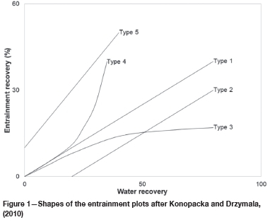
The Type 1 curve is a linear entrainment curve for which mineral entrainment is proportional to water recovery. Equation [1] is typically used to model this type of entrainment curve. Rentis the cumulative recovery by entrainment, ENT is the degree of entrainment (which varies from 0 to 1), and Rwateris the cumulative water recovery (typically expressed in per cent). There is one concern with the use of this model in batch flotation. Consider the situation of an ENT value close to unity, e.g. 0.85 reported by Warren (1985) for fine gangue. For batch flotation, the recovery of water can exceed 100% if water is continually added to maintain the pulp volume. Consequently, recovery by entrainment can exceed 100% mathematically, although this is impossible in practice. For ENT = 0.85, Rentexceeds 100% when Rwateris greater than 118%.

The Type 2 entrainment curve is a linear curve that is shifted down the abscissa of the plot. This may be attributed to the feed containing coarse particles and the froth height being low. A linear model was used to model this curve, but a correction factor (Rwater,0) was added to water recovery to account for the downward shift. All other parameters have the same definitions as those given for Equation [1].

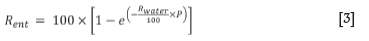
Type 3 is a nonlinear entrainment curve. The recovery by entrainment increases gradually and then approaches a plateau. Kirjavainen (1989) proposed Equation [3] to describe this curve. Here P is a dimensionless entrainment separation coefficient that varies between 0 and 1. All other parameters have the same definitions as for Equation [1].
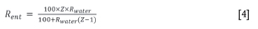
Type 4 is an entrainment curve that is parabolic. According to Konopacka and Drzymala (2010), this curve has been observed in studies carried out by Lynch et al. (1974), Engelbrecht and Woodburn (1975), and Bisshop and White (1976). Laplante (1980) presented Equation [4] for this type of curve. Here Z is called the classification entrainment coefficient and varies between 0 and 1. All other parameters have the same definitions as for Equation [1].
Type 5 is a linear entrainment curve that is shifted upwards along the ordinate of the plot. The upward shift is due to the occurrence of hydrophobic minerals (fully liberated or composite particles) that attach to ascending bubbles; these minerals are then recovered in the flotation concentrate. To account for this, Warren (1985) proposed the model given by Equation [5]. Here Rflotationis the recovery by flotation; all other parameters have the same definitions as for Equation 1.

In summary, some drawbacks were observed regarding entrainment measurement and modelling studies:
> All studies were carried out using batch rougher tests, and there is no evidence that the entrainment measurements made in rougher flotation apply to re-flotation.
> The froth structure changes over the duration of the batch flotation test. Therefore, entrainment measurements made with particular data-points (such as data at the end of flotation) may not represent entrainment over the entire duration of flotation.
> There are a veritable plethora of entrainment models, each modelling entrainment for a particular flotation test methodology. This implies that no single model exists for representing the different types of entrainment curves that may be observed. Furthermore, these models were applied to rougher flotation and were not extended to re-flotation tests. Therefore it is not known if rougher fitted parameters apply to re-flotation.
In this study, a tracer component (FeSi) was used to investigate the recovery by entrainment. FeSi was added to milled Merensky ore conditioned with typical flotation reagents. The entrainment of FeSi from a naturally occurring ore and the observation of its recovery in both rougher and cleaner flotation leads to a more realistic study of entrainment. The primary objective of this study is to investigate and model entrainment changes between rougher and cleaner flotation.
Methods
Samples
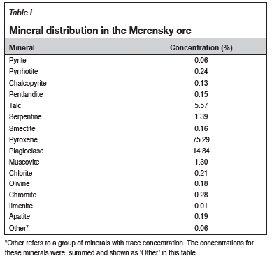
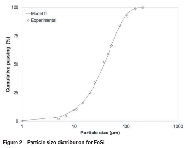
Merensky ore was used in all flotation test work. The ore was crushed to -1.7 mm and split with the aid of rotary sample dividers (RSDs) into 2 kg aliquots for the test work. The sample had a Pt, Pd, plus Au (2PGE+Au) feed grade of 2.93 g-t-1. Table I shows the mineral types and their distribution in the sample. The minerals are mainly paramagnetic (weakly magnetic) and diamagnetic (nonmagnetic). FeSi was used as a tracer component for measuring entrainment because of its ferromagnetic (strongly magnetic) properties. It can be recovered from the flotation products (concentrates and tails) using magnetic methods without recovering other minerals. Figure 2 shows the size distribution of the FeSi used in this study. A Rosin-Rammler particle size distribution model was fitted to the experimental data, which was obtained from laser sizing using a Fritsch Analysette 22. The specific density (SG) of FeSi was measured with a pycnometer and found to be 5.01.
Experimental
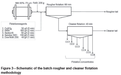
Figure 3 shows a schematic of the batch rougher and cleaner flotation test set-up. For the batch rougher flotation test, the Merensky ore was milled to 65% passing 75 μm using a rod mill. The milled ore was transferred into a 5 L flotation cell and tap water was added to the flotation pulp to give a solids concentration of 35% in the pulp. The pulp was conditioned with flotation reagents typically used in Merensky ore flotation. A Denver D-12 flotation machine and mechanism were used with the impeller speed set to 1500 r/min. After conditioning, FeSi was added into the flotation pulp, which was agitated for a further 30 seconds. Air was introduced into the flotation cell at a rate of 8.3 L-min-1. The air flow rate was set to this value for better control of the froth since higher flow rates created a voluminous froth that was difficult to scrape at consistent intervals. This may be due to the ore containing a large amount of floatable material. The froth was allowed to build up naturally (allowing mineral separation to occur in the froth) and removed by hand-scraping every 15 seconds. The bottom edges of the scrapers were kept at a constant level of 5 mm above the froth/pulp interface. This is typical of most batch flotation test procedures, which use hand-scraping of the froth. Eight flotation concentrates were collected, ending at the cumulative flotation times of 1, 3, 7, 20, 30, 40, 50, and 60 minutes. Tap water was used to maintain the pulp level throughout the test. The flotation concentrates and the tails were weighed before filtration and again after drying. This made it possible to calculate the recovery of water.
For the cleaner tests, rougher flotation was first carried out as discussed above. The rougher concentrates collected over 60 minutes were combined and filtered. The undried rougher concentrate filter cake was transferred into a 2.5 L flotation cell and re-pulped to a suitable pulp height using the filtrate from rougher concentrate filtration. In re-flotation, the impeller speed was set to 1200 r/min, and the pulp was agitated for 2 minutes before the air was introduced at a rate of 4 L-min-1. The froth was allowed to develop, and hand-scraping was used to remove the froth every 20 seconds. Six concentrates were collected, ending at cumulative flotation times of 1, 3, 7, 20, 30, and 40 minutes. The filtrate from rougher concentrate and tails filtration was used to maintain the pulp level. The flotation concentrates and tails were weighed before filtration and again after drying so the water recovery could be calculated. No reagents were added to cleaner flotation so as not to introduce additional variables into the study.
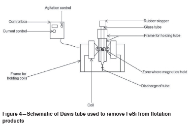
FeSi was recovered from the rougher and cleaner flotation concentrates and tails using a Davis tube (Figure 4). This device is typically used to determine the amount of magnetic material in a sample. The solids were placed into the glass tube that contained water, and an electric current was introduced into the device. The current is related to a certain magnetic flux density. In this study it was 1000 gauss, which is sufficient for recovering ferromagnetic material only and not diamagnetic and paramagnetic material. The ferromagnetic material was held between the poles in the magnetic zone. Water was introduced into the tube at a rate of 1.5 L-min-1 using a peristaltic pump. The continuous flow of water into the tube, together with agitation of the tube, aids in the separation of paramagnetic and diamagnetic material (which exits at the discharge end of the tube) from the ferromagnetic FeSi material, which is held in the magnetized zone. A mass balance of material recovered to tube discharge and that held in the magnetized zone gave the distribution of FeSi in each flotation concentrate and tail. It should be noted that the mass introduced into the Davis tube should be small. Therefore, smaller masses had to be split out from the dried flotation rougher and cleaner tails before testing. For the rougher and cleaner tails, three 30 g sub-samples were split off using an RSD. Each was tested in the Davis tube and the average result used to determine the FeSi content in each flotation tail. An analytical mass balance was used to measure the mass of FeSi obtained from the Davis tube test.
Results and discussion
Verification of FeSi as a tracer
Before the flotation test work, a sub-sample of milled (65% -75 μm) Merensky ore was passed through the Davis tube. No material was held in the magnetized zone at a magnetic flux density of 1000 gauss. This confirmed that the Merensky ore contained no ferromagnetic minerals. A sample of FeSi was also passed through the Davis tube. All the material was held in the magnetized zone at a magnetic flux density of 1000 gauss. This confirmed that FeSi can be used as a tracer since its distribution across the flotation concentrates and tails can be determined using a Davis tube.
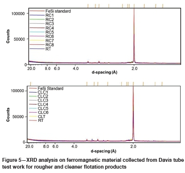
The ferromagnetic material obtained from the Davis tube for each flotation product was subjected to X-ray diffraction (XRD) analysis. XRD analysis is a nondestructive test since the mass used can be recovered and reused after the test. This test was used to identify whether the magnetic material recovered by the Davis tube was FeSi. A FeSi sample was also introduced into this analysis as a standard for comparing the XRD patterns obtained for other samples. Figure 5 shows the results of the XRD analysis, confirming that the ferromagnetic material collected from each flotation product was FeSi and not another mineral.
The last step in verification was a mass balance of FeSi across the flotation products. After the XRD analysis, the samples were subjected to laser sizing using a Fritsch Analysette 22.
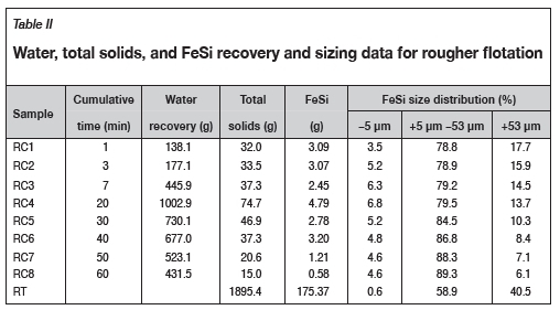
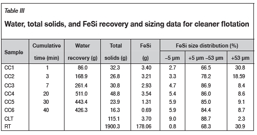
Table II and Table III show the mass distribution of water, total solids, and FeSi across the batch rougher and cleaner flotation tests respectively. Total solids include the mass of magnetic (FeSi) and nonmagnetic minerals. For the rougher test, the FeSi recovered from the three 30 g rougher tail sub-samples was 2.789, 2.808, and 2.730 g. For the rougher-cleaner test, the FeSi recovered from the three 30 g rougher tail sub-samples was 2.791, 2.781, and 2.861 g, and for the three 30 g cleaner tail sub-samples it was 0.969, 0.946, and 0.975 g. These values are comparable and show minimal variation across the triplicate testing. The average of the three was used to determine (by proportion) the FeSi content in the rougher and cleaner tails. A mass balance for FeSi shows that for 200 g introduced into each flotation test, 196.54 g of FeSi was recovered from the rougher test and and 196.84 g from the rougher-cleaner test. The good agreement between the mass introduced and mass recovered supports the application of FeSi as a tracer.
Modelling recovery by entrainment
A mass reconciliation was carried out on the FeSi distribution across the rougher and cleaner flotation test work. It is necessary to use balanced data for linking entrainment measurements between rougher and cleaner flotation. Figure 6 shows a parity chart of the reconciled FeSi distribution and the experimental distribution as set out in Table II and Table III.
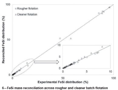
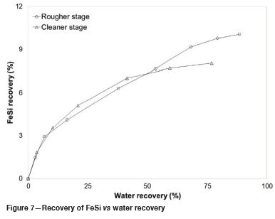
Figure 7 shows the total recovery of FeSi versus water recovery. FeSi recovery was determined with respect to the total amount added to the rougher feed. The recovery of water from rougher and cleaner flotation was determined with respect to the initial amount of water added to each stage. FeSi recovery does not follow the typical linear relationship expected between entrainment and water recovery. The relationship is nonlinear and resembles the Type 3 relationship reported by Konopacka and Drzymala (2010). Also, entrainment recovery appears to approach a plateau for each stage of flotation. This trend is not unusual and has been reported by other authors. EkmekÇi et al. (2003) investigated the effects of frother type and froth height on the entrainment behaviour of chromite from UG2 ore. They obtained a similar curve for the +45 urn chromite size fraction. The chromite recoveries at 30% and 50% water recovery (the last two data-points on their curve) were about 0.12% and 0.14% respectively, indicating that recovery approaches a plateau.
Kirjavainen (1989) investigated the entrainment of 1 μm chromite and silica in batch flotation. The entrainment recovery of both minerals also approached a plateau towards the end of flotation.
The approach of recovery by entrainment to a plateau suggests that the flotation operating conditions limit the recovery. For both rougher and cleaner flotation, the duration of flotation was much longer than that typically used in Merensky ore flotation. Flotation was deliberately prolonged to examine the behaviour of mineral entrainment at extended batch flotation times. For the rougher stage, even at a water recovery of almost 89%, the entrainment recovery does not approach an absolute maximum of 100%. Instead, the recovery approaches a plateau of about 10%. This implies that entrainment recovery is constrained with respect to prevailing pulp conditions (i.e. air flow rate and impeller speed) as well as froth conditions (i.e. depth and scraping rate). Evidence for this reasoning can be found in a study by Zheng, Johnson, and Franzidis (2006), in which the entrainment of silica was measured for varying froth heights and air flow rates. The authors found that the degree of entrainment increased for increasing air flow rate and decreasing froth height. This observation suggests that entrainment recovery is constrained by prevailing flotation operating conditions (either in the pulp or the froth), therefore a particular maximum recovery by entrainment can be expected under these conditions.
The initial water content in the pulp is different for each stage, therefore simultaneous modelling of rougher and cleaner data is not possible. A new entrainment model is proposed for modelling the recovery by entrainment across batch rougher and cleaner flotation. The water flow rate was used instead of water recovery. The water flow rate is defined as the mass of water recovered per unit time for each flotation concentrate. This parameter is independent of the initial amount of water added to a batch flotation pulp. Therefore, rougher and cleaner entrainment measurements can be linked using the water flow rate. After assessing the profile of cumulative FeSi recovery with cumulative water flow rate for each flotation stage, a three-parameter Weibull model was suggested for modelling this curve. This gave a probabilistic model, defined as:
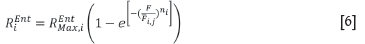
where
RiEnt is recovery by entrainment for particles in size class i
REntMax,iis a model-fitted parameter which describes the maximum amount that can be recovered by entrainment for particles in size class i
F is the experimental water flow rate (g-min1)
Fij is a model-fitted parameter that describes the scale of the model. It is the water flow rate (g-min-1) that results in 63.2% of maximum entrainment recovery being attained for particles in size class i in flotation stage j
niis a dimensionless model-fitted parameter that influences the shape of the Weibull probability distribution for particles in size class i
In Equation [6], the term  represents a probability, so this quantity varies between 0 and 1. The probability (Pr) is influenced by the water flow rate, which changes over the duration of the flotation test because of depleting floatable mineral content and frother concentration in the flotation pulp. Therefore, Equation [6] can be expressed as follows:

The model was fitted simultaneously to the rougher and cleaner flotation data. There are 14 data-points for each size class. For each size class under examination, only four parameters had to be determined during model fitting, these were REntMax,i , Fi,rougher,Fi,cleaner, and n. The parameter REntMax,idescribes the maximum amount of material that can be recovered by entrainment from the rougher stage. The maximum amount that can be entrained in the cleaner stage can be determined as bEntMax,i . Pr, where Pr is the probability associated with the_ final concentrate collected from rougher flotation. Fi,rougherand Fi,cleaner describe the scale of the model, that is, the water flow rate that results in 63.2% of the maximum entrainment recovery being achieved for a stage. The value of 63.2% is obtained when Fi,rougher and Fi,cleanerare equal to F for each flotation stage. At this value,  is equal to 63.2%. The cleaner stage is more selective than the rougher stage due to the meticulous removal of the froth, that is, longer froth retention time (20 seconds versus 15 seconds for rougher flotation), and dilute pulp conditions. Hence, it was logical to define different model scale parameters for rougher and cleaner flotation. The parameter n(controls the shape of the probability model. As n decreases, the shape of the curve produced by the model becomes more like the Type 3 curve reported by Konopacka and Drzymala (2010). For increasing n , the model becomes more vertical and linear about the scale parameter and appear like the Type 1 curve.
The probabilistic model was fitted to the recovery by entrainment data for particle size classes -5 urn, +5 μm -53 μm, and +53 μm. Figures 9-11 show the model fit to these size classes. Also, the total FeSi recovery by entrainment was determined from the model-fitted parameters for each size class and the proportion of the particle size class in the flotation rougher feed. This fit is shown in Figure 8. The model gave a good fit to the experimental data for different particle size classes in the different flotation stages. The adjusted coefficient of determination (a statistic used to assess model fit to experimental data) was determined for a total of 56 data-points (14 per size class and 14 for total FeSi) and 12 model parameters (i.e. four model parameters per size class). A value of 0.9935 was obtained; this indicates a good model fit.
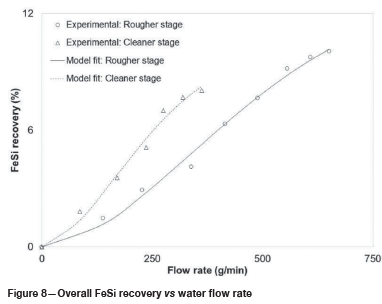
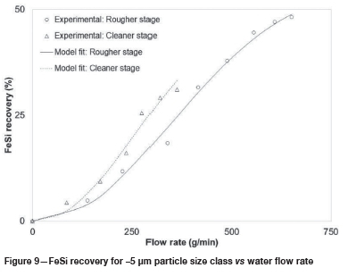
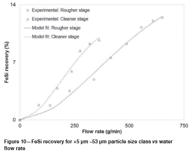
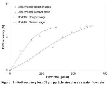
Table IV shows the parameters obtained from the fitting of the model to the experimental data. The maximum amount that can be recovered by entrainment (REntMax,i ) decreases with increasing particle size. This parameter can be interpreted in a similar way as the ENT parameter for the linear entrainment model shown in Equation [1]. In that model, ENT decreases with increasing particle size. Similarly REntMax,idecreases with increasing particle size. This is logical since larger particles tend to sediment in the flotation pulp and have low entrainment recovery. On the other hand, smaller particles tend to follow the fluid streamlines into the froth, due to their lower particle inertia, and have a higher recovery by entrainment. Zheng, Johnson, and Franzidis (2006) carried out entrainment studies using a 3 m3 Outokumpu tank cell. In their study, the air flow rate and froth height were varied and the degree of entrainment for silica was measured. For an air flow rate of 1.10 m3-min-1 and froth height of 9.6 cm, the ENT values for particles with average sizes similar to this study were extracted from the graphical plots: ENT=0.56 (7 um), 0.18 (25 μm), and 0.11 (88 μm). Therefore, the REntMax,iparameter from this study is analogous to the ENT parameter and varies logically with particle size.
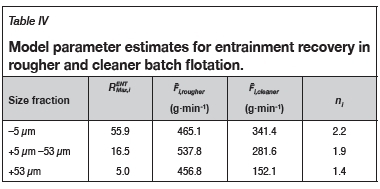
The scale parameter (Fij)for rougher flotation does not show a particular trend with particle size. This may be due to the nonselective operating conditions in rougher flotation. In rougher flotation, the set-up is designed for maximum mineral recovery. However, in cleaner flotation the longer froth scrapes, lower air flow rate, and dilute pulp conditions create a more selective environment. This may explain the decrease in scale parameter with increasing particle size in cleaner flotation. The lower model estimates for the scale parameter in cleaner flotation than the rougher flotation result in a horizontal shift in the probability model to the left. This indicates a lower probability of entrainment due to a more selective environment in the cleaner flotation stage.
The shape parameter (ni) decreases with increasing particle size. This, together with decreasing estimates of the scale parameter, indicates that the probability of entrainment decreases with increasing particle size.
The shape of the entrainment curves (Figures 9-11) is unusual in comparison to curves reported in the literature. The use of water flow rate may be partially responsible. However, a closer examination of the curves shows features that may have a physical meaning. Consider the entrainment of fines (Figure 9). The curve shows three distinct parts; a slow recovery initially followed by a faster recovery and then a gradual slowing down of recovery. At the beginning of flotation, the pulp contains more floatable material and a higher frother concentration. This results in more material (in the form of mineralized bubbles) ascending towards the froth. Water interstitial to the mineralized bubbles contains suspended nonfloatable particles, which can only be recovered by entrainment. As the mineralized bubbles coalesce, the interstitial water and the suspended particles are squeezed out. The suspended particles then drain back into the pulp phase. As the floatable mineral content and frother concentration depletes, the froth contains fewer mineralized bubbles. Consequently, there is less coalescence of the mineralized bubbles. This results in a brittle froth with a higher water content and hence a higher amount of suspended particles. Therefore, entrainment increases during the intermediate period of batch flotation. Towards the end of batch flotation, there are barely any floatable minerals and the frother concentration is at its lowest. The entrainment recovery approaches a plateau at this stage of flotation. This feature may be related more to the pulp conditions than the froth. The low number of ascending mineralized bubbles may not provide sufficient impetus for the transportation of entrainable particles to the froth. Changes to the pulp operating conditions, such as an increase in impeller speed to enhance particle suspension and air distribution, and an increase in air flow rate to drive more particles upwards, can force more particles to enter the froth, as seen in the study of Zheng, Johnson, and Franzidis (2006). However, the recovery by entrainment should logically approach a plateau if pulp operating conditions do not change.
Influence of density and particle size on entrainment
It could be argued that FeSi has a density atypical of most gangue minerals, and as such may not truly represent the entrainment behaviour of gangue. However, mineral density alone does not influence entrainment; the particle size, in addition to density, determines the mass of the particle and its propensity to be entrained. Evidence from the literature and the author's own view will be presented as justifications for using FeSi as a tracer.
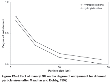
From literature evidence, Wang et al. (2015) presented a review of factors influencing entrainment. The authors cited a study carried out by Maachar and Dobby (1992), who investigated the influence of density on the degree of entrainment. According to this study, the degree of entrainment was measured for two hydrophilic gangue minerals, silica (SG 2.6) and galena (SG 7.5). Figure 12 presents the results of this study. The degree of entrainment increased with decreasing particle size for both minerals. Furthermore, the degree of entrainment was greater for silica than galena for similar particle sizes, but the difference was minimal. At a particle size less than 5 um, the degrees of entrainment for silica and galena were 0.74 and 0.70 respectively. According to Wang et al. (2015), particle density might interact with other factors which contribute to or affect entrainment in a flotation cell.
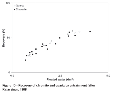
Kirjavainen (1989) carried out batch rougher flotation tests with hydrophilic quartz and chromite at a particle size less than 1 um. Figure 13 shows the result for hydrophilic mineral recovery plotted against the volume of water recovered. The plot does not have the conventional water recovery units in per cent; nevertheless, it does show that both minerals have similar entrainment recovery profiles for similar water recovery, despite their different densities.
In summary, previous studies suggest that the conventional view - that entrainment is greater for minerals of lower density and lower for minerals of a higher density - is not completely correct. Other factors such as particle size must also be considered. Particle size and mineral density determine the mass of a particle, which in turn determines its susceptibility to being entrained. To expand on this, a brief explanation is given on particle motion in relation to a fluid. The purpose of this explanation is to show that mineral mass is the driving factor that influences entrainment.
The recovery of a particle by entrainment can be considered as a two-step process involving particle movement through the pulp phase into the froth, and then from the froth into the collected concentrate. In the pulp, an impeller is used to agitate the solids and provide suspension, as well as to disperse the air into smaller bubbles. Most particles that have a propensity to be entrained move towards the froth by following the streamlines of the ascending bubbles. The ability of these particles to follow the streamlines is related to the inertia of the particle. Wang et al. (2014) investigated solid-liquid separation by particle flow instability. The authors considered that when particles are sufficiently tiny they behave as an infinitesimal fluid element and follow the underlying fluid flow. However, when the particles size increases, the inertia of the particle prevents it from instantaneously matching its movement to that of the fluid. The authors then explained that the size and density of the particle moving in a fluid can be captured by the inertia number (a):
where St and R are the Stokes number and density ratio respectively. These are defined as:
Wang et al. did not define the type of Reynolds number used in their study. For this illustration, the Reynolds number will be defined for the pulp phase of flotation, and with respect to initial operating conditions.
where
a is the radius of the particle (m)
L is the flow length scale (m), taken as impeller diameter by Wang et al. (2014)
Re is the Reynolds number
N is the impeller speed (s-1)
D is the impeller diameter (m)
p is the pulp density (kg-m-3)
μ is the viscosity of the pulp (Pa-s)
ppis the particle density (kg-m3)
pLis the fluid density (kg-m3)
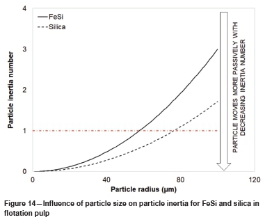
Consider two particles, FeSi and silica, with ppof 5010 and 2650 kg-m-3 respectively. Both particles are present in water with a pLof 1000 kg-m3. Using Equation [10], the density ratios for FeSi and silica were calculated as being 0.18 and 0.32 respectively. The Reynolds number for the flotation pulp was determined for N = 25 s-1(i.e. 1500 r/min), D = 0.05 m, pulp density 1323 kg-m-3, and pulp viscosity 1.30 x10⁻⁴ Pa-s. The pulp density was determined by using the initial mass fraction of each component (water, ore, and FeSi) and their respective densities. Cilek (2009) estimated the pulp viscosity using Equation [12], where μwis the water viscosity (8.90 x10⁴ Pa-s was used in this illustration) and φ is the fraction of the pulp occupied by solids; this was estimated from the initial mass fraction and density of each component in the pulp.

The particle inertia number was estimated for a range of particle sizes using the pulp Reynolds number (which was calculated as 612 502) and the Stokes number. Figure 14 shows the results of this simulation. According to Wang et al. (2014), for σ << 1, the particle moves passively, that is, the particle matches its own velocity to that of the fluid. As a increases, a particle becomes non-passive and its inertia (due to its higher mass) causes it to deviate from the fluid streamlines. So from Figure 14, the inertia numbers exhibited by FeSi and silica are similar up to a particle radius of 25 μm. The inertia number increases more rapidly for FeSi than for silica for a particle radius greater than 25 μm, but the number is still less than unity up to a particle radius of about 100 μm. The key point from this illustration is that fine material (particle diameters less than 50 um for the purpose of this example) exhibits similar inertia numbers, which are much less than unity. This implies that irrespective of particle density, these fine particles will most likely follow the streamlines in the flotation pulp and travel towards the froth. Hence, the classification of particles in the flotation pulp (for entrainment) is strongly related to their inertia and ability to follow the fluid streamlines.
In the froth, a different entrainment classification process takes place. Here the particle settling rate plays a vital role in determining its recovery to the flotation concentrate. According to Kirjavainen (1992) and George, Nguyen, and Jameson (2004), a laminar flow regime may be assumed in the froth phase. Under this regime, the particle settling velocity under hindered conditions may be calculated using Equation [13].
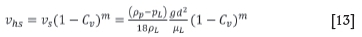
where
vsis the particle settling velocity in an unhindered environment (m-s-1)
g is the gravitational acceleration constant (9.81 m-s2)
d is the particle diameter (m)
ppis the particle density (kg-m3) pLis the fluid density (kg-m3) μL is the fluid viscosity (Pa-s)
vhsis the hindered particle terminal settling velocity (m-s1)
Cvis the the volumetric concentration of solids in the environment (dimensionless)
m is an empirical constant related to the Reynolds number. A value of 4.6 can be assumed for Reynolds numbers less than 0.2.
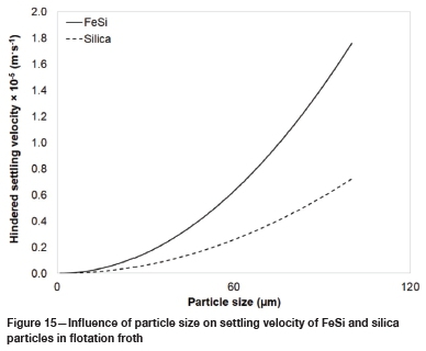
Figure 15 shows the results for the settling velocity of a FeSi and a silica particle at different particle sizes. In this illustration, particle densities for FeSi and silica were set at values given earlier, the fluid viscosity and density were as for water. Cvfor the purpose of this illustration was calculated as 0.07 and was determined for the first concentrate collected from the rougher flotation test. The results from this analysis show that the settling velocities for both particles are similar up to a particle size of 20 μm. In addition to knowing the settling rate of a particle, the upward flow of water should be calculated since this will determine if a particle will settle out of the froth. The water velocity for the first rougher flotation concentrate was roughly estimated using the water collected in that time interval, the density of water, and the surface area at the top of the rougher cell. A value of 6.32 x 10⁻⁵ m-s-1 was calculated. The water velocity is much higher than the settling velocity for the particles at all sizes. This implies that if particles (fines up to coarse) enter the flotation froth, there is a strong chance of these particles being recovered by entrainment.
In summary, the discussion shows that both particle size and density are crucial in determining the susceptibility of a particle to entrainment, since these factors determine the mass of a particle and hence its inertia in the pulp and settling rate in the froth. The lower the inertia of the particle, the greater chance of it following the fluid streamlines into the pulp-froth interface. These particles are pushed into the froth as more mineralized bubbles ascend. Should the particle enter the froth, the settling rate of the particle relative to the fluid velocity determines if the particle will settle out of the froth or be carried into the flotation concentrate.
Conclusions
Recovery by entrainment was measured in batch rougher and cleaner flotation tests using ferrosilicon (FeSi) as a tracer component. The tracer was added to Merensky ore flotation so entrainment could be examined in relation to the flotation of an actual ore and not as a mono-component test involving FeSi only.
The recovery by entrainment from rougher and cleaner flotation, for three different size classes, was not represented adequately by the typical linear and nonlinear entrainment models proposed in the literature. Therefore a three-parameter Weibull probabilistic model was proposed for modelling rougher and cleaner entrainment data simultaneously. The use of water flow rate, rather than water recovery, made it possible to link batch data from rougher and cleaner tests. The model gave a good fit to the experimental data, having an adjusted coefficient of determination of 0.9935. Also, the model-fitted parameters were a logical description of entrainment across rougher and cleaner flotation.
There may be some concern regarding the use of FeSi as a tracer due to its density being higher than that of most gangue minerals. However, evidence from the literature and an example are given to illustrate the influence of particle density and size on entrainment. Both these parameters determine the mass of a particle, which in turn determines the particle inertia in the flotation pulp and settling rate in the froth.
Recovery by entrainment is more dominant for fine particles. For fine particles, the recovery by entrainment appears to be the same (refer to Figure 12) irrespective of particle density. Hence, FeSi can be used as a proxy to measure entrainment, but it is recommended that a size analysis be performed so that the FeSi entrainment parameters determined by particle size (particularly fines, <5 μm) can be applied to entrainment measurements of other non-floatable minerals.
Recommendations
Further work should be carried out to investigate the application of the proposed model to modelling entrainment data from continuous and batch flotation tests. In addition, a more rigorous examination of the influence of particle density should be carried out to supplement the illustrative assessment presented.
Acknowledgements
This study was carried out by the author in his own capacity and does not reflect the views of SGS South Africa on the subject. The author would like to thank SGS for the use of their facilities.
References
Bisshop, J.P. and White, M.E. 1976. Study of particle entrainment in flotation froths. Transactions of the Institution of Miningl and Metallurgy, Section C, vol. 85. pp.C191-194. [ Links ]
Cilek, E.C. 2009. The effect of hydrodynamic conditions on true flotation and entrainment in flotation of a complex sulphide ore. International Journal of Minerals Processing, vol. 90. pp. 35-44. [ Links ]
Ekmekçi, Z., Bradshaw, D.J., Allison, S.A., and Harris, P.J. 2003. Effects of frother type and froth height on the flotation behaviour of chromite in UG2 ore. Minerals Engineering, vol. 16. pp. 941-949. [ Links ]
Engelbrecht, J.A., and Woodburn, E.T. 1975. The effects of froth height aeration rate and gas precipitation on flotation. Journal of the South African Institute of Mining and Metallurgy, vol. 76, no. 3. pp. 125-132. [ Links ]
George, P., Nguyen, A.v., and Jameson, G.J. 2004. Assessment of true flotation and entrainment in the flotation of submicron particles by fine bubbles. Minerals Engineering, vol. 17. pp. 847-853. [ Links ]
Kirjavainen, v.M. 1989. Application of a probability model for the entrainment of hydrophilic particles froth flotation. International Journal of Minerals Processing, vol. 27. pp. 63-74. [ Links ]
Kirjavainen, V.M. 1992. Mathematical model for the entrainment of hydrophilic particles in froth flotation. International Journal of Minerals Processing, vol. 35. pp. 1-11. [ Links ]
Konopacka, Z. and Drzymala, J. 2010. Types of particle recovery-water recovery entrainment plots useful in flotation research. Adsorption, vol. 16. pp. 313-320. [ Links ]
Laplante, A.R. 1980. The effect of air flow rate on the kinetics of flotation. PhD thesis, University of Toronto, Canada. [ Links ]
Lynch, A.J., Johnson, N.W., McKee, D.J., and Thorne, G.C. 1974. The behaviour of minerals in sulphide flotation process with reference to simulation and control. Journal of the South African Institute of Mining and Metallurgy, vol. 74, no. 9. pp. 349-360. [ Links ]
Maachar, A. and Dobby, G.S. 1992. Measurement of feed water recovery and entrainment solids recovery in flotation columns. Canadian Journal of Metallurgy and Materials Science, vol. 31, no. 3. pp. 167-172. [ Links ]
Ross, V.E. 1989. Determination of the contributions by true flotation and entrainment during the flotation process. Proceedings of the International Colloquium: Developments in Froth Flotation. Southern African Institute of Mining and Metallurgy, Johannesburg. https://www.saimm.co.za/Conferences/FrothFlotation/005-Ross.pdf [ Links ]
Smith, G. and Warren, L.J. 1989. Entrainment of particles into flotation froths. Mineral Processing and Extractive Metallurgy Review, vol. 5, no. 1-4. pp. 123-145. [ Links ]
Trahar, W.J. 1981. A rational interpretation of the role of particle size in flotation. International Journal of Minerals Processing, vol. 8. pp. 289-327. [ Links ]
Wang, S., Metcalfe, G., Stewart, R.L., Wu, J., Ohmura, N., Feng, x., and Yang, C. 2014. Solid-liquid separation by particle-flow-instability. Energy & Environmental Science, vol. 7, no. 12. pp. 3982-3988. https://doi.org/10.1039/C4EE02841D [ Links ]
Wang, I., Peng, Y., Runge, K., and Bradshaw, D. 2015. A review of entrainment: Mechanism, contributing factors and modelling in flotation. Minerals Engineering, vol. 70. pp. 77-91 [ Links ]
Warren, L.J. 1985. Determination of the contribution of true flotation and entrainment in batch flotation tests. International Journal of Mineral Processing, vol. 14, no. 1. pp. 33-44. [ Links ]
Zheng, X., Johnson, N.W., and Franzidis, J.-P. 2006. Modelling of entrainment in industrial flotation cells: water recovery and degree of entrainment. Minerals Engineering, vol. 19. pp. 1191-1203. [ Links ]
 Correspondence:
N.V. Ramlall
nv.ramlall@gmail.com
Received: 13 June 2019
Revised: 13 Oct. 2019
Accepted: 13 Dec. 2019
Published: March 2020

