


Services on Demand
Article
 English (pdf)
 Article in xml format
 Article references
Indicators

Related links
-
 Cited by Google
 -
 Similars in Google
Share

 Permalink
Journal of the Southern African Institute of Mining and Metallurgy
On-line version ISSN 2411-9717
Print version ISSN 2225-6253
J. S. Afr. Inst. Min. Metall. vol.120 n.2 Johannesburg Feb. 2020
http://dx.doi.org/10.17159/2411-9717/826/2020
PAPERS OF GENERAL INTEREST
Assessment of errors in the transmission of the orientation and cartographic system from the surface to an underground mine
L. Sanmiquel; M. Bascompta; J.M. Rossell
Polytechnic University of Catalonia, Manresa, Spain
SYNOPSIS
An accurate transmission of the orientation between surface and underground workings, by means of vertical shafts, is a major challenge in the mining industry, especially for deep mines. We assessed the accuracy of this operation in a case study using the two-shaft plumbing and gyroscopic methods in order to compare and analyse the planimetric displacement of the baseline due to different sources of error in each method. The advantages and disadvantages of both methods are discussed. Some disadvantages in each method have been reduced thanks to technological progress, especially in the two-shaft plumbing method. The different sources of error that affect the measurements are analysed in detail with the aim of compensating them and achieving the required precision for an underground infrastructure. Mine ventilation has been identified as one of the most important sources of error in the plumbing method due to intake and return air flow producing a significant displacement of the verticality of the plumbs in the shafts. In this regard, we describe some measures to reduce the influence of ventilation and give details of a compensation method.
Keywords: shaft plumbing, ventilation, plumb oscillation, gravity, Earth rotation.
Introduction
An adequate development of an underground mine or the construction of a tunnel requires the transmission of the cartographic system and orientation from the surface to underground with high accuracy (Stiros, 2009). Maintaining the correct alignment over time is crucial to avoid cost overruns and delays (Yao et al., 2019). Currently, optimization of the measurements is also an important topic in a wide variety of sectors, such as surveying (Stroner, Michal, and Urban, 2017) or civil engineering and construction (Zhang et al., 2018). In the case of deep mining, this task is particularly complex when there is not an existing tunnel connected to the surface, necessitating the use of special techniques (Chrzanowski and Robinson, 1967; Benecke and Kalz, 2006).
However, each mine presents different characteristics: depth, ventilation layout, cross-sections and number of shafts, environmental conditions, presence of water etc. These conditions, together with the required level of accuracy, will affect the method used to transmit the orientation and cartographic system to underground. Hence, there is no standard procedure but different possibilities arise, depending on each case.
Verticality and its control is also important in many sectors and applications, such as buildings and infrastructure. The most widespread system used is based on satellite geo-localization (GPS, GLONASS, Galileo, etc.), which is capable of highly accurate measurements. This system allows different combinations of sensors and surveying equipment to deliver precise and reliable coordinates (van Cranenbroeck, 2010). Unfortunately, it is not possible to use it in mine shafts because the signals do not propagate underground.
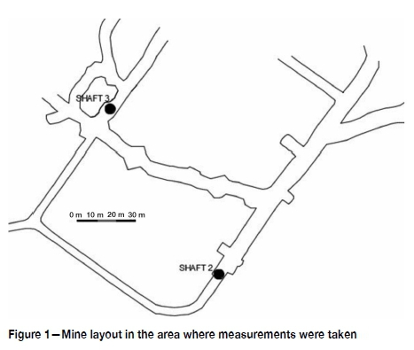
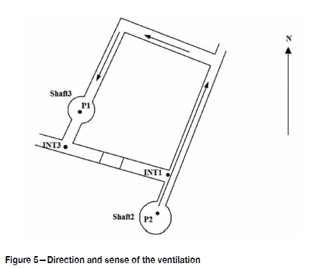
This paper presents a detailed case study with an extensive analysis of the advantages and disadvantages of two commonly used methods - the two-shaft plumbing and gyroscopic methods. The mine assessed is located in Suria, northwest of Barcelona, Spain. It has a depth from 600 to 1000 m below the surface and access is by means of two vertical shafts, each 5 m in diameter and 680 m deep. The first shaft, called Shaft 2, is used for staff access and ventilation intake, while the second, Shaft 3, is used to extract the ore and for ventilation return. The two shafts are around 100 m apart (Figure 1).
The company is planning to connect the underground workings to the surface by a ramp. Several surveys have been done with the idea of transmitting the orientation and the cartographic system from the surface to the beginning of the ramp underground, which is 3500 m away from the shafts. For this reason, it is necessary to ensure that the error in the axis of the tunnel is acceptable, both horizontally and vertically. However, high-accuracy coordinates and orientation is usually one the main problems in tunnel surveying and underground constructions (Urban and Jifikovský, 2015). There are two different options for transmitting topographical information from surface to underground.
➤The two plumbs method is the best option when two shafts are accessible and a gyroscope is not available (Staley, 1964; Estruch and Tapia, 2003). Each plumb is connected to a wire, in the conventional system, running from the top of the shaft to the bottom. This allows reliable results to be obtained in deep shafts. The other option, a laser/ optical system, is not as precise owing to the pressure and temperature differences between the top and the bottom of the shaft, which can create a deviation in the verticality of the laser. However, it is perfectly feasible in the case of shallow shafts, such as at the underground coal mine in Digwadih (Bahuguna, 2003). All activity in the shaft has to be stopped before the operation can be carried out.
➤The gyroscopic survey method is widely used for the transmission of orientations with high accuracy, being able to define absolute directions at any measurement point and eliminate systematic errors (Benecke and Kalz, 2006).
As there are two shafts at the study site and it was important to ensure the accuracy of the measurements, it was decided to use both methods to analyse and validate the results.
Material and methods
Set-up
In the case of the plumb method, one of the main problems is the projection of a point from the top to the bottom of the shaft. It is important to ensure the plumb verticality, with either an optical or a conventional plumb using a cable. The conventional system was used in this study due to some intrinsic characteristics of the mine that are detailed further on. The following preparations were necessary before the measurements:
➤Cover the tops of both shafts with a canvas to reduce the ventilation effect. The remaining ventilation effect is compensated
➤Secure an anti-rotating steel cable 3 mm in diameter at the top of the shaft
➤Connect a 64.4 kg plumb bob with several blades attached to the bottom of the steel cable. The plumb bob is placed inside a 1 m3 tank filed with oil to reduce oscillation
➤Place a 10 χ 10 cm bullseye on the cable to increase the accuracy of the measurements. This is because of the adverse environmental conditions (dust, pollutants, high temperature) in the drift.
This arrangement allows the coordinates to be projected in each of the two shafts. The bullseye enables easier and more accurate measurement with total stations when it is not possible to use a prism to measure distances, having a maximum measurement range of 25 m. Finally, the projected points of both shafts were connected by a polygon. The results obtained can be compared to those obtained by the gyroscope method and used to verify them.
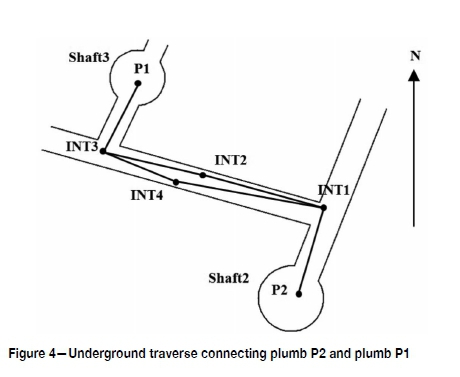
The combination of both methods allowed any alignment of the polygon to be chosen for use with the gyroscope method. In this case, the best alignment was INT3-INT2 (Figure 4) due to logistical constraints. The equipment used is detailed below.
Total station Leica TCRP1201:
Angular accuracy: 1" (3s)
Linear accuracy: 1 mm ±1.5 ppm
Maximum distance measurement without prism: 250 m
Transit level accuracy: 30"
Gyroscope GYROMAX-AK-2M-TM:
Accuracy: 20" (60s)
The technical characteristics of the total station used specify a maximum error of 1 mm ±1.5 ppm, with prism and without prism if a bullseye is used. Before starting with the study, several measurements were taken to verify the precision of the equipment. Two sets of 10 measurements were obtained in two different alignments on two consecutive days, one alignment close to Shaft 2 and the other close to Shaft 3. Moreover, every measurement was taken with a time interval of 30 seconds (Table I).
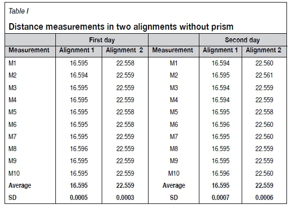
The standard deviation (SD) from the sets of measurements is lower than 1 mm. Therefore, the technical specifications of the equipment have been verified. Zamecnikova et al. (2014) stress the importance of the type of surface from which the laser signal is reflected to avoid errors, being crucial to either the distance or the reflectivity. The use of a bullseye reduces this potential source of error, as can be concluded from the results in Table I.
Two-shaft plumbing method
A plumb was suspended in each shaft and the two were connected by means of an underground traverse. These will be referred to as plumb P1 for Shaft 3 and plumb P2 for Shaft 2.
Two sets of measurements were taken after eight hours without artificial ventilation in Shaft 2 - one set with the entrance of the shaft uncovered and another with the entrance almost completely covered with canvas to minimize the effect of natural air flow on the plumb and quantify its influence to the plumb verticality. The difference in the vertically of the plumbs between the shaft covered and uncovered was 1 cm. Hence, the set of measurements with the shaft covered was taken as correct.
Shaft 3 (the ventilation return shaft) could not be covered since the cover generated turbulence which affected the plumb stability. Hence, the ventilation effect was compensated by several sets of measurements at the bottom of the shaft.
The necessary weight for the plumb bob was calculated from the equation derived by Taton (1966):
W = 10 + 0.08L, where L is the length of the shaft.
After evaluating the mine, the conventional plumb method was chosen instead of the optical method, based on two main reasons:
➤Characteristics of the shafts. Water is falling down the shaft, and there are considerable levels of pollutants and dust. In addition, the temperature and pressure change during the day and there is an air flow despite the fans having been turned off. Furthermore, the cage and equipment inside the shafts make it very difficult to install the optical plumb with the necessary precision. All these factors could have an influence on the verticality of the optical plumb and, therefore, on the precision of the measurements.
➤Safety issues. Falling rocks and other objects in the shaft have previously been reported and observed in situ. The installation of the optical plumbs requires precise tasks at the bottom of the shaft to ensure the accuracy. On the other hand, the conventional plumb can be installed using a more mechanized and easier process.
Gyroscopic method
The system is able to calculate true north with an accuracy of 20" (60s) in a single measurement according to the supplier. However, after 10 tests with a series of five measurements, the standard deviation was found to be around 13.3'' (40s). Therefore, the maximum precision of the gyroscope used has been taken as 40s in this case. In fact, the gyroscopic method is commonly used to correct the error accumulation of the traverses, and this is an effective method for improving the precision of the traverse control network and ensuring breakthrough of long tunnels (Shi, Ma, and Yang, 2016). Two sets of five measurements were taken at the surface base, called C4-C3, for the calibration and the underground base, called INT3-INT2, used for the underground traverse between the plumbs.
Propagation of measurement errors in the traverses
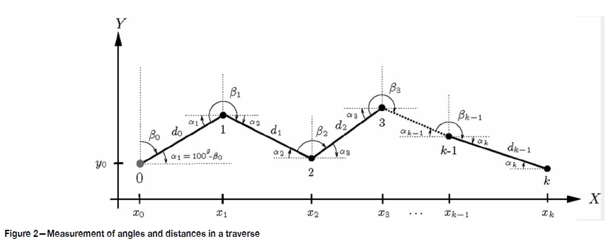
Consider a traverse based on a framework of coordinates as shown in Figure 2. Taking into account the propagation of errors in the measurement of angles (ßk) and distances (dk) along the traverse, the coordinates (xk,yk) of the last station k can be obtained. The initial station 0 = xoyo,) is treated as an error-free point, but the coordinates for any other point  are probabilistic and estimated as
 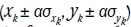 with a probability of 68.3% for a = 1, 95.5% for a = 2, and 99.7% for a = 3, where and are the standard deviations of Xk and yk, respectively.
By applying the theory of error propagation (Davis et al., 1981; Stiros, 2009), the coordinates (x, yk) for a point k have the following form:
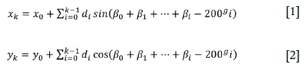
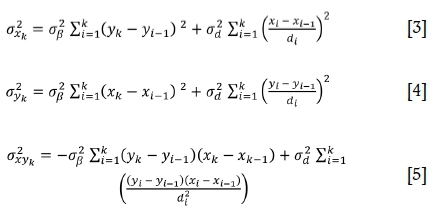
where β0 is measured clockwise from north. The angles β{, for i = 1,..., -1, are the horizontal angles between consecutive legs. Assuming that standard errors of angle and distance measurements satisfy  , respectively, the following variances and covariance of the coordinates (xk,yk) result:
Error ellipse
The variances and covariance allow any point k = (xk,yk) to be confined to an error ellipse with a certain probability. To do this, Equation [6] is applied:

with  and
and  computed in Equations [3] to [5]. Denote λ1, λ2 the roots of Equation [6]. Then, the semi-axes of the error ellipse are given by τλ1, τλ2, with a probability depending on τ. Thus, for τ = 1 the probability is 39%; for τ = 2.15 it is 90%, and for τ = 2.45 it is 99%. Moreover, the orientation of the error ellipse can be obtained as:
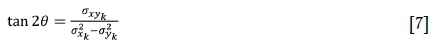
where θ is the angle between the major semi-axis and the X-axis (Mikhail, 1976).
Results
Errors in the measurements taken in the two shaft plumbing method
This method requires some operations to perform the connection survey that generate errors (Chrzanowski, Derenyi, and Wilson, 1967; Estruch and Tapia, 2003) as well as the overall error given by Equation [8]:
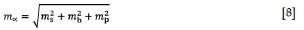
where mais the global error, msis the error produced in the surface works to determine the orientation and coordinates of the plumb at the surface, mbis the error from the underground topographic survey to connect both plumbs or between the plumbs, and mpis the vertical error of the plumb.
The surface traverse (Figure 3) between base C1-C2 and plumbs P1 and P2 was a closed traverse, which allowed calculation the total error due to the angular and linear errors in the polygonal axis. The polygon had the following characteristics:
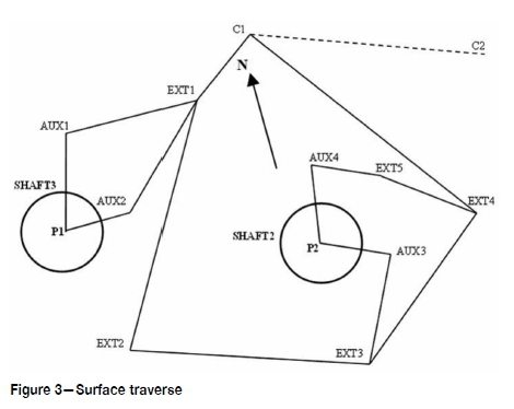
Length: 436.374 m
Number of legs: 5
Error in X: -0.0015 m
Error in Y: -0.0007 m.
The accumulation of angular and linear error in the axis, when the traverse was completed, produced a displacement of the final station (C1):

Coordinates of the plumbs (P1 and P2) were calculated through two different branches. Table II shows the error between measurements in each plumb.
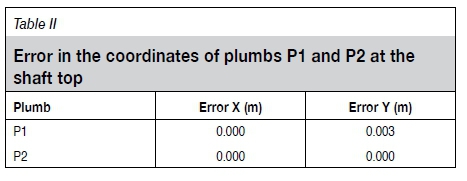
The real squared error of the base P1-P2 was:
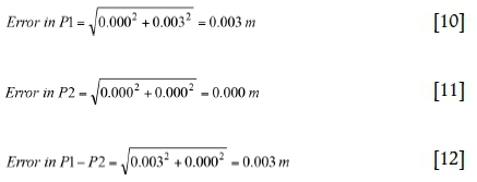
The small differences in the plumbs' coordinates, as well as the angular and linear errors in the exterior closed traverse, indicate the accuracy of these measurements because the real error in the exterior base P1-P2 was lower than the theoretical error. This theoretical error in bases P1 and P2 regarding the external survey was calculated taking into account the topographic instruments and the leg characteristics. Its value will be the quadratic sum of the error ellipses in the semi-axis per leg. These error ellipses were calculated according the methods used by Anderson and Mikhail (1998), Stiros (2009); and Mikhail (1976).
Error calculation (a) Error ms
Table III displays the error ellipse characteristics, at the end of the external survey, for plumbs P1 and P2, which were obtained by means of the topographical software TCP-MDT version 7.
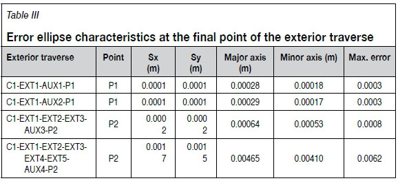
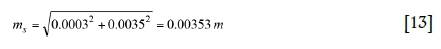
Hence, the maximum theoretical error in P1 and P2 coordinates due to the exterior measurements was:
P1 = 0.0003 m (average error between two legs)
P2 = 0.0035 m (average error between two legs).
Consequently, the total theoretical error of the base P1-P2:
As can be seen from the previous sections, the theoretical error is higher than the real error. The most unfavourable, the theoretical one, will be taken into account in the underground survey.
(b) Error mb
Figure 4 details the closed traverse (INT1-INT2-INT3-INT4-INT1) in the underground survey, used to transmit the coordinates of P1 and P2, which has the following characteristics and total errors:
Length: 187.270 m
No. of legs = 4
Total error in X = 0.0030 m
Total error in Y = -0.0015 m.
The angular and linear error accumulations in the different axes produced the next final station displacement:
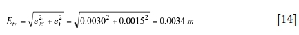
Table IV reveals the adequacy of the angular and linear errors in the closed underground traverse. The error determination was done following the same procedure as for the surface measurements.
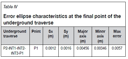
In this case, the maximum theoretical error in the base P1-P2 was, directly, the average error in the two legs of the underground traverse between P2 and P1, mb= 0.0057 m, which is larger than the real error obtained in the measurements of the closed traverse (INT1-INT2-INT3-INT4-INT1). Once again, it is considered the most adverse case.
(c) Error mp
The sources of error, mp, that could affect the verticality of the plumbs are quite complex and have to be thoroughly studied. These errors are especially important in the orientation transmission (a) because it is an angular measurement and the final linear error increases with the length of the traverse. Therefore, the plumbs have to be separated as far as possible in order to reduce the potential error. It is very difficult to do this with only one shaft, but in the case study the two shafts are separated by 100.618 m. This enables the angular error to be reduced significantly. The following paragraphs detail the factors that cause this error and the ways to calculate it and compensate for it, based on previous studies (Chrzanowski and Robinson, 1953; Chrzanowski, Derenyi, and Wilson, 1967). It was also demonstrated that the verticality of a plumbline in a shaft is affected by: ventilation, oscillation and vibration of the plumb, cross-sectional shape of the cable, and the effect of gravity.
Influence of ventilation
The air flow in an underground mine can produce a significant displacement in the verticality of the plumblines. Hence, it is essential to switch off the artificial ventilation system so as to minimize that the verticality error. The air speed dropped to 1.90 m/s at the bottom of Shaft 2 eight hours after the fans were switched off. Then, about 95% of the shaft entrance was covered, and consequently the air speed at the bottom was reduced from 1.90 m/s to 0.79 m/s. Two sets of 20 measurements were carried out, the first set with the shaft uncovered and the second with the shaft covered, two hours later. The air speed in Shaft 3 was reduced to 1.2 m/s at the bottom of the shaft 31 hours after the fans were stopped. Hence, the four sets of 20 measurements were done under similar conditions of air speed. Figure 5 details the relative position of both shafts and the flow direction in the ventilation circuit.
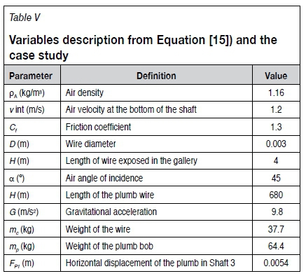
Mine ventilation is one of the main sources of error when using the plumbing method, and different procedures are used to compensate for this potential error. According to Chrzanowski (1967), the calculation of plumb displacement caused by ventilation has to take into account the air speed during the measurements in each shaft, depth of the shafts, plumb bob weight, and section of the shaft and tunnel, among other factors. Figure 6 shows how the ventilation varies the position of the plumb.
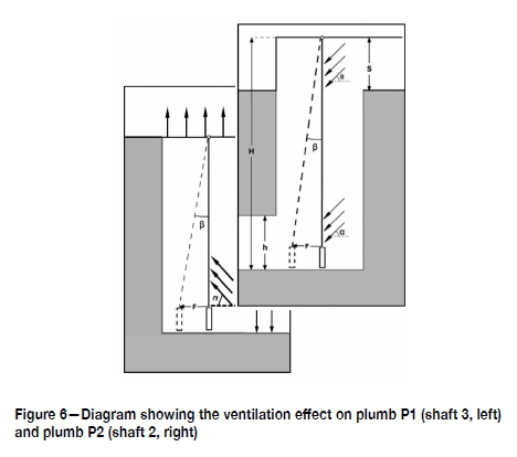
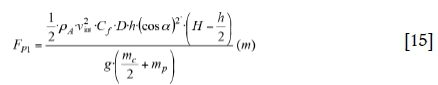
The equation for calculating Fp1is based on physical principles and it allows calculation of the plumb displacement owing to the ventilation (Figure 6). The calculation gave a horizontal displacement in plumb P1 of 5.4 mm (Table V).
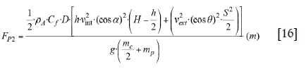
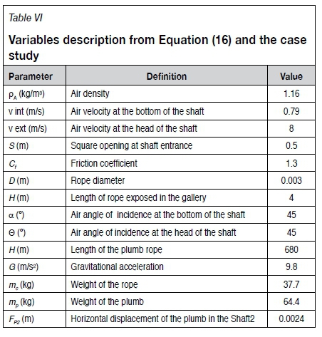
The covering of the shaft and its geometry affected the ventilation and, as a consequence, the plumb was also affected. The equation for calculating Fp2(Figure 6) has been used in this case. The angles θ and a created by the air and the horizontal can be determined graphically depending on the way the ventilation system introduces the air to the shaft and the intersection between the bottom of the shaft and the underground tunnel. However, a standard value of 45° can be adopted in the majority of the cases, as has been done in this survey. The deviation of plumb P2 was 2.4 mm (Table VI).
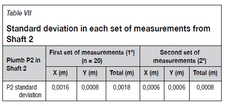
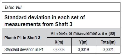
Fp1and Fp2values indicate the distance to compensate due to ventilation. However, it is necessary to know the direction and sense for the compensation. Previous studies indicated several methods that allowed the calculation of this direction, but they are laborious, complicated, and dangerous because employees have to work around the bottom of the shaft. Fortunately, the current surveying stations allow distances to be measured without the prism, after which the compensation is applied. The movement direction of the plumb in Shaft 2 was deduced from two points, 1° and 2°, obtained by the mean value of each set of measurements. There was an important air speed reduction between the first set of measurements (1.90 m/s) and the second (0.79 m/s once the shaft was covered). This reduction produced a displacement of 1 cm between both points. Tables VII and VIII display the standard deviation in each set according to several studies (Box and Hunter, 2005; Ebdon, 1985).
Once the displacement of P2 is calculated, its coordinates without the ventilation effect can be obtained. This point is called P2N and it was determined by means of the second set mean value, orientation, and horizontal displacement, FP2from Table VI. Finally, it was possible to calculate the new horizontal angle and distance towards P2 from the traverse station INT1.
Plumb P1 was determined by the procedure previously detailed, obtaining the average point P1N. Based on the coordinates from point P1N, the new horizontal angle and distance towards P1 from station INT3 of the underground traverse were calculated.
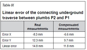
Table IX shows the linear error of the underground traverse with and without the ventilation compensation. It reflects a reduction of over 20% in the linear error, from 14.8 to 11.8 cm.
Hence, it is very important to take into account the compensation due to the ventilation effect in this kind of survey, particularly when it is not possible to cover the shaft or the natural ventilation is considerable. Besides, the angular and distance measurements have to be taken at the same time from the total station to the plumbs, and many times (two set of 20 measurements to plumb P2 in Shaft 2, and four sets of 20 measurements to plumb P1 in Shaft 3). For that purpose, it was necessary to use a laser capable of measuring the distance when aimed at a cable with a diameter of 3 mm from at least 10 m away.
Apart from the method described here, there are other options available such as applying a vertical load to the plumbs in order to reduce the ventilation effect (Schätti and Ryf, 2004).
Influence of plumb oscillation
The plumb was equipped with special wings to increase its stability. P2 measurements began five hours after the plumb bob was immersed in a tank full of oil. P1 measurements, on the other hand, started one hour after immersion. The centre point of the pendulum movement was found in both cases because of the number of measurements carried out.
Influence of vibrations and shape of the cable
Errors due to vibration and the shape (cross-section) of the cable were considered negligible because of several measures taken to reduce these: the wings, the tank of oil, and an anti-rotation cable.
Effect due to gravity and Earth's rotation
The distance between two plumbs varies slightly with depth because they are not exactly parallel, and if they were extended to the centre of the Earth they would converge under the influence of gravity. However, the existence of a centrifugal force changes the direction of the plumbs and they do not converge towards the centre of the Earth but towards another intermediate point as indicated in Figure 7 (Estruch, 2001; Martin, 1983).
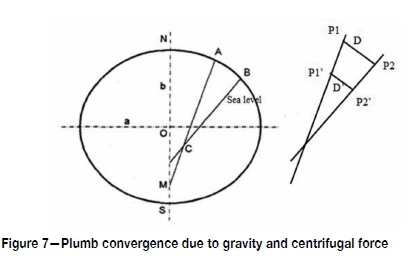
The distance in an alignment projection at a certain depth is deduced from the following equation
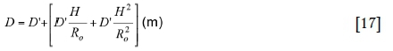
where D is the distance of the alignment in the surface (m), D' is the distance of the alignment in a certain depth (m), H is the depth of the projection of the surface alignment (m), and Rois the average radius of the Earth (6 375 000 m in this study).
Using the data from the case study, where D is 100.618 m and H is 680.591 m, D' will be 100.607 m with an error of 0.011 m. This error has been compensated by increasing each distance of the underground traverse between P1 and P2 by a value calculated applying the indicated equation according to previous studies by Chrzanowski and other authors. In this case, this error has been the most important. However, its compensation is very simple.
Other errors affecting the plumb verticality
Some authors consider the possibility that the plumbs could be affected in their displacement by their masses, but King and Habberjam (1951) stated that the attraction between the masses and the plumb is insignificant when the shaft is less than 1000 m deep. It is also said that the attraction of two plumbs is different if they are separated by more than 1500 m (King and Habberjam, 1951). As the plumbs in the case study were separated by 100 m at a depth of 680 m, the deviation due to the attraction between the plumbs and the ground does not influence the verticality, nor transmission of the orientation and cartographic system.
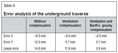
(d) Quality control
The closing error of the underground traverse between P2 and P1 has been used as a quality control in the survey. This linear traverse closing error in the traverse P2-INT1-INT2-INT3-P1 is an indicator of the global precision, because it accumulates the errors occurring on the surface and in the plumb verticality. Table X summarized the linear error of the underground traverse between the plumbs before and after applying the compensations.
Error Ma
All the errors that compose the plumb vertical deviation mpcould be compensated with the equations of Fp1and Fp2, achieving an error mppractically nullified. Therefore, the total error ma affecting the orientation from the base P1-P2 to the underground tunnel would be detailed as follows:
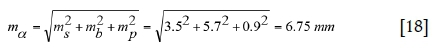
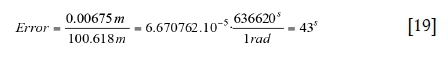
It was possible to find the angular error with the length of the base from the lineal error mα:
Errors in the measurements taken by the gyroscopic method
Errors in the orientation generated by the gyroscope depend on its precision. In this case, it has an accuracy of 60s in a single measurement according to the specifications of the supplier. However, a set of measurements can have a standard deviation about 40s as indicated in the section 'Two shaft plumbing method'.
Measurements done with the gyroscope consisted of two sets of measurements of the underground base INT3-INT2 on different days. Each set consisted of five measurements: three with the gyroscope located at the point INT3 measuring INT3-INT2 and two with the gyroscope located at INT2 measuring INT2-INT3.
Table XI shows the results and accuracy of the measurements. The standard deviation has been calculated according to the method of Box and Hunter (2005) and Ebdon (1985).
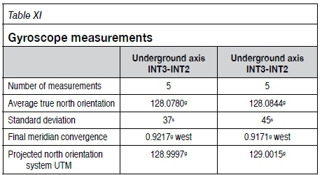
The mean value of base INT3-INT2 using the gyroscope was 129.0003g. The final meridian convergence is calculated from the theoretical meridian corrected by the data obtained from the calibration baseline (C4-C3). The theoretical meridian convergence in point of known coordinates is obtained by a software application from the Cartographic and Geological Institute of Catalonia website and equations by Estruch (2001). The convergence has been taken into account in determining the final orientation .
If only the gyroscopic method was applied, the coordinates of a known point would have to be projected to the underground tunnel from the surface using a conventional method, one plumb in a shaft for transmitting the cartographic system. Hence, there will be two sources of errors: the true north orientation to the underground base and the transmission of the cartographic system from the surface.
The error generated by the gyroscope affects the orientation of the base measured, while the errors of the cartographic system transmission have been described in the section 'Errors in the measurements taken in the two shaft plumbing method', but regarding only one plumb. The global error mais also determined by Equation [8].
Considering that the cartographic system is transmitted by plumb P1, the error in the surveying works on the surface according to the section 'Error ms' is 0.0003 m (Table XII). Therefore, msis 0.0003 m.
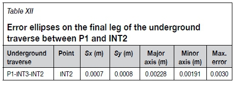
For calculating the error in the underground leg INT3-INT2 it is necessary to indicate that the underground traverse to find the coordinates of points INT3 and INT2 was the traverse P1-INT3-INT2. In short, only two legs. In this way the error ellipse in INT2 was as shown in Table XII.
Therefore, the maximum theoretical error of base INT2 in the underground topographic survey was, directly, the error in the leg of the underground traverse between P1 and INT2:
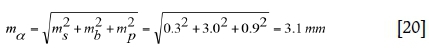
Overall, Equation [20] includes the error generated to transmit the cartographic system through plumb P1 to the base INT3-INT2:
It must be pointed out that this error does not affect the orientation of the baseline INT3-INT2; it only produces a displacement of the coordinates. The error in the orientation is the standard deviation, 41s, of the measurements done by the gyroscope.
Discussion
The underground orientation of the base INT3-INT2 varies because of the ventilation compensation, but it is not affected by the gravity force compensation (Table XIII). It can also be observed that the difference between both methods is only 44s after the compensations.
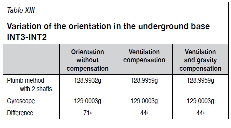
Both methods have advantages and disadvantages, but they have similar accuracies.
➤ The two shaft plumbing method is operationally more laborious than the gyroscopic alternative. It needs to transmit the orientation and cartographic system from two shafts, whereas the gyroscope needs only one. This fact necessitates several hours of work around the shafts, increasing the risk to the staff.
➤The plumbing method also needs more surface and underground surveying. However, the closed traverse in this method allows the accuracy of the values to be checked, whereas with the gyroscope the results can be verified only by doing an extra set of measurements.
➤The most dangerous measurements are those around the shaft, especially those at the shaft bottom to calculate the central position of the plumb during its pendulum movement, due to falling rocks and other objects. However, the use of a total station without prism avoids this situation.
➤Despite the plumbing method takes a few hours longer than the gyroscopic option, in the case study the plumbing took 20 hours and the gyroscopic measurements 31 hours. This discrepancy is due to the verification measurements done in the second case, while the two shaft plumbing method does not need verification. This time is subdivided into the following operations:
• Plumbing method: 20 hours
a) 11 hours in Shaft 2
b) 9 hours in Shaft 3
• Gyroscope: 31 hours with verification measurements and 19 hours without them
a) 7 hours in Shaft 3 (work for transmitting the cartographic system from the exterior to underground in the case that the two shaft method was not applied)
b) 2 χ 5 hours calibration base C4-C3 and verification
c) 2 χ 7 hours underground measurement INT3-INT2 and verification.
Conclusions
The study has described some adaptations of existing procedures, applied in studies some time ago, by means of new technologies, improving the accuracy of the measurements and safety levels during the survey because of the shorter time spent working around the shafts. In addition, the two shaft plumbing and the gyroscopic method have been analysed, emphasising the characteristics of both options. The comparison revealed similar accuracy levels, with a difference of only 44s between the two methods. This confirms the reliability of the measurements made in the study and the suitability of both options.
The study suggests that the most important source of error in the two shaft plumbing method is the ventilation factor. Therefore, it is important to stop the artificial ventilation at least 24 hours before taking the measurements to reduce the air flow as much as possible. Unfortunately, it is very difficult to stop the operating fans for such a long time, and covering the intake shaft is an alternative. It is still necessary to compensate for the deviation of the plumb due to the ventilation effect caused by the remaining air flow.
It has also been found necessary to compensate the projected distances for a certain depth because of gravity and rotational forces, achieving a reduction in the linear error of the traverse between plumbs in both shafts in large part. Although this is very important in terms of error, compensation is much easier than in the ventilation effect.
The conventional plumbline method has proven to be a good choice when there are two shafts with depths greater than 500 m, and with some of the problems within the shaft as detailed in the paper: pollutants, dust, remaining air flow, the possibility of rocks and other objects falling, water, limited physical space, and temperature and pressure changes during the measurement period. All these elements are potential sources of error in the verticality of an optical plumb as well as an avoidable occupation hazard. In the other cases the optical plumb is an adequate alternative due to its speed of installation.
It can be concluded that the conventional plumb method combines higher precision measurements and safer working conditions than the optical plumb method in the case study conditions. In addition, the combination of both methods, gyroscopic and plumbing, has been verified as an appropriate approach when high-precision measurements are needed.
Acknowledgements
The authors would like to thank ICL Iberia for their cooperation, especially the head of the surveying department, as well as the technical support of Carles Xandri from Maptek Pty Ltd.
References
Anderson, J. and Mikhail, E. 1998. Surveying, Theory and Practice. 7th edn. WCB/ McGraw-Hill, Boston. [ Links ]
Bahuguna, P.P. 2003. Correlation survey for shaft deepening in Digwadih underground coal mine. Journal of Surveying Engineering, vol. 129, no.1. pp. 33-36. [ Links ]
Benecke, N. and Kalz, U. 2006. Ensuring tunnel navigation by cost-effective gyroscope control measurements, Tunnelling and Underground Space Technology, vol. 21. p. 253. [ Links ]
Box, G.E.P., Hunter, J.S., and Hunter, W.G. 2005. Statistics for Experiments. Design, Innovation and Discovery. Wiley, Hoboken, NJ. [ Links ]
Chrzanowski, Α., Derenyi, E., and Wilson, P. 1967. Underground survey measurements: Research for progress. Canadian Mining and Metallurgical Bulletin, vol. 60, no. 662. p. 643. [ Links ]
Chrzanowski, Α. and Robinson, Α. 1953. Surveying, Theory and Practice. McGraw- Hill, New York. [ Links ]
Davis, R., Foote, F., Anderson, J., and Mikhail, E. Surveying. Theory and Practice (sixth ed.), McGraw-Hill, 1981. [ Links ]
Ebdon, D. 1985. Statistics in Geography. Blackwell. Hoboken, NJ. [ Links ]
Estruch, M. and Tapia, Α. 2003. Topografia Subterránea para Minería y Obras. Ediciones UPC, Barcelona. [ Links ]
Estruch, M. 2001. Cartografía Minera. Ediciones UPC, Barcelona. [ Links ]
King, H.J. and Habberjam, G.M. 1951. Displacement of Shaft Plumb Lines. Colliery Engineer, London. [ Links ]
Martín, F. 1983. Geodesia y Cartografía Matemática. Paraninfo S.A., Madrid. [ Links ]
Mikhail, E.M. 1976. Observations and Least Square. IEP, New York. [ Links ]
Schätti, I., and Ryf, Α. 2004. Hochpräzise Lotung im Schacht Sedrun des Gotthard-Basistunnels. Proceedings of the 14th International Conference on Engineering Surveying, Zurich. http://doi.org/10.5169/seals-236146 [ Links ]
Shi, Ζ., Ma, J., and Yang, Z. 2016. A study on the optimized adjustment method of maglev gyro control traverse under non-weighted measurement in long and large tunnels, Modern Tunnelling Technology, vol. 53, no. 2. pp. 44-47. [ Links ]
Staley, W.W. 1964. Introduction to Mine Surveying. Stanford University Press. [ Links ]
Stiros, S.C. 2009. Alignment and breakthrough errors in tunneling. Tunnelling and Underground Space Technology, vol. 24. pp. 236-244. [ Links ]
Stroner, Μ., Michal, 0., and Urban, R. 2017. Maximal precision increment method utilization for underground geodetic height network optimization. Acta Montanistica Slovaca, vol. 22, no. 1. pp. 32-42. [ Links ]
Taton, R. 1966. Topographie Souterraine. Editions Eyrolles, Paris. [ Links ]
Urban, R. and JiRikovský, Τ. 2015. Accuracy analysis of tunneling measurements in UEF Josef. Proceedings of the 15th International Multidisciplinary Scientific GeoConference, SGEM, Sofia, vol. 2, no. 2. pp. 35-42. [ Links ]
Van Cranenbroeck, J. 2010. Controlling vertical towers. Reporter 63: The Global Magazine of Leica Geosystems. pp. 29-31. [ Links ]
Yao, Υ., Lu, N., Yang, Υ., Cao, Υ., and Yu, H.S. 2019. Study of long-termed displacements of a tunnel boring machine during its stoppage. Tunnelling and Underground Space Technology, vol. 84. pp. 432-439. [ Links ]
Zamecnikova, Μ., Wieser, Α., Woschitz, Η., and Ressl, C. 2014. Influence of surface reflectivity on reflectorless electronic distance measurement and terrestrial laser scanning, Journal of Applied Geodesy, vol. 4. pp. 311-325. [ Links ]
Zhang, X., Zhang, Υ., Li, B., and Qiu, G. 2018. GNSS-based verticality monitoring of super-tall buildings. Applied Sciences, vol. 8, no. 6. doi:10.3390/app8060991 [ Links ]
 Correspondence:
L. Sanmiquel
Email: alluis.sanmiquel@upc.edu
bmarc.bascompta@upc.edu
cjosep.maria.rossell@upc.edu
Received: 10 Jul. 2019
Revised: 5 Nov. 2019
Accepted: 29 Nov. 2019
Published: February 2020

