


Services on Demand
Article
 English (pdf)
 Article in xml format
 Article references
Indicators

Related links
-
 Cited by Google
 -
 Similars in Google
Share

 Permalink
Journal of the Southern African Institute of Mining and Metallurgy
On-line version ISSN 2411-9717
Print version ISSN 2225-6253
J. S. Afr. Inst. Min. Metall. vol.120 n.2 Johannesburg Feb. 2020
http://dx.doi.org/10.17159/2411-9717/878/2020
HEAVY MINERALS PAPERS
Design of sidewall lining/cooling systems for AC or DC ilmenite smelting furnaces
H. JoubertI; H. KotzéII
ITenova Pyromet, Midrand, South Africa
IIConsensi Consulting, Mtunzini, South Africa
SYNOPSIS
Ilmenite smelting is well established using both direct current and alternating current furnaces. Regardless of the furnace type, the slag produced is aggressive towards the sidewall lining. The formation of a stable slag freeze lining is essential to arrest lining wear and ensure an acceptable furnace campaign life. The sidewall lining can be severely damaged within a short period of time under upset conditions and without a stable freeze lining in place. The sidewall lining/cooling system adjacent to the furnace slag bath must be designed to ensure a stable freeze lining and prevent lining wear under normal as well as upset conditions. In this paper we explore the effectiveness of high-intensity copper coolers compared to the more traditional magnesia working lining combined with an externally cooled furnace shell. An increase in furnace heat losses has been raised as a concern for intensively cooled sidewalls. The estimated furnace heat losses are compared for the different lining/cooling system designs.
Keywords: ilmenite smelting, AC furnace, DC furnace, sidewall cooling, freeze lining.
Introduction
Ilmenite is smelted in both direct current (DC) and alternating current (AC) furnaces to produce titania-rich slag and pig iron (Kotzé, Bessinger, and Beukes, 2006; Gous, 2006; Williams and Steenkamp, 2006). The slag is the main product and is primarily used as a feedstock for the production of TiO2 pigment (Kahn, 1984).
As described by MacPherson (1982), the slag produced in ilmenite smelting is extremely aggressive towards the furnace lining and no known refractory material can withstand the slag attack. The formation of a frozen slag layer or freeze lining is essential to protect the furnace lining and maintain sidewall integrity. The slag superheat must be controlled to prevent the rapid destruction of the freeze lining, and subsequently the refractory lining. Pistorius (2004) estimated that a 130 mm thick freeze lining can be worn away within 15 minutes if the feed to the furnace is terminated while the power input is maintained. In contrast, it will take much longer to re-form the freeze lining. Part of the reason for the aggressive nature of ilmenite smelting slag is its low viscosity at temperatures above its liquidus temperature, resulting in a remarkably fluid slag with a high convective power (Handfield and Charette, 1971).
A typical ilmenite smelting furnace working lining consists of high-quality magnesia refractory bricks. Magnesia bricks are used owing to their resistance at high operating temperatures and relatively high thermal conductivity (assumed 5.9 W/mK), which helps establish a freeze lining. Another reason for maintaining the freeze lining is to avoid potential slag contamination by magnesia (MgO) due to refractory wear (Kotzé, Bessinger, and Beukes, 2006).
In this paper, we explore the use of an alternative lining/cooling system which will maintain a competent freeze lining in ilmenite smelting furnaces. A freeze lining is considered competent when it is thick enough to maintain structural stability, typically at least 20 mm thick, and this thickness is maintained across all operating conditions. Key criteria considered in evaluating the furnace lining/ cooling system include its ability to form and maintain a competent freeze lining under normal as well as upset operating conditions, prevent slag contamination, reduce metal penetration and wear in the critical slag-metal tidal zone, improve monitoring of the freeze lining and slag bath conditions, and limit heat losses from the furnace. Coetzee et al. (2007) proposed the use of a carbon-based lining to achieve a more stable freeze lining in an ilmenite smelting furnace. We propose the use of intensive sidewall copper cooling as an alternative. The proposed lining/ cooling system design is evaluated considering the key criteria listed above. A comparison is made with a typical lining design consisting of high-quality magnesia bricks in the working lining.
Proposed sidewall lining/cooling system design
The proposed lining/cooling system design consists of high-intensity copper coolers installed in the sidewall adjacent to the slag bath. The proposed arrangement is shown in Figure 1. It includes Tenova's high-intensity MAXICOOL® sidewall cooler designed to operate at hot face fluxes of up to 500 kW/m2. The height and location of the high-intensity cooler are determined by evaluating the expected maximum metal and slag bath levels in the furnace. Safety margins for both maximum slag bath level and metal bath level are considered. For the safety margin between the metal bath level and the bottom of the cooler, a safety margin equal to at least 24 hours of production without tapping above the normal maximum metal level is considered appropriate. This is to prevent superheated molten metal from contacting and damaging the copper cooling element. It is important to note that ilmenite smelting furnaces, and in particular the furnace arrangement considered, are stationary and do not tilt.
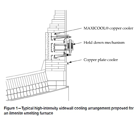
The MAXICOOL® cooler's cast copper body consists of a hot face star pattern to retain frozen slag more securely and cast-in Monel piping for the cooling water. Two cast-in cooling circuits run in parallel throughout the cooler. The cooler is designed to operate safely with only one circuit in the event that cooling water supply is lost to one of the circuits. All cooling water connections remain external to the furnace shell. A steel frame incorporating special friction joints, and a single hold-down spring mechanism per cooler connects the cooler to the furnace shell through four locating bolts. The hold-down mechanism ensures sufficient pressure is maintained on the lower sidewall lining to prevent metal penetration through horizontal joints, even during furnace cool-down periods. Each cooler is fitted with cast-in thermocouples extending past the hot face of the cast-in cooling pipes. For furnace start-up a sacrificial monolithic refractory lining is cast on the hot face of each cooler. Vertical lap joints between adjacent coolers ensure that there is no through path for superheated slag.
As shown in Figure 1, a single row of copper plate coolers with cooling water channels external to the furnace shell is incorporated in the lining below the high-intensity cooler. This is to provide deep cooling in the critical metal-slag tidal zone while eliminating the risk of metal making contact with cooling water. The copper plate coolers are fitted with thermocouples extending close to the cooler hot face.
Sidewall heat load and evaluation
The evaluation of the lining/cooling system design, with and without intensive sidewall cooling, depends primarily on the slag bath superheat and the convective heat transfer between the slag bath and the sidewall. In turn, both parameters depend on the operating conditions and the slag composition. The operating conditions, in particular the ilmenite feed to input power ratio (IPR), determine the bulk slag temperature that influences the slag superheat. The slag composition affects the slag properties that determine the bath to sidewall heat transfer coefficient, including the molten slag thermal conductivity, viscosity, expansion coefficient, liquidus and solidus temperatures, and in turn the slag freezing temperature. The slag properties, in particular the slag viscosity, are a function of the IPR as well as the selected feeding regime. The feeding regime is primarily determined by the reductant (normally anthracite) to ilmenite feed ratio (AIR) (Pistorius, 1999). Depending on the furnace design, size, and operating mode, the bath to sidewall heat transfer coefficient can be affected by forced convection due to phenomena such as arc thrust, as is likely the case for AC furnaces (Timm, 2006; Stenkvist, 1984). In addition, the slag composition affects the thermal conductivity of the frozen slag.
In this paper, natural convection next to the sidewall is considered for the calculation of the heat transfer coefficient between the bath and the sidewall hot face. The Nusselt number used in the calculation of the heat transfer coefficient is based on an empirical relationship developed for slag bath furnaces (Kang, 1991; Joubert, 2000). The effect of arc thrust on the bath flow patterns and the convective heat transfer adjacent to the furnace sidewall is not considered in this paper. If arc thrust is present, it is expected to enhance the convective heat transfer adjacent to the sidewall.
Operating conditions and slag properties
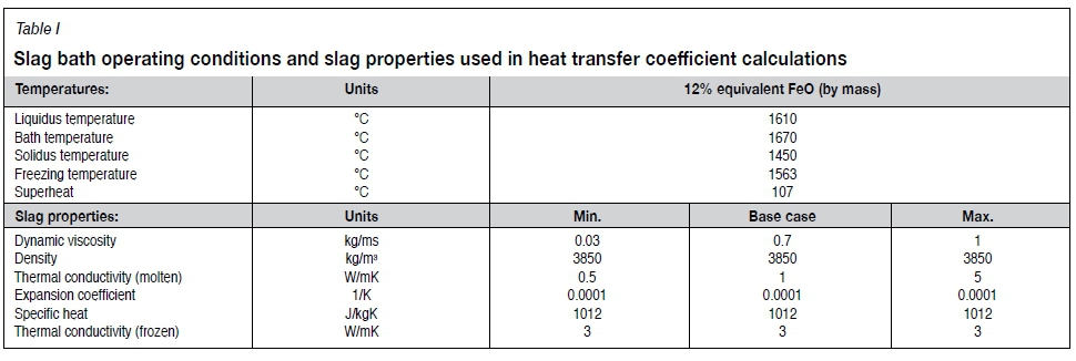
Table I lists the slag bath operating conditions and slag properties considered in the calculation of the bath to sidewall convective heat transfer coefficient. A slag with an equivalent FeO content of 12% by mass is considered. The slag liquidus temperature is calculated based on work done separately by Kotzé (2019) considering equivalent FeO content. The slag bath temperature is considered to be 60°C above the slag liquidus temperature. The slag solidus temperature is calculated using an empirical relationship considering equivalent FeO content (Kotzé and Pistorius, 2010). Typically, the slag freezing temperature is calculated as the average between the liquidus and solidus slag temperatures (Joubert and McDougall, 2019). Considering that the viscosity increases rapidly around the liquidus temperature for ilmenite furnace slags (Handfield and Charette, 1971; Hu et al., 2018), the freezing temperature is assumed to be closer to the liquidus temperature and is calculated as the solidus temperature plus 80% of the difference between the liquidus and solidus temperatures. The slag superheat is calculated as the difference between the slag bath and the slag freezing temperatures.
The dynamic viscosity for typical ilmenite smelting slags has been measured and is reported to be 0.03 kg/ms (Handsfield and Charette, 1971) and 0.06 kg/ms (Hu et al., 2018). In both studies, the viscosity was found to remain remarkably constant at temperatures above the liquidus temperature. However, both studies considered a fully molten slag without any iron droplets, crystallization, or other solid inclusions. The presence of these solid inclusions is what gives rise to the slag foaming typically encountered in ilmenite smelters and it is therefore considered that the effective viscosity will be higher than for fully molten slag (Pistorius and Coetzee, 2003; Roscoe, 1952). Viscosity measurements of slag with inclusions are not possible using the typical measurement equipment, and no such data could be found. Considering this, a range of viscosities is used in the calculations with an effective viscosity of 0.7 kg/ms assumed for the typical case (see Table I).
Dingwell (1991) reported the density of pure liquid TiO2 to range between 3270 and 3300 kg/m3 for the range of slag bath temperatures considered. Based on separate work by Kotzé (2019) on TiO2 -Ti2O3 -FeO melts, it was decided to use a density of 3850 kg/m3 for the purpose of calculating the heat transfer coefficient.
The thermal conductivity of the molten slag affects the slag to sidewall heat transfer coefficient through the Prandtl number as well as directly in the calculation of the coefficient from the Nusselt number. A thermal conductivity value of 1 W/mK was proposed by Pistorius (2004) for frozen slag and by Zietsman and Pistorius (2004) for molten slag. As the thermal conductivity of the molten slag has a significant influence on the calculated heat transfer coefficient, a range is proposed in Table I with the typical value equal to 1 W/mK. The maximum value of 5 W/mK is based on the measured thermal conductivity of frozen slag at 1400°C by Heimo (2018). This value is considered as an extreme.
A molten slag volumetric expansion coefficient of 1 χ 10-4 m3/m3K is used to calculate the Grashof number (Kang, 1991). The specific heat of the slag bath is calculated using an empirical relationship based on equivalent FeO (Kotzé and Pistorius, 2010). Finally, the thermal conductivity of the frozen slag layer is assumed to be 3 W/mK. The effect of the frozen slag conductivity is limited to determining the slag freeze lining thickness, if formed, and the conductivity has little influence on the sidewall hot face temperature and heat flux (Joubert and Mc Dougall, 2019).
The slag bath temperature, freezing temperature, and slag superheat for the base case are used in the heat transfer calculations. The heat transfer coefficient is calculated across the range of slag viscosities and molten slag thermal conductivities to evaluate its sensitivity.
Calculation results
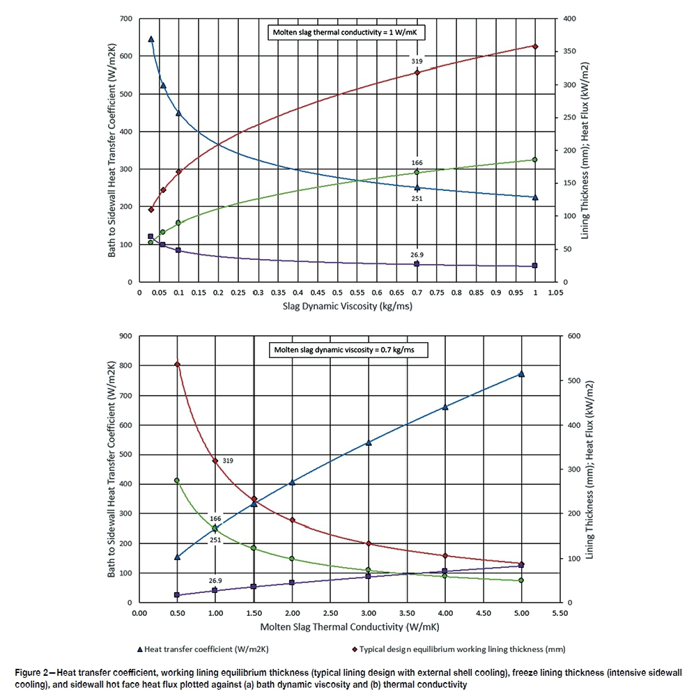
The results of the calculations are shown in Figure 2. The calculations and results are limited to the sidewall slag bath zone. The results include the calculated heat transfer coefficient, the equilibrium working lining thickness for a lining based on a typical magnesia refractory lining design with external shell cooling, and the freeze lining thickness if intensive sidewall cooling is employed. For the typical refractory lining design, the equilibrium working lining thickness represents the worn lining thickness at which the hot face temperature will be equal to the slag freezing temperature. Further wear of the lining will occur only if the bath operating conditions or slag properties change for the worse.
In Figure 2a the results are plotted against the range of slag bath dynamic viscosity values listed in Table I. The thermal conductivity of the molten slag bath is maintained at the base case value of 1 W/mK. The bath to sidewall heat transfer coefficient decreases with increasing viscosity, while the equilibrium working lining thickness for the typical lining design, as well as the freeze lining thickness for the intensive sidewall cooling design, increase. The base case values are labelled on the graph in Figure 2a for reference.
In Figure 2b the results are plotted against the range of molten slag thermal conductivity values listed in Table I. The slag bath viscosity is kept constant at the base case value of 0.7 kg/ ms. The bath to sidewall heat transfer coefficient increases with increasing bath thermal conductivity. The equilibrium working lining thickness for the typical lining design, as well as the freeze lining thickness for the intensively cooled design, decrease with increasing bath thermal conductivity. The base case values are labelled on the graph in Figure 2b for reference.
The first observation from the results is that for the base case, 0.7 kg/ms viscosity and 1 W/mK molten slag thermal conductivity, the equilibrium working lining thickness for the typical refractory lining design is calculated to be 319 mm. This is at the limit of maintaining a stable working lining and any adverse deviations in operating conditions and slag properties
could result in lining failure. For the same base case the freeze lining thickness on the hot face of the intensive sidewall cooling system is calculated to be 166 mm. This is considered a very competent freeze lining thickness.
The second observation is that for the minimum viscosity of 0.03 kg/ms, as measured for fully liquid slag by Handsfield and Charette (1971), the equilibrium lining thickness is calculated to be 109 mm (Figure 2a), which is considered unsustainable. For the same load case the freeze lining thickness developed on the hot face of the intensive sidewall cooling will reach equilibrium at 60 mm, which is a competent freeze lining thickness. As noted previously, freeze lining thickness is directly proportional to the thermal conductivity of the frozen slag (Joubert and Mc Dougall, 2019). If the thermal conductivity is assumed to increase from 3 W/mK to 5 W/mK considering the operating temperatures (Heimo, 2018), the freeze lining thickness will increase to approximately 101 mm.
A parameter that has not been varied in the calculations is the slag superheat. As noted by MacPherson (1982), the slag cannot be allowed to attain significant superheat as this will result in the rapid destruction of the freeze lining and subsequent wear of the refractory lining. Considering the base case viscosity and thermal conductivity, and lowering the superheat from 60°C to 30°C above the slag liquidus, the equilibrium lining thickness for the typical refractory design will increase from 319 mm to 507 mm. Increasing the superheat to 90°C results in a reduced equilibrium lining thickness of 224 mm. The calculation results confirm that the equilibrium lining thickness of a typical refractory lining design is sensitive to the slag bath superheat, assuming all other parameters remain unchanged. If the same changes in the slag superheat are applied to the calculations for the intensively cooled sidewall design, the calculated equilibrium freeze lining thickness varies between 260 mm and 119 mm compared to the base case 166 mm. In all cases a competent freeze lining is maintained on the hot face of the lining/cooling system.
As noted, the calculations are based on natural convection between the bath and the sidewall hot face. For AC furnaces the heat transfer coefficient may be higher considering the forced convection effect that is likely to be induced by the arc thrust. This differentiates AC from DC furnaces, where arc thrust is not a significant contributor.
Lining/cooling system integrity
The campaign life of a furnace lining is determined by extreme or upset conditions, and not by the normal operating conditions (Joubert, 1997). Severe lining wear can occur during a short period of upset conditions. This is true for all furnace operations, and in particular for ilmenite smelting where the typical refractory lining is subjected to high bath temperatures and aggressive chemical attack (Garbers-Craig and Pistorius, 2006).
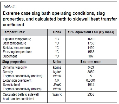
The extreme case listed in Table II is used to evaluate the lining/cooling system integrity. The extreme case considers the base case slag composition combined with the minimum slag viscosity and the maximum molten slag thermal conductivity. The bath operating temperature is increased to 1750°C, resulting in a bath to freezing temperature superheat of 187°C.
Applying the extreme condition to the typical refractory lining design for ilmenite furnaces, it is calculated that the working lining will be worn away completely. In fact, equilibrium is calculated to be achieved halfway through the expansion layer typically installed between the refractory lining and the externally cooled furnace steel shell.
For the intensively cooled sidewall design, the extreme condition results in an average equilibrium freeze lining thickness of 4 mm on the hot face of the copper cooler. The equilibrium heat flux under extreme conditions is calculated to be 441 kW/m2. The extreme case is not considered a viable long-term operating condition as the heat losses will be too high. The purpose of considering the extreme case is to evaluate the lining integrity under extreme conditions that may occur for short periods during the furnace campaign. It is calculated that the typical refractory lining design will not withstand such extreme conditions, and exposure for only short periods of time will severely damage the lining.
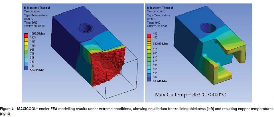
To evaluate the integrity of the intensive sidewall cooler considering the extreme case, a more detailed 3D FEA model is used. The model is shown in Figure 3. The model represents a symmetrical MAXICOOL® cooler section. The extreme case bath temperature of 1750°C is applied to the model hot face through the calculated bath to sidewall heat transfer coefficient of 2356 W/m2K. A transient thermal analysis is performed with nonlinear properties for the slag bath to calculate the freeze lining formation on the hot face. The results are presented in Figure 4.
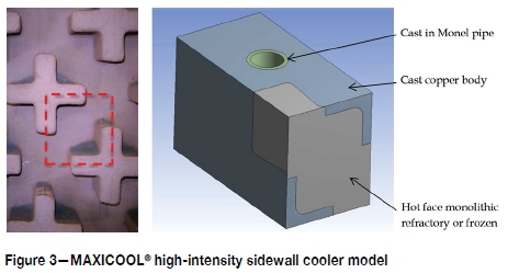
The freeze lining thickness stabilizes at approximately 8 mm in front of the slag-retaining copper stars' hot face, and at a thickness less than or behind the hot face of the copper stars in the pockets between the copper stars. This result compares well with the calculated average equilibrium freeze lining thickness of 4 mm. Under these extreme conditions, the maximum copper temperature is calculated to be 353°C, which is below the 400°C limit Tenova Pyromet aims for during the design of copper sidewall coolers to ensure structural integrity of the cooler is maintained.
The main observation from these results is that the intensively cooled sidewall design will maintain its integrity under these extreme operating conditions. A thin freeze layer will be maintained on the copper cooler hot face and the maximum copper temperatures are below the design limit to ensure structural integrity is maintained. The typical refractory lining design used for ilmenite furnaces will not be able to maintain its integrity under these extreme conditions.
Slag-metal tidal zone
For any furnace the sidewall slag-metal tidal zone is one of the most important and difficult areas to design. The lining/cooling system hot face is exposed to both metal and slag. As such the lining is exposed to the more aggressive wear mechanisms associated with the slag, while the use of intensive sidewall cooling is not advised as it may come in contact with molten metal, which can lead to failure.
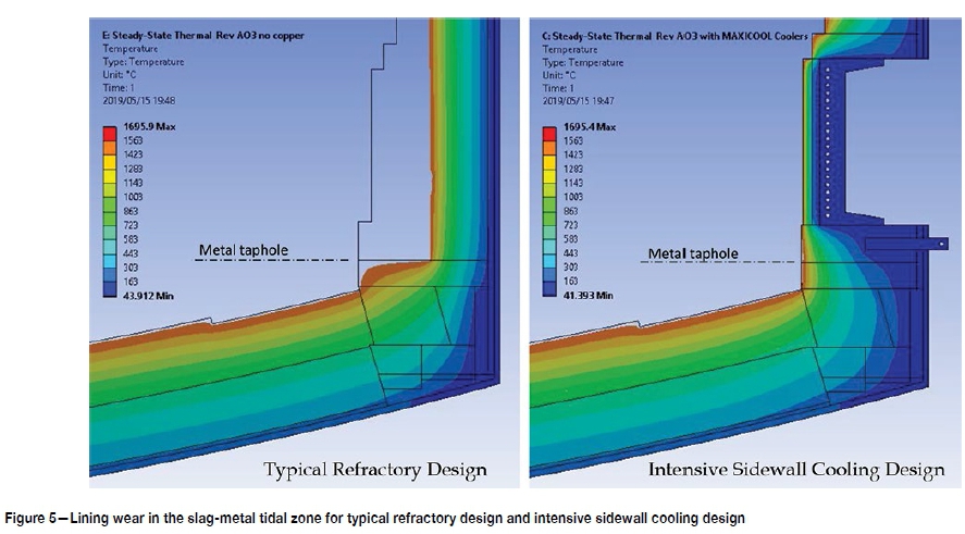
For the purpose of evaluating the slag-metal tidal zone the base case slag composition, slag viscosity (0.7 kg/ms), and molten slag thermal conductivity (1 W/mK) are considered. As for the extreme case, a bath operating temperature of 1750°C is considered, resulting in a bath to freezing temperature superheat of 187°C. A 2D axisymmetric, thermal steady-state FEA model with nonlinear material properties is employed. For the working lining the equilibrium lining thickness is calculated considering a slag freezing temperature of 1563°C as for the base case slag composition in Table I. For the purpose of the evaluation it is assumed that all metal is tapped until slag appears. In other words, the lower sidewall hot face is exposed to the slag bath from the metal tap-hole level upwards. The results for the typical refractory lining design and the high-intensity sidewall cooling design are shown in Figure 5.
For the typical refractory lining design, the extensive working lining wear profile will extend down to the metal tap-hole level. For the intensive sidewall cooling design, the working lining wear below the MAXICOOL® cooler will be minimal, with only slight wear shown on the hot face directly above the metal tap-hole. This is due to the cooling effect from the MAXICOOL® cooler above and the copper plate cooler behind the slag-metal tidal zone, ensuring the equilibrium lining thickness is close to the original lining thickness.
The main observation is that the intensive sidewall cooling design will better maintain the sidewall integrity adjacent to the slag bath, as well as the working lining integrity in the critical slag-metal tidal zone. In addition, the spring-loaded hold-down mechanism will help prevent metal penetration into the lower sidewall lining. By maintaining pressure on the lower sidewall, it prevents horizontal gaps from opening up due to contraction of the refractory bricks during cool-down periods. This will further enhance the working lining integrity in the slag-metal tidal zone. Even though the modelled area does not include the actual metal tap-hole, the intensive sidewall cooling design will be advantageous in maintaining the integrity of the metal tap-hole area in the long run.
Heat losses
Under steady-state conditions the heat flux, and therefore the heat loss, through the slag sidewall working lining will be the same for the typical refractory lining design and the proposed high-intensity sidewall cooling design. As per Equation [1], once steady state is reached, either due to refractory wear up to the point where the hot face temperature is equal to the slag freezing temperature or when a stable freeze lining is formed, the heat flux is a function of the bath temperature, the slag freezing temperature, and the heat transfer coefficient between the bath and the sidewall hot face. As such, under steady-state conditions, the slag sidewall heat losses will be a function of the operating conditions and slag chemistry, or physicochemical properties, and not a function of the lining/cooling system design.

Overall heat losses will, however, be higher for the high-intensity sidewall cooling design due to the exposed cooler area above the slag bath. The height of this area depends on the safety margin allowed for and the actual operating bath level. Typically, a design safety margin of approximately 300 mm is included above the maximum expected bath level. The additional heat losses are limited and expected to be in the order of 5% of the overall furnace heat losses.
The initial heat losses until equilibrium is reached will be higher for the intensively cooled sidewall design. However, the heat losses will change less over the campaign life of the furnace as there is no significant lining wear adjacent to the slag bath.
Under extreme conditions the heat losses will increase more rapidly for the intensively cooled sidewall design. This is desirable for two reasons. Firstly, the higher heat removal rate is required to re-establish steady state, maintain the freeze lining, and ensure the sidewall integrity under extreme conditions. Secondly, the rapid increase in heat losses will assist in the more responsive monitoring of the bath conditions under extreme conditions, as described in the next section.
Monitoring
Apart from protecting the furnace lining, it is important to maintain a stable freeze lining on the sidewall of ilmenite furnaces as it forms a critical part of the overall bath smelting process as well as the process control (Pistorius, 1999, 2004). Monitoring of the freeze lining condition and any upset bath conditions are therefore critical in ilmenite smelting. The most obvious and widely used monitoring method is by thermocouples installed in the sidewall refractory lining. The depth of installation is limited by the maximum allowable operating temperature of approximately 1200°C for the typically used Type K thermocouples. As a consequence, the thermocouples are not responsive to changes in bath conditions and freeze lining thickness due to the thermal inertia or specific heat of the refractory lining between the thermocouple and the lining hot face (Zietsman, 2004).
The intensively cooled sidewall design and the use of copper coolers allow more rapid monitoring of changes in bath conditions and the freeze lining thickness. Thermocouples are installed close to the hot face of the copper cooling elements, reducing the distance to the freeze lining. In addition, the copper between the thermocouple and the freeze lining has a lower specific heat and a significantly higher thermal conductivity compared to magnesia refractory material. As a result, thermocouple temperature measurements will respond more rapidly to changes in the bath conditions and freeze lining thickness.
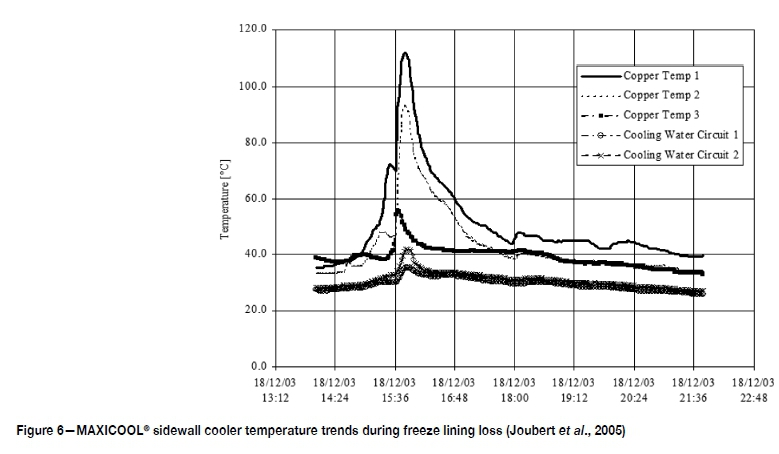
As an example, on a slag cleaning furnace operating at bath temperatures in excess of 1600°C and equipped with high-intensity MAXICOOL® sidewall coolers, an upset condition was experienced adjacent to the sidewall (Joubert et al., 2005). During the event, a sudden rise or jump in the copper cooler temperatures occurred on one of the coolers, eventually triggering the high-level alarms (see Figure 6). The cooling water outlet temperatures increased as well. On inspection it was noticed that the freeze layer that formed on the hot face of the cooler had collapsed. The copper star pattern on the hot face of the cooler was visible through an inspection port. Thermocouples were installed on three levels inside the cooler body. The thermocouple that responded first and showed the highest increase in temperature was the closest to the location of the collapsed freeze layer. The other thermocouples responded as well, but slower and with a lower temperature increase. The furnace was kept operating and within approximately 3 hours the freeze layer reformed and full equilibrium was re-established.
The main observation here is that the number and location of thermocouples in the copper coolers can be selected based on the expected operating bath levels to monitor local conditions and detect events.
Conclusions
The campaign life of an ilmenite smelting furnace lining, and consequently the furnace campaign life, is not determined by the normal operating conditions, but by the extreme operating conditions. For this reason, among others, the aim is to form and maintain a slag freeze lining on the sidewall hot face. An intensively cooled sidewall design will help to form and maintain a freeze lining, ensuring sidewall and furnace integrity even under extreme operating conditions. In addition, the high-intensity cooling system hold-down mechanism will help to prevent metal penetration in the lower sidewall working lining.
Once equilibrium is reached and a freeze lining is formed on the lining hot face, the heat losses are a function of process parameters such as slag superheat, viscosity, and conductivity, and not of the cooling system design or cooling medium temperature.
A high-intensity cooling system will allow more responsive monitoring of the freeze lining condition and thickness. Upset conditions and bath events will be more rapidly detected.
An intensively cooled sidewall design will reduce the sensitivity of the freeze lining and sidewall integrity to changing operating and process conditions. This will allow operators to focus more on optimizing the process to achieve the required throughput and product quality.
References
CoETZEE, C., Lamönt, P.H., Bessinger, D., Rabe, J., ZiETSMAN, J., and Muller, J. 2007. Application of UCAR® Chill Kote™ lining to ilmenite smelting. Proceedings of the Eleventh International Ferroalloys Conference (Infacon XI), New Delhi, India. Indian Ferro Alloy Producers Association. pp. 837-846. [ Links ]
Garbers-Craig, A.M. and Pistorius, P.C. 2006. Slag-refractory interactions during the smelting of ilmenite. South African Journal ofScience, vol. 102, no. 11. pp. 575-580. [ Links ]
Gous, M. 2006. An overview of the Namakwa Sands ilmenite smelting operations. Journal of the Southern African Institute of Mining and Metallurgy, vol. 106, no. 6. pp. 379-384. [ Links ]
Handfield, G. and Charette, G.G. 1971. Viscosity and structure of industrial high TiO2 slags. Canadian Metallurgical Quarterly, vol. 10, no. 3. pp. 235-243. [ Links ]
Heimo, J. 2018. Thermal conductivity of titanium slags. Master's thesis, Aalto University, Helsinki. [ Links ]
Hu, K., Lv, X., Li, S., Lv, W., Song, B., and Han, K. 2018. Viscosity of TiO2-FeO-Ti2O3-SiO2-MgO-CaO-Al2O3 for high-titania slag smelting process. Metallurgical and Materials Transactions B, vol. 49, no. 4. pp. 1963-1973. [ Links ]
Joubert, H. 1997. Analysis of blast furnace lining/cooling systems using computational fluid dynamics. Master's thesis, University of Johannesburg. [ Links ]
Joubert, H. 2000. Designing for slag freeze linings on furnace sidewalls-an engineering perspective. Proceedings of the Sixth International Conference on Molten Slags, Fluxes and Salts, Stockholm, Sweden and Helsinki, Finland. Royal Institute of Technology, Stockholm. pp. 1-11. [ Links ]
Joubert, H., Nourse, R.B., Masters, B., and Hundermark, R. 2005. Copper cooling design, installation and operational results for the slag cleaning furnace at Waterval Smelter, Rustenburg Platinum, South Africa. COM2005, Proceedings of the 44th Conference of Metallurgists, International Symposium on Nickel and Cobalt Production. Canadian Institute of Mining, Metallurgy and Petroleum, Montreal. pp. 19-35. [ Links ]
Joubert, H. and Mc Dougall, I. 2019. Designing furnace lining/cooling systems to operate with a competent freeze lining. Proceedings of the 148th Annual Meeting & Exhibition of TMS: Supplemental Proceedings. Springer, Cham. pp.1181-1195. [ Links ]
Kahn, J.A. 1984. Non-rutile feedstocks for the production of titanium. Journal of Metals, vol. 36, no. 7. pp. 33-38. [ Links ]
Kang, S. 1991. A model study of heat transfer and fluid flow in slag-cleaning furnaces. PhD thesis, University of Missouri-Rolla, MO. [ Links ]
Kotzé, H. 2019. Literature review on the physiochemical properties of high TiO2 slags. Proceedings of Heavy Minerals2019, Cape Town, 5-7 August. Southern African Institute of Mining and Metallurgy, Johannesburg [in press]. [ Links ]
Kotzé, H., Bessinger, D., and Beukes, J. 2006. Ilmenite smelting at Ticor SA. Journal of the Southern African Institute ofMining and Metallurgy, vol. 106, no. 3. pp.165-170. [ Links ]
Kotzé, H. and Pistorius, P.C. 2010. A heat transfer model for high titania slag blocks. Journal of the Southern African Institute ofMining and Metallurgy, vol. 110, no. 2. pp. 57-66. [ Links ]
MacPherson, R.D. 1982. Mineral processing at Richards Bay Minerals. Proceedings of the 12th CMMI Congress, vol. 2. Southern African Institute of Mining and Metallurgy, Johannesburg. pp. 835-840. [ Links ]
Pistorius, P.C. 1999. Limits on energy and reductant inputs in the control of ilmenite smelters. Proceedings of Heavy Minerals 1999. Southern African Institute of Mining and Metallurgy, Johannesburg. pp. 183-188. [ Links ]
Pistorius, P.C. 2004. Equilibrium interactions between freeze lining and slag in ilmenite smelting. Journal of the Southern African Institute ofMining and Metallurgy, vol. 104, no. 7. pp. 417-422. [ Links ]
Pistorius, P.C., and Coetzee, C. 2003. Physicochemical aspects of titanium slag production and solidification. Metallurgical and Materials Transactions B, vol. 34, no. 5. pp. 581-588. [ Links ]
Roscoe, R. 1952. The viscosity of suspensions of rigid spheres. British Journal of Applied Physics, vol. 3, no. 8. pp. 267-269. [ Links ]
Stenkvist, S.E. 1984. The properties and practical applications of the high-power graphite-cathode D.C. arc plasma. (Retroactive coverage). Proceedings of MINTEK 50: International Conference on Mineral Science and Technology, vol. 2. Mintek, Randburg, South Africa. pp. 769-775. [ Links ]
Timm, K. 2006. Principles of AC-arcs. Proceedings of the International Symposium: Electrical Engineering of Arc Furnaces, Braunschweig, Germany, 23-26 October. Verlag Stahleisen GmbH, Düsseldorf. [ Links ]
Williams, G.E. and Steenkamp, J.D. 2006. Heavy mineral processing at Richards Bay Minerals. Proceedings of Southern African Pyrometallurgy 2006. Southern African Institute of Mining and Metallurgy, Johannesburg. pp. 181-188. [ Links ]
Zietsman, J.H. 2004. Interactions between freeze lining and slag bath in ilmenite smelting. PhD thesis, University of Pretoria. [ Links ]
Zietsman, J.H. and Pistorius, P.C. 2004. Process mechanisms in ilmenite smelting. Journal of the South African Institute ofMining and Metallurgy, vol. 104, no. 11. pp. 653-660. [ Links ]
 Correspondence:
H. Joubert
Email: hugo.joubert@tenova.com
Received: 13 Aug. 2019
Revised: 13 Dec 2019
Accepted: 18 Dec. 2019
Published: February 2020

