


Services on Demand
Article
 English (pdf)
 Article in xml format
 Article references
Indicators

Related links
-
 Cited by Google
 -
 Similars in Google
Share

 Permalink
Journal of the Southern African Institute of Mining and Metallurgy
On-line version ISSN 2411-9717
Print version ISSN 2225-6253
J. S. Afr. Inst. Min. Metall. vol.120 n.1 Johannesburg Jan. 2020
http://dx.doi.org/10.17159/2411-9717/851/2020
DEEP MINING PAPERS
Development of a remote-controlled rockbolting system for narrow-seam hard-rock mines
D.M. O'ConnorI; T. SerticII
IMinova, South Africa
IIDok-ing Africa (Pty) Ltd, South Africa
SYNOPSIS
This development of a semi-automated, remotely-controlled rockbolting system for use in hard-rock mines with a mining height of between 0.9 m and 1.2 m is described. The rockbolting system required development of fully mechanized, remote-controlled rockbolting rig, novel rockbolts, and a pumpable, fast-acting resin grout to secure the bolts.
The rockbolter is one component of an equipment suite enabling full mechanization of rock-breaking by blasting, clearing of the broken rock and rock support. Development started in 2012 and the bolter has been operating on a platinum mine since 2017. Deployment of further equipment suites is planned for 2019.
Keywords: rockbolting, mechanization, automation, narrow reef, pumpable resin.
Introduction
An estimated 90% of South Africa's gold-bearing reefs are less than 1 m thick (Joughin, 1976). A large mineral resource therefore lies in seams that are becoming increasingly uneconomic to extract because of the grade dilution caused by raising the mining height to suit currently available mechanized mining equipment (Harper, 2008). A similar situation applies to platinum resources.
Historically in South Africa, mining of these low seams has been carried out by labour-intensive methods, with little equipment beyond hand-operated rock drills. However, the arduous and hazardous work environment is becoming increasingly unattractive to both the workforce and to mine operators. Meanwhile, globally, major mining companies are striving to increase safety by removing people from the immediate vicinity of the operations, and to increase productivity by better integration of the phases of the regular mining cycle to reduce cycle times (Lynch and White, 2013). Attaining both objectives requires going beyond mechanization to high degrees of automation and/or remote control of equipment.
These factors present a challenge to South African mine operators and their equipment suppliers as mechanization of the low-seam, hard-rock mining environment has proven difficult and successes have been few (Pickering and Ebner, 2006; Harper, 2008).
This paper describes the development of a semi-automated, remotely-controlled rockbolting system for use in hard-rock mines with a mining height of between 0.9 m and 1.2 m. The rockbolting, system required development of fully mechanized, remote-controlled rockbolting rig, novel rockbolts and a pumpable, fast-acting resin grout to secure the bolts.
The introduction of systematic rockbolting has resulted in a decrease of rock-related accidents but the many manual operations required in drill-steel and bolt handling, in confined spaces and close proximity to high-powered equipment, has led to an increase in injuries (particularly hand injuries) to the rockbolting operators themselves (Makusha: 2015). The introduction of remote-controlled equipment has the potential to remedy this situation.
The rockbolter is one component of an equipment suite enabling full mechanization of rock-breaking by blasting, clearing of the broken rock, and rock support (the Ultra Low Profile Project -ULP). Development started in 2012 and the bolter has been operating on a platinum mine since 2017. Deployment of further equipment suites is planned for 2019.
User requirement specifications for the equipment
To achieve the production targets of the fully mechanized mining operation, the key performance parameters for the bolting operation were set as follows.
> Nominal bolting speed of 8 minutes between collaring one hole and collaring of the following hole
> Total cycle time to drill 30 bolts (1.6 m drilling) shall not exceed 2 hours
> Two 30 m panels should be drilled in one production shift.
In addition, there were comprehensive specifications regarding safety of operations and functionality in the envisaged low stope environment.
Performance and operational requirements for the rock-bolts
The standard support design for the stopes in the test area uses 1.6 m long deformed bar rockbolts, either 20 mm or 18 mm diameter. The bolts themselves have a nominal ultimate tensile strength (UTS) of 170-200 kN (RSC Ekusasa, 2007) and must achieve a pull-out load of at least 100 kN on 250 mm of resin bond in the short encapsulation pull test (SEPT) method generally used in the South African platinum mining industry. Most rockbolts used in South Africa are made from steel with a UTS of 550-600 MPa, with steel up to 850 MPa for more advanced bolts.
Rockbolts to be used with the ULP project had to achieve at least the same performance as the conventional deformed bar rockbolts. Analysis of conventional rockbolting operations and rockbolts showed that the bolts were not well suited to the mechanized, automated bolting called for.
> The need to install 1.6 m long bolts in a mining height of <1.2 m indicated that the drill steels used would have to be coupled
> The rockbolts themselves would also have to be coupled or flexible (cable anchors)
> Extraction of the coupled drill steel segments after drilling each hole and storage so that they would be available
for the next hole appeared to be a difficult process to mechanize and automate
> Installation of cable anchors is also a difficult process to fully mechanize and automate
> Handling of conventional resin or grout capsules is equally difficult to mechanize and automate because of their loss of rigidity. Although this is normally considered to be an ageing issue, O'Connor (2014) showed that resin capsules lose rigidity simply by being transported to a region of higher ambient pressure, such as in a deep mine
> The normal bolting cycle of drill - remove drill steels -insert grout capsules - insert bolt - spin bolt - tighten bolt is time-consuming and presents several situations (e.g. drill steels failing to extract), requiring human operator intervention.
An alternative that presented itself was 'self-drilling rockbolts' (SDRs, also known as SDAs - 'self-drilling anchors'). An SDR consists of a hollow steel rod (or coupled rods) with a sacrificial drill bit. The steel rod serves as the drill steel during the drilling phase. It is left in the drill-hole and the central flushing hole is used to inject cement or resin grout to fill the external annulus between the steel rod and the rock, so fixing the rod into the hole. The rod then functions as a rockbolt. The use of SDRs is well established in the mining and construction industries (Minova-MAI, 2017) for rockbolting in very unstable ground, where the drill-holes close or collapse between withdrawal of the drill rod and insertion of a rockbolt.
SDRs are made of high-grade steel as they need to withstand the stresses of drilling and the design loads in their service as rockbolts. Typical steel specification for an SDR is a UTS of 600860 MPa (Minova-MAI, 2017). The external surface is deformed into a continuous coarse thread profile, for example a 'rope' thread with pitch of 12 mm and depth of 4.8 mm. The threaded profile increases axial shear resistance between the SDR and the surrounding grout, and is also used to attach accessories such as the sacrificial drill bit, centralizers, and couplings.
The use of commonly-available SDRs was considered but it became apparent that they were unsuitable. Conventional SDRs use external sleeve couplings to couple segments together. The sleeve couplings have a substantially larger diameter than the SDR itself, forcing the use of a larger bit and creating a large annulus around the bolt to be filled by the grout. Typical data for a 25 mm diameter SDR system is presented in Table I (Minova- MAI, 2017).
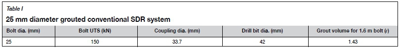
Sleeve couplings are also expensive. In the mainstream use of SDRs, the rods are typically 2-4 m long, so few couplings are needed to make up a drill string. However, in this project, the maximum length of the SDR segments was limited to 400 mm, so four couplings would be needed for a 1.6 m bolt.
An alternative type of SDR was sought. We found an unusual SDR rod manufactured in South Africa. Termed 'NCA steel' it is a 25 mm diameter drill steel with external rebar-type deformations. It had been manufactured on a small scale for specialized rehabilitation of concrete structures. The central flushing hole is only 11 mm in diameter, leaving a cross-sectional area of 396 mm2 - greater than that of the 20 mm conventional solid rockbolt. NCA steel had not been coupled previously. NCA steel has a minimum tensile strength of 940 MPa (Arcelor-Mittal, 2017). The high strength combined with the larger cross-sectional area allowed design of a taper-threaded internal coupling (see Figure 1). This avoided the hole diameter increase associated with conventional sleeve couplings.

Prototype NCA rods with the internal taper-threaded couplings were made up and tensile strength tests were conducted at a SANAS-accredited test facility. Minimum breaking load was 176 KN. This qualified the coupled NCA steel as being strong enough for the SDR component of the rockbolting system.
Drilling method - percussion or rotary?
Early in the project a decision had to be taken on the drilling method to use: percussion or rotary, as the choice was fundamental to the design and equipping of the rig as well as to configuration of the rockbolts/drill rods.
Compressive strengths (UCS) of hangingwail rocks in South Africa's gold and platinum mines are in the range of 120 MPa to over 250 MPa. Conventional production drilling in such rock is by percussion drills (Pickering and Ebner, 2001). There was limited data available on use of rotary drilling in hard rock. In 2003 one of the authors tested rotary drilling in the hangingwall at a platinum mine, using a hand-held bolter ('Turbo-bolter') and found that it was feasible.
Comparison of rotary and percussion drilling was carried out and the findings are summarized in Table II.
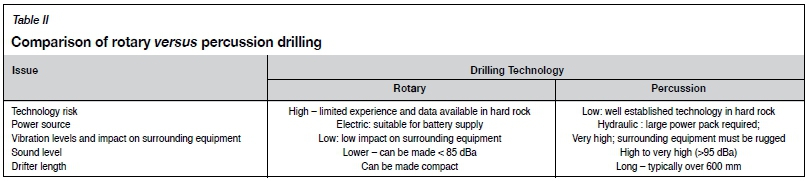
The comparison showed that rotary drilling was conceptually more suited to integration into the compact, low-height bolter rig but actual drilling capability and equipment specification were still unknown.
To confirm the feasibility of routine rotary drilling in hard rock and to gather data for equipment design, an instrumented drilling test rig was built (Figure 2).
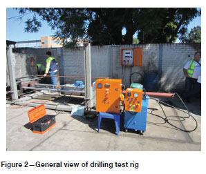
The test rig enabled drilling with controllable thrust and rotation speed, while measuring instantaneous penetration rate and torque. Norite (UCS 200 MPa) was used for the drilling trials.
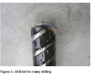
NCA drill rods were made up with shaped heads, into which tungsten carbide (TC) inserts were brazed (Figure 3). The TC inserts were 30 mm wide, resulting in holes with a diameter 5 mm greater than the 25 mm diameter NCA drill rods, for flushing of the drill chippings. Water was used for flushing.
Using the test rig, 56 holes were drilled between February and April 2013. This demonstrated that:
> Rotary drilling of norite with standard TC borers is feasible. Penetration rates exceeding 1.5 m/min were consistently achieved and the TC inserts lasted the required 1.6 m of drilling depth (Figure 4)
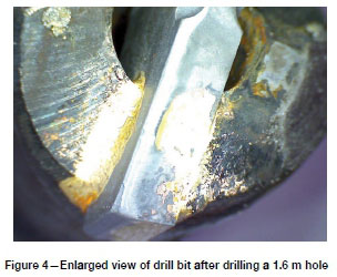
> The NCA steel and the internal taper-threaded couplings were successful as drill rods.
Extensive data on the penetration rate versus thrust and torque was obtained for design of the drilling head on the bolter and setting operating parameters. The best results were obtained at high rotation speed (700 r/min) and thrust in the range 4050 kN (O'Connor, 2013). A bilinear regression calculation on drill penetration rate versus rotation speed and thrust in the ranges tested gave:
Penetration rate (mm/min) = 1.29 r/min + 4.44 thrust (kN)
In 2018 a further series of drilling tests was carried out using an actual bolter, drilling into a large block of norite set up in a surface workshop. The results are reported in Appendix I.
Grouting of the self-drilling rockbolts
The user requirement of short hole-to-hole cycle time required a fast-setting grout. The bolter rig needed to move on to the following hole within seconds of completing an installation and the grout had to build strength rapidly to provide effective support. Speed had to be balanced with a working time long enough for the grout to be pumped through the bolt and fill the hole before setting.
Conventional bolted stope support uses resin capsules with a 30 second or 60 second setting time (Maepa and Zvarivadza, 2017) and these times formed the benchmark for performance of the pumped grout system. At the time of development (20122104) there were no cement grouts available that met these requirements. A two-component resin grout had been developed (Richter, 2005) for use with SDRs and we decided to test this material. The resin grout is an organo-silicate system, supplied as two liquids with viscosities in the range 150-300 mPa.s (Minova Carbotech, 2017). When the two components are vigorously mixed, a two-stage chemical reaction takes place. In the first stage, the mixture thickens and becomes thixotropic, but is still pumpable. This prevents the material from flowing out of the hole and ensures that the annulus around the bolt is completely filled. In the second stage, polymerization of the organic phase and precipitation of solid silica take place, resulting in a solid grout.
The resin grout first used had an initial hardening time {i.e. the time at which the bolter rig could release the bolt) of 60 seconds and reached full strength in 6 hours. Discussions with the manufacturer prompted further development and these times have now been shortened to 20 seconds and 60 minutes respectively. Variants of the same resin grout are being used in automated rockbolting developments elsewhere in the world (Bray and Johnsson, 2019).
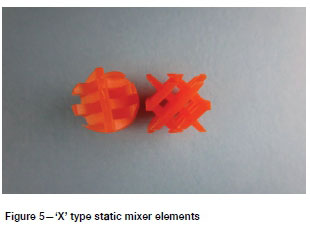
The fast reaction time of the resin requires near in-situ mixing. For this, single-use static mixers are incorporated into the base of each bolt. Workshop trials carried out to determine the length of static mixer required to produce complete mixing showed that an 'X' type static mixer 100 mm in length was adequate (Figure 5).
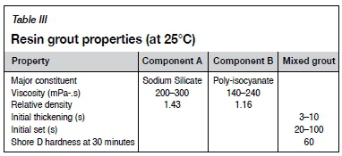
The properties and performance of the resin grout used in 2018 are shown in Table III.
Testing and qualification
Field short encapsulation pull testing
Individual segments of the SDRs were installed in 250 mm deep holes drilled in the hangingwall at a platinum mine near Rustenburg in July 2015. The holes were 30 mm diameter and were pre-drilled using a conventional roofbolter. After installation, the bolts were pulled with a hand-operated hydraulic ram at different times after installation. The results are shown in Table IV.
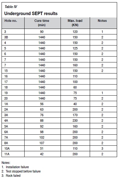
Salient outcomes from the tests were: > There were many aspects of the installation and testing process that had to be learned and mastered before consistent results were achieved
> Both the resin bond and the bolts themselves achieved the design loads.
Proof-of-concept trials, 2015
The complete rockbolting system was subjected to a proof-of-concept (POC) trial at the same platinum mine. After the initial development of operating procedures, measurements were made of cycle times. A typical cycle is shown in Table V.
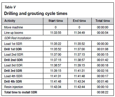
The POC trial showed that the ULP bolting system was able to achieve close to the user specification of installing one SDR in 8 minutes or less.
Excluding downtime and externally-caused delays the drilling times achieved were between 06:49 and 07:22 minutes.
Current status
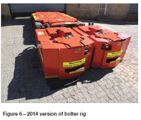
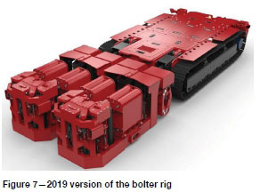
The system has been in use at a platinum mine on the eastern limb of the Bushveld Complex since 2017. Since 2015 the bolter rig has undergone significant evolution on the basis of operational experience. Figure 6 and 7 show the 2014 and 2019 versions respectively - the later version is more compact, lighter, and provides easier access for maintenance. The two drilling booms each incorporate staking rods that stabilize the booms during drilling, ensuring consistent alignment between the SDR segments and between the base of the drill string and the drilling head/resin injection ports.
As mentioned previously, the rockbolter is part of an equipment suite. The stope layout was re-designed for compatibility with the strengths and limitations of the equipment suite. The bolter is steered manually (using radio remote control) when moving between stope panels. The layout avoids the need to cross obstructions such as gullies.
Conclusions
A multi-year development programme involving users and equipment suppliers has resulted in a working system for automated and remote-controlled rockbolting in hard-rock mines with tabular stopes less than 1 m high. The cycle times already achieved and the removal of the operators from the immediate vicinity of the operation have the potential to bring about improvements in the productivity and safety of existing operations, mainly located in South Africa. In the longer term, the suite of ultra-low-profile mining equipment may allow some narrow orebodies, currently considered as uneconomic to mine, to be re-classified as mineral reserves.
References
Areclor-mittal. 2017. Material test certificates. Vereeniging, South Africa. [ Links ]
Bray, P. and Johnsson, A. 2019. Case study: LKAB Malmberget, self-drilling anchors and pumpable resin. Proceedings of DeepMine 2019. Southern African Institute of Mining and Metallurgy, Johannesburg [ Links ]
Harper, G.S. 2008. Nederburg miner. Proceedings of the Narrow Vein and Reef Symposium. Southern African Institute of Mining and Metallurgy, Johannesburg. pp. 2-4. [ Links ]
Joughin, N.C. 1976. Potential for the mechanization of stoping in gold mines. Journal of the South African Institute of Mining and Metallurgy, vol. 76, no. 1. https://www.saimm.co.za/journal/v076n06p285.pdf [ Links ]
Lynch, M. and White, B. 2013. Brave new world of autonomous mining systems. Proceedings of the World Gold Conference, Brisbane. Australasian Institute of Mining and Metallurgy, Melbourne. pp. 157-166. [ Links ]
Maepa, T. and zvarivadza, T. 2017. Installation of resin-grouted rockbolts in hard- rock mining: Challenges and solutions for improved safety. Journal of the Southern African Institute of Mining and Metallurgy, vol. 117, no. 4. pp. 329-336. https://www.saimm.co.za/journal/v117n04p329.pdf [ Links ]
Makusha, G. 2015. Personal communication. [ Links ]
Minova-Mai. 2017. Self-drilling systems product catalogue. Feistritz/Drau, Austria. pp. 3-10, 16. [ Links ]
Minova Carbotech. 2017. Carbothix 150709 technical data sheet. Essen Germany. [ Links ]
O'connor, D. 2014. Effect of atmospheric pressure on resin capsule rigidity. Proceedings of the SANIRE Coalfields Branch Symposium, November 2014. South African National Institute of Rock Engineering [ Links ]
O'connor, D. 2013. Interim report on rotary drilling trials in norite. Minova Africa (Pty) Ltd, Johannesburg. [ Links ]
Pickering, R. and Ebner, B. 2001. Hard rock cutting and development of a continuous mining machine for narrow platinum reefs. Proceedings of the 6th International Symposium on Mine Mechanisation and Automation. Southern african institute of mining and metallurgy, Johannesburg. https://www.saimm.co.za/journal/v102n01p019.pdf . [ Links ]
Richter, A. 2005. A method for embedding rock anchors. Australian patent application 2005297473 b2, 2005. [ Links ]
Rsc Ekusasa. 2007. Product datasheet. Rsc Ekusasa Mining, Johannesburg. [ Links ]
 Correspondence:
D.M. O'Connor
donald.oconnor@minovaglobal.com
Received: 29 Jul. 2019
Revised: 28 Nov. 2019
Accepted: 29 Nov. 2019
Published: January 2020
Appendix I
Second series of rotary drilling trials
In December 2018 a second programme of rotary drilling trials was carried out as part of ongoing system improvement. This programme used an actual bolter to carry out the drilling; the results could therefore be applied directly to optimize drilling parameters and practice.
The holes were drilled into a large block of quarried norite, supported on a frame to simulate the hangingwall of a stope (Figure I-1)
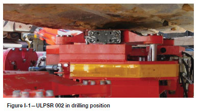
Two series of tests were carried out, one with 'soft collaring' of the bit and one without. Soft collaring used a slow approach of the bit to the rock face and a gradual ramp-up of thrust and rotation speed. It was intended to reduce the likelihood of the bit shattering on contact with the rock.
The tests measured drilling time against rotation speed at different thrust settings. Drill bit condition was recorded after each hole.
The results are summarized in Figures I-2 and I-3.
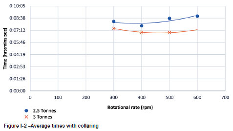
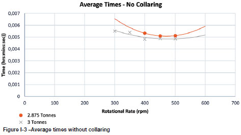
Findings
> Increasing thrust force results in a reduction in drilling time, but when thrust exceeded 3 t (30 kN) there was a heightened risk of premature bit failure.
> For each thrust setting, there was an indication of an optimal rotation speed. When the rotation speed exceeded 600 r/min there was heightened risk of premature bit failure.
> There was no significant difference in time when drilling with soft collaring and not using soft collaring.
> The drill bits were capable of drilling at least 1.6 m in the hard norite, provided that the thrust was limited to 3 t (30 kN) and the rotation speed less than 600 r/min. ♦

