


Services on Demand
Article
 English (pdf)
 Article in xml format
 Article references
Indicators

Related links
-
 Cited by Google
 -
 Similars in Google
Share

 Permalink
Journal of the Southern African Institute of Mining and Metallurgy
On-line version ISSN 2411-9717
Print version ISSN 2225-6253
J. S. Afr. Inst. Min. Metall. vol.120 n.1 Johannesburg Jan. 2020
http://dx.doi.org/10.17159/2411-9717/854/2020
DEEP MINING PAPERS
The geotechnical evolution of deep-level mechanized destress mining at South Deep mine
P.G. AndrewsI; R.J. ButcherI; J. EkkerdII
IGold Fields, Australia
IIGold Fields, South Africa
SYNOPSIS
The South Deep mine is a deep-level mine that is actively mining between 2600 m and 3000 m below surface, with expectations to mine to 3400 m depth. The The orebody lends itself to a fully mechanized mining method.
The main geotechnical challenges for successfully mining the South Deep orebody were to destress and then cost-effectively extract the massive, low-grade orebody. Since Gold Fields acquired South Deep in 2007, several mining methods have been used to date, but destressing was done conventionally using traditional South African narrow-reef gold mining methods. In 2015, the mine moved to high-profile (5.5 m high) horizontal destress development with mechanized installation of ground support, and crush pillars were replaced with yield pillars. This has resulted in a safer working environment with industry best-practice support standards and less seismic energy release, while still allowing appropriate productivity rates
This paper outlines the geotechnical processes used to overcome issues as they were encountered, including ground support, seismicity, and rock mass conditions, and highlights the key leanings of a deep-level massive mine's evolution over time.
Keywords: mechanized mining, destress development, ground support, yield pillars, seismicity, backfill.
Introduction
South Deep gold mine is situated approximately 45 km southwest of Johannesburg and 20 km south of Randfontein in the Far West Rand goldfield of the Witwatersrand Basin. The mining area covers 3563 ha and extends for 9.5 km north-south and 4.5 km east-west at its widest points.
Geology
The geology at South Deep was described by Watson et al. (2014). The orebody lies within the Central Rand Group of the Witwatersrand Supergroup and is overlain by the Ventersdorp lavas (see Figure 1). The Ventersdorp Contact Reef (VCR) and Upper Elsburg reefs are the most economically important units.
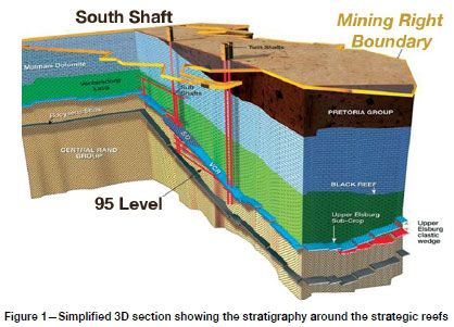
The Upper Elsburg reefs suboutcrop against the base of the VCR, which is a major stratigraphic unconformity. Towards the east, the orebody diverges and thickens up to about 120 m at the eastern extremity of the mine boundary, with an increasing percentage of non-profitable quartzite middlings in the thicker regions (see Figure 2). The targeted reef packages within the sequence are the EC and MB reefs. The dip and strike of the orebody varies across the mine, but it generally dips to the south at between 10° and 14°. This dip angle is too steep for normal mechanized equipment due to excessive loading on braking components.
The orebody is currently being mined at depths of between 2600 m and 3000 m, and future mining is planned at 3400 m below surface. The virgin vertical stress is high and will become higher as the depth increases.
Mining
Over the years, several different mining methods have been used at South Deep to maximize extraction of the large orebody, while trying to ensure that these are the safest and most cost-effective methods available. Since Gold Fields acquired the mine in 2007, several methods have been trialled and abandoned. This optimization work has been an ongoing process as the level of knowledge and confidence in each of the methods increased.
The underlying principle of all methods is that a narrow tabular cut is mined first. This destresses the orebody directly above and below the cut, ensuring the safest and most cost-effective extraction of the orebody.
The destressing philosophy will be discussed first, followed by a description of the various mining methods used by Gold Fields for the extraction of the destress mining layouts. Extraction sequences for the massive mining will then be discussed. Backfill plays an integral role in all the methods, and the backfill practices for each method are discussed.
Geotechnical environment
Rock mass conditions
Most of the conglomerate units within the Upper Elsburg package are extremely strong, brittle rocks. SRK (2006) identified three rock strength classes within the Upper Elsburg sequence.
> Argillaceous and gritty quartzites are the lower strength parts of the package, although they are still generally strong, with ocranging from 80 to 150 MPa.
> Medium-strength, sub-argillaceous to siliceous quartzites with σcranging from approximately 150 to 200 MPa.
> High-strength siliceous conglomerates and quartzites with σc> 200 MPa.
The RMR within the reef package is variable but generally high, with many RMR values over 80. Based on geotechnical logging and mapping, the geological strength index (GSI) ranges from 55 to 75.
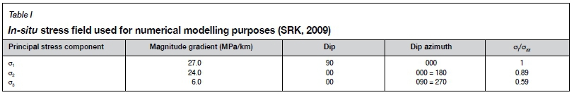
Stress field
The virgin stress tensor used in the modelling was determined from stress measurements using CSIR cells, carried out at a depth of 2650 m below surface. SRK (2009) provides the in-situ stress field as summarized in Table I.
Destress philosophy
In high-stress environments, the rocks of the Upper Elsburg package store strain energy that can be released violently in the form of rockbursts. The solution was to mine a narrow tabular cut, which would destress the orebody above and below to allow normal massive mining techniques to be conducted (James, MacDonald, and Raffield, 1998). Initially, conventional destress cut mining was used at South Deep as this method is used extensively at depth in South Africa.
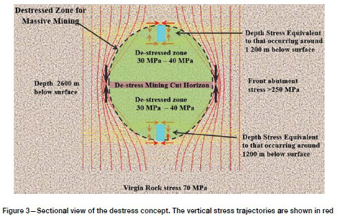
Early elastic numerical modelling work indicated that an optimum conventional destressing cut could be achieved with a stoping width of 1.5 m to 2.0 m and backfilling. To ensure that the average energy release rates (ERR) were maintained below the mining-industry accepted average criterion of 30 MJ/m2 (Jager and Ryder, 1999), the panels in the destress cut were limited to 250 m, separated by 60 m wide stability pillars. Later modelling showed that the vertical stress could be reduced to approximately 30 MPa to 40 MPa up to 60 m above and below the destress cut (see Figure 3). The destress envelope that was created had stresses one would expect at a depth of 1 200 m.
Backfill is therefore the most crucial support element. The destress cuts had to be backfilled to limit bedding separation in the hangingwall and provide areal support and energy absorption capacity.
Although mining the destress cuts conventionally worked well, the rate of destress advance was slow and did not open up enough of the mining areas to achieve the required production rates for longhole stoping.
Mechanized destress mining history
Mechanized apparent dip destress mining
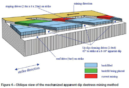
The use of the mechanized apparent dip destress method started in 2008. This was the first mechanized destress method implemented and it involved mining a combination of apparent dip drives to excavate the target destress cut horizon in the plane of the reef (see Figure 4). Development was 2 m high and 4 m wide. The concept was to mimic conventional destressing using mechanized equipment.
Ground support systems
Hangingwall support initially comprised 46 mm diameter friction bolts and 5.6 mm gauge weldmesh. Friction bolts were phased out and replaced by more robust flexi-anchors as an interim measure. It was planned to eventually replace the anchors with yielding reinforcement to provide the necessary energy absorption requirements.
Once the stoping drives were completed, they were backfilled with cemented classified tailings (CCT). There was no need to construct a backfill paddock as the bulkheads were formed using POWERITE™ bags filled with CCT. Backfill was contained by the two bulkheads, previously placed backfill, and the rock face.
Seismicity
The ERR associated with this layout are equivalent to those of conventional mining with the same regional pillar configuration. In principle, the destressing effect was presumed to be identical to that achieved with conventional destressing. Larger events clustered around geological structures and stabilization pillars, while smaller events (ML 0.0 to ML 2.0) were concentrated around the destress mining front.
Issues and method change
Apparent dip mechanized mining of the destress slots was discontinued in late 2008. Issues with the method included:
> Difficulty in maintaining development on the correct ore horizon, especially when encountering faults
> Delays in backfill and difficulties in getting a tight fill against the hangingwall with bags
> Ground support was still installed conventionally, as mechanized bolting was not viable due to the narrow mining heights. There was very little synergy with massive mining, and no shared development.
Low-profile mechanized destress mining (horizontal destress)
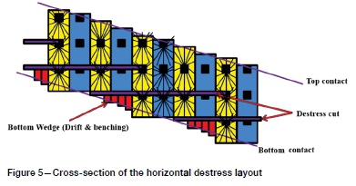
The horizontal destress method with no pillars was used from 2009 to 2012. This method involved mining layered horizontal destress cuts. These horizontal cuts overlap and destress the target mining horizons (see Figure 5). Access to the destress cut was via a spiral decline located beneath a previously mined area and which was always destressed. Access drives were developed horizontally from the spiral decline to each horizontal destress horizon. The mining corridor width of 240 m between stability pillars was maintained. There was a 17 m vertical spacing between destress cuts.
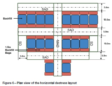
Each horizontal cut was mined as a series of perpendicular drives, which used set leads and lags to mitigate potential rockburst and stress damage. All development was planned at 5.0 m wide and 2.2 m high (Figure 6). Main access drives (MADs) were developed in the dip direction (Watson et al., 2014). Stoping drives (SDs) were mined adjacent to the MADs on a modified drift-and-fill sequence. Strike access drives (SADs) were created on strike every 10 m by placing backfill in the SDs. This ensured that cross-fracturing in the SAD hangingwall was avoided. The plan was to integrate this destress cut and subsequent longhole stoping by utilizing the original destress cut drives. These drives would be filled after the destress cut was completed. Redeveloping through the fill was required with backs stripping or footwall slipping being undertaken to create the final dimensions of the longhole stoping access drives, designed to be at least 5.0 m high by 4.5 m wide.
This mechanized horizontal destress method had several perceived advantages over the apparent dip destress method (Joughin, Bester, and du Plooy, 2011), including:
> Development layout synergies with the subsequent massive mining
> The ramp infrastructure can be utilized for massive mining
> The destress cut access and strike drives could be utilized for subsequent longhole stoping
> Higher grade ore from destressing development
> Adjustments to the layout are not required to accommodate geological structures, as would be the case with an apparent dip layout
> Having the destress within the trackless target horizon maximizes the destress envelope
> Multiple longhole stopes can be stacked on top of each other to form one large stope.
Ground support systems
Ground support continued to use the 46 mm diameter friction bolts and 5.6 mm gauge weldmesh in the development in existing destress shadows. Destress development into higher stress abutments used the Flexibolt, a yielding anchor from M&J Mining. Dynamic yield was achieved by dragging 300 mm of cable, located at the back of the anchor, through a small orifice at the position of the anchor. However, yielding bolts were still installed and tensioned conventionally.
Ground performance
Overall, rock mass conditions post-extraction were considered fair. If backfill was placed on time and installed tight against the hangingwall, then hangingwall conditions were good. Often, backfill was installed late or not installed tight against the hangingwall. This caused the hangingwall conditions to deteriorate, with opening along bedding planes and large-scale convergence up to about 500 mm.
Production
The horizontal destress method was used from 2009 to 2012. Production was approximately 1.4 Mt in 2009, 1.75 Mt in 2010, and 1.98 Mt in 2011. During these years about 56% of total tonnage came from development (destress, normal, and new mine development) and 44% from some form of stoping (longhole, or drifting and benching). The large amount of development was to set up stoping areas in the future.
Seismicity
Seismic activity averaged around 40 events > ML 0.0 per month. Larger events clustered around pillars, while smaller events (ML 1.0 to ML 2.0) were concentrated around the destress mining front. There was a moderate correlation between the number of events per month and production. The monthly seismic energy released was between 5 MJ and 180 MJ, with the average being about 45 MJ/month.
Issues and method change
The mechanized horizontal destress method was used between 2009 and 2011. During this time, several issues were noted with the method, including:
> Difficulty in maintaining 90° turnouts on the destress horizon. Turnouts became large and required more backfill bags to reduce spans
> Difficulties mining on-line and on-grade
> Delays in backfill placement, which caused delays in development and future stoping
> Difficulties when tight-filling to the backs with backfill bags
> Convergence in the centre of the destress cuts (approx. 500 mm). This was exacerbated by backfilling delays
> Bags provided support only when closure occurred.
Due to issues with backfilling delays and convergence, the method was changed to a horizontal destress method with crush pillars. Trials of the method began in 2012 and it was fully adopted in 2013.
Low-profile mechanized destress mining with crush pillars (LPS)
This method involved the addition of crush pillars in the horizontal destress cuts. The crush pillar concept incorporates pillars intended to crush while they are still part of the face, but which have sufficient residual strength to provide the required support resistance to the immediate hangingwall, both at the face and in the back areas. These pillars can yield over a large deformation range at their residual strength level (Ozbay, Jager, and Ryder, 1995).
The LPS method was utilized for three years from 2012 to 2014. Access to the destress cut was still obtained via a spiral decline, and access drives still developed horizontally from the spiral decline to each horizontal destress horizon. The mining corridor width was maintained at 240 m between stability pillars with 17 m vertical spacing between destress cuts.
There were many expected advantages from the transition to LPS, as documented by Watson et al. (2014). These included:
> Less backfill required
> More heading availability
> The crush pillars are an active support system and would inhibit hangingwall unravelling, which is often observed where the reef is replaced by backfill.
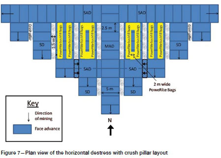
The destress development still used the 5.0 m wide and 2.2 m high design. Main access drives were first developed in the dip direction (see Figure 7). SDs were then mined adjacent to the MADs in a staggered configuration to maintain acceptable lead-lag distances. This distance was originally designed to create a 1.5 m wide crush pillar, but was expanded to a 2.0 m wide crush pillar. Stope access drives (SADs) were developed at 15 m spacing by cutting 5 m holings through the crush pillars at the appropriate locations. PoweRite™ backfill bags were installed along the edges of the crush pillars to confine the pillars and reduce pillar disintegration at large closures.
Ground support systems
Ground support in the destressed rock mass used the 46 mm diameter friction bolts and 5.6 mm gauge weldmesh in the development. The sidewalls of the MAD were also supported with friction bolts and weldmesh. The hangingwall of the destress development into higher stress abutments was supported with 5.6 mm diameter weldmesh and yielding tendons. Yielding bolts continued to be installed and tensioned conventionally. Many of the Flexibolts could not be installed properly as correct tensioning of the bolts could not be undertaken. This allowed bolts to loosen and slip, causing further dilation of the hangingwall.
Ground performance
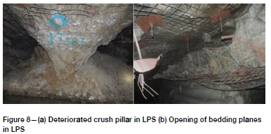
Rock mass conditions within the destress cut post-extraction were considered poor. Crush pillars deteriorated quicker than expected and provided very little post-peak load capacity (see Figure 8a). Late placement of backfill saw hangingwall deterioration with large openings in bedding planes occurring (Figure 8b). Convergence was high, with closure greater than 500 mm in many of the destress cuts.
Production
The first two years' production was very good, with over 2.05 Mt extracted in 2012 and 2.24 Mt in 2013. However, due to poor ground conditions and the required remediation, there was a significant decrease in tonnage in 2014 with only 1.09 Mt extracted. During these years, some 60% of the total tonnage came from development and 40% from stoping.
As can be seen from the production results, the reduction in the need for backfill saw a significant increase in extraction rates for two years. Backfill fell further behind requirements as significantly more bags to fill at more locations were required by the new method. This lack of backfill reduced pillar confinement, which allowed pillars to fret away causing large convergence within the destress cuts. The large levels of convergence prevented productive mining due to the extra rehabilitation and backfill requirements.
Seismicity
During 2012 and 2013, seismic activity averaged around 60 events > ML 0.0 per month. While mining with the LPS method, the number of events of magnitude Ml > 2.0 increased from a historical average of one per month to 1.8 per month. There was a moderate correlation between the number of events per month and production.
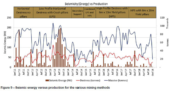
From January 2012 to March 2013, the monthly seismic energy released was between 5 MJ and 90 MJ, with the average being some 30 MJ/month. However, from April 2013 to January 2014 the monthly seismic energy released increased to between 40 MJ and 200 MJ, with the average being some 100 MJ/ month. The increase in the energy released and the number and magnitude of events is attributed to the high levels of convergence caused by the crush pillars over-crushing and losing all load-bearing capacity (see Figure 9).
Issues and method change
Several issues with the method were noted, including:
> Convergence in the centre of the destress cuts of about 500 mm as crush pillars deteriorated. This created very poor working conditions
> The convergence was accelerated by backfilling delays
> Difficulty in maintaining 90° turnouts on the destress horizon, as turnouts became large and required more backfill bags to reduce spans
> Difficulties mining on-line and on-grade
> Delays in backfilling, which caused delays in development and future stoping.
> Difficulties when tight-filling to the backs with backfill bags.
After the poor performance in early 2014, Gold Fields management instated a geotechnical review board to review and comment on the LPS mining method. The results of the review indicated that the LPS method was flawed owing to the issues noted above. The report outlined many short-term remediation strategies, including flood-filling certain areas to control convergence and a regime to catch up on the backlog of secondary support. These recommendations were adopted and impacted on the 2014 production figures.
The main recommendations for the medium to long term were to continue using the destress method but move to a larger development profile to ensure mechanized support installation. Pillars were to be larger but still designed to yield to prevent pillar bursts. An investigation to consider a reduction in the corridor spans to control convergence was also recommended.
High-profile mechanized destress mining with yield pillars (HPS)
During late 2014 and early 2015, much work was done on the recommendations provided by the geotechnical review board. Many areas were flood-filled based on rock mass conditions, and production was further impacted due to the work on the secondary support backlog.
The outcome of this work was the creation of the high-profile mechanized destress mining method with yield pillars (HPS). Further work was done on detailing the new method, followed by numerical modelling of these new designs.
Yield pillars are pillars which are intended to have a safety factor > 1 or even equal to unity when first formed, but then yield in a stable manner at stress levels near to peak strength (Ozbay, Jager, and Ryder, 1995). The pillars are sized, often using empirical and observational approaches, so that they do not store excessive strain energy and burst, but remain sufficiently intact to maintain a residual strength. In practice, yield pillars are intact when formed and are then weakened as the load on them increases beyond their load-bearing capacity, causing them to yield.
The new method involved the following changes.
> Increasing the destress development profile to 5.0 m high and 4.5 m wide to allow for mechanized support installation.
> Changing the crush pillars to yielding pillars. The original size of the pillars was to be 6 m wide by 10 m long, but this was changed to 8 m wide by 20 m long yielding pillars in 2017 (see Figure 10).
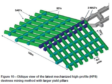
> Mechanized ground support changed to include dynamic support as primary support.
> Reduction of corridor spans to 180 m. This was based on numerical modelling results to ensure ERR were below industry requirements.
> The destress cut layout was changed to a herringbone configuration to reduce the number of both 90° turnouts and four-way intersections. The 17 m vertical spacing between destress cuts was maintained.
The method was trialled in early 2015. From mid-2015 to mid-2016, the mine used both LPS and the new HPS method. By mid-2016, all new destress cuts were mined as per the new design. In 2017, a modification to the design to incorporate a trial of 8 m wide by 20 m long yield pillars was undertaken. This new design also had twin MAD access and allowed for workshops on each destress level.
Ground support systems
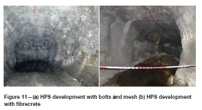
Ground support in the destressed rock mass used the Garock Hybrid™ dynamic friction bolt and 5.6 mm gauge weldmesh in the development. The support scheme was installed across the backs of the drive and down the sidewalls to 1.5 m from the floor at 1.4 χ 1.2 m spacing. Cable bolts were to be installed in intersections and at longhole stope brows. All ground support was mechanically installed. In 2018 shotcrete was added to the support scheme to reduce pillar unravelling below the mesh line.
Ground performance
The HPS method resulted in an immediate improvement in rock mass conditions during the development of the destress cut. Less convergence was observed, with a maximum of about 200 mm. Over the first 18 months of the HPS trial, it was observed that the 6 m wide by 10 m long pillars were yielding to the point of crushing. The highly fractured rock mass in the yield pillars was unravelling below the mesh line, causing the further reduction in pillar size. Rock mass conditions further improved with the larger pillars, which are in use today (see Figure 11a and Figure 11b).
Production
The production rate built up from the 2014 low of 1.09 Mt to 1.24 Mt, increasing again in 2016 to 1.72 Mt. The change to larger yield pillars in 2017 saw production remain consistent with 1.61 Mt extracted. During these years, some 55% of the total tons came from development.
Seismicity
Since the inception of the HPS method, monthly seismic energy released has been between 5 MJ and 60 MJ, with the average being < 20 MJ/month. The reduction in the energy released and the number and magnitude of events is attributed to the reduced levels of convergence. Larger events still cluster around stability pillars and on major structures, while smaller events (ML -1.0 to 2.0) are concentrated around the destress mining front.
Further details on seismicity at South Deep are given in the companion paper.
Conclusion
Over the years, South Deep mine has made considerable progress in developing a fully mechanized mining method to extract the extensive orebody both laterally and vertically. All methods have taken advantage of the destress philosophy, which incorporates a tabular mining cut within the target package to destress the rock mass above and below the cut.
Mining methods have changed over the years from a low-profile apparent dip destress method without pillars to a horizontal low-profile method, initially without pillars but subsequently using crush pillars as part of the sequence (LPS). Due to the inability to perform mechanized support installation and poor rock mass conditions associated with the LPS methods, a high-profile method with mechanized support installation and large yield pillars was adopted.
The latest HPS method creates a safer working environment with industry best-practice support standards and releases less seismic energy than the LPS methods, while still allowing appropriate production rates.
The South Deep rock engineering team has used an observational method to continually assess ground conditions, pillar stability, and development convergence to allow ongoing optimization and changes to each method, culminating in the current HPS method with large yield pillars.
Acknowledgements
The authors would like to acknowledge the South Deep management team for their assistance in writing this paper.
References
Jager, A.J. and Ryder, J.A. 1999. A handbook on rock engineering practice for tabular hard rock mines. Safety in Mines Research Advisory Committee (SIMRAC), Johannesburg. [ Links ]
James, J.V., MacDonald, A.J., and Raffield, M.P. 1998. The backfilling philosophy for massive mining at depth in the South Deep Section, Western Areas Gold Mine. Proceedings of the Sixth International Symposium on Mining with Backfill. [ Links ]
Bloss, M.L. (ed.). Australasian Institute of Mining and Metallurgy, Melbourne. [ Links ]
Joughin, W.C, Bester, W.M., and du Plooy, M. 2011. Mining methods and backfill at South Deep Gold Mine. Minefill 2011. Proceedings of the International Conference on Mining with Backfill. Southern African Institute of Mining and Metallurgy, Johannesburg. [ Links ]
Ozbay, M.U., Jager, A.J., and Ryder, J.A. 1995. The design of pillar systems as practised in shallow hard-rock tabular mines in South Africa. Journal of the South African Institute of Mining and Metallurgy, vol. 95, no. 1. pp. 7-18. [ Links ]
SRK. 2006. South Deep regional pillar optimization study (Stage II). Report 352262/2 to South Deep. February 2006. [ Links ]
SRK. 2009. Rock engineering assessment of proposed horizontal destress cuts and massive mining at South Deep. Report 396956/1 to South Deep. February 2009. [ Links ]
Watson, B.P., Pretorius, W., Mpunzi, P., du Plooy, M., Matthysen, K., and Kujpers, J.S. 2014. Design and positive financial impact of crush pillars on mechanized deep-level mining at South Deep gold mine. Journal of the Southern African Institute of Mining and Metallurgy, vol. 114, no. 10.. pp. 863-873. [ Links ] ♦
 Correspondence:
P.G. Andrews
peter.andrews@goldfields.com
Received: 29 Jul. 2019
Accepted: 6 Sep. 2019
Published: January 2020

