


Services on Demand
Article
 English (pdf)
 Article in xml format
 Article references
Indicators

Related links
-
 Cited by Google
 -
 Similars in Google
Share

 Permalink
Journal of the Southern African Institute of Mining and Metallurgy
On-line version ISSN 2411-9717
Print version ISSN 2225-6253
J. S. Afr. Inst. Min. Metall. vol.120 n.1 Johannesburg Jan. 2020
http://dx.doi.org/10.17159/2411-9717/839/2020
DEEP MINING PAPERS
Full-scale rockbolt testing in the laboratory: Analysis of recent results
S.A. HagenI; T. LarsenI; A. BerghorstII; G. KnoxIII
ISINTEF AS, Trondheim, Norway, Canada
IINew Concept Mining Canada, Saskatoon, Canada
IIINew Concept Mining, South Africa
SYNOPSIS
Rockbolting is a method used for rock reinforcement in underground mining and tunnelling. There is a large variety of different types of rockbolts with different support functions. The behaviour of a rockbolt in a rock mass depends on the function and material of the bolt itself, combined with the mechanical properties of the rock mass, deformation capacity, strength, and level of stress. Testing of rockbolts in full-scale laboratory-controlled conditions is therefore of great importance. At the rock mechanics laboratory of SINTEF and the Norwegian University of Science and Technology (NTNU) in Trondheim, a rockbolt test rig has been developed for full-scale testing for pull, shear, and combination pull-shear tests. In this paper we describe the principles behind this quasi-static full-scale testing and include the results and analyses of recent tests on different types of rockbolt. The applicability of the test rig for rockbolt selection and rock support design is also discussed.
Keywords: laboratory testing, rock support, rock mechanics, rockbolting.
Introduction
At the rock mechanics laboratory of SINTEF and NTNU in Trondheim (Norway), a rockbolt test rig has been developed for full-scale testing for pull, shear, and combination pull-shear tests. The test rig was developed in 1995 in conjunction with Gisle Stjern's doctoral thesis. The test rig was financed by research funds and also by 0rsta AS, one of the leading suppliers of rockbolts. The purpose of Stjern's work was to investigate the mechanical performance of different rockbolts under different loading conditions, with the aim of simplifying the choice of bolt type and design for a given application (Stjern, 1995). Subsequently, the bolt test rig has been used for several master's and doctoral research projects as well as for commissioned test work. More than 35 different bolt types have been tested in the full-scale rig. The rock mechanics laboratory at SINTEF/NTNU has gained valuable experience and significant knowledge as a result of these test programmes.
An important element of this test facility is that it allows us, in a controlled and fully monitored way, to pull/shear the bolts to loads beyond their capacity. This includes testing the capacity of the fixation system using fully-grouted/resin-grouted bolts or other methods. Thus, it can also be used as a system test.
SINTEF was commissioned by New Concept Mining (NCM) to test various types of bolts in the rock mechanics laboratory. The purpose of the tests, which ran from 2016 to 2018, was to certify the bolts for use in specific mines and also certify their properties. Some of the results from these tests are presented as examples from the full-scale rockbolt test rig, and compared to standardized tests performed elsewhere on the same bolts.
Test arrangement
The SINTEF/NTNU rockbolt test rig
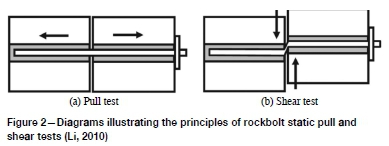
The SINTEF/NTNU rockbolt test rig consists of a rigid frame enclosing two cubic concrete blocks (see Figures 1 and 2). The two concrete blocks can be moved relative to each other in two different directions in the horizontal plane to simulate shear and tensile loads on the test bolts as shown in Figure 2. Each block measures 0.95 m along each side. To simulate hard rock conditions and secure strong fixation points, both blocks are cast from high-strength concrete (UCS approx. 120 MPa). The blocks are cured for at least 28 days after casting and before testing. The test rig has a loading capacity of 600 kN in tension and 500 kN in shear. The hydraulic loading system consists of two hollow 300 kN jacks pulling the tensile cube, and one ram jack pushing the shear cube. The hydraulic pressure cylinders have a maximum stroke length of 250 mm in tension and 150 mm in shear.
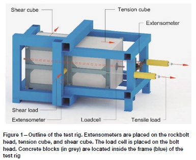
Roller bearings are installed between the blocks and the frame in order to guide the blocks and minimize frictional resistance. The roller bearings and frame also minimize rotation of the concrete blocks during the test. The test rig is instrumented with extensometers, load cells, and hydraulic pressure transducers. The data from these is used to generate the load-deformation characteristics of each test. The practical accuracy of the readout is 1 kN in load and 1 mm in deformation. Strain gauge measurement can be used to obtain detailed information of the load distribution along the bolt during the test.
This test will be referred to as the SINTEF/NTNU shear or pull test in the following sections.
Test procedure
Drilling holes for bolt installation
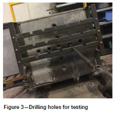
Before the cured blocks are installed in the test rig, the rockbolt test installation boreholes are drilled to the same diameter as used in the field. Figure 3 shows percussive drilling of the test boreholes. It is important that the boreholes are correctly aligned in the concrete blocks, especially for correct installation of the rockbolts. Each pair of blocks can accommodate a maximum of 13 tests before the boreholes approach too close to the edge of the block for accurate testing. Holes that are near the edge of the block can only be used for pull tests to avoid failure of blocks. The hole diameter can be adjusted to the specifications of the rockbolt being tested. Typical diameters are 33 mm and 48 mm. The rockbolt length that can be accommodated is approximately 1.8-2.0 m to suit the geometry of the test rig and depending on the bolt type.
Installing the rockbolts
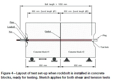
Figure 4 shows the principles for installing rockbolts in the concrete blocks. To simulate in-situ conditions, the SINTEF/ NTNU procedure requires that the bolts are tested with the same outfit as for normal installation. The two concrete blocks are placed into the frame and the alignment of the drill-holes for the specific test are checked. A hollow rubber gasket (8 mm thick, 150 mm diameter) is placed directly over the drill-hole, creating a seal when the two concrete blocks are pressed together. The seal prevents cement mortar or resin from flowing between the concrete blocks, as well as creating a gap of approximately 5 mm between the concrete blocks. This gap minimizes the influence of the joint shear resistance during a shear test. A constant load of 15-20 kN compresses the concrete blocks during the installation of the rockbolt and the curing of the cement mortar or resin. Mixing and filling with grout is normally performed with ordinary field equipment. The drill-hole needs to be plugged at the far end and grouting is performed carefully to ensure complete filling. Curing time and water-cement ratios are important factors regarding the installation and are carefully documented. As standard for cement mortar, a curing time of a minimum of 72 hours and a water-cement ratio of 0.32 are used. Other types of bolt anchoring can also be applied, such as mechanical anchoring and friction anchoring.
Testing of bolt performance
When the installation is complete, the testing will normally commence after 72 hours and the clamping force of 15-20 kN is then removed. The rockbolt head is equipped with a load cell to measure the load transferred to the head of the bolt in the test. The nut of the bolt head is normally pretensioned to a tensile load of 5 kN to ensure good contact. Extensometers are mounted on the bolt and the concrete blocks to measure displacement. Before the test is conducted, the test rig hydraulic cylinders are pressurized to a 15 kN load in the test direction (shear or pull) to remove any slack in the system. Testing is then conducted at a constant deformation rate of approximately 30 mm/min until failure. The data-logging rate is 5 Hz during the whole test. After testing, the failure mode of the bolt and bolt head is carefully inspected and documented with photographs and comments.
Test results
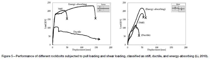
Test results include yield load, ultimate load, and deformation. The results are reported in tabular form with graphs and photographs from the test. Shear capacity of bolts is shown as applied shear load, including the shear resistance of the joint. Comments describe the type of failure and other factors that could be of importance for the test results. Documented bolt performance is based on a minimum of three individual test runs for both shear and pull tests. Rockbolt behaviour can be classified as stiff, ductile, and energy-absorbing from the point of view of bolt performance (Li, 2010). Figure 5 shows typical test result graphs from the SINTEF/NTNU test rig for three different bolts subjected to shear and pull tests.
Test apparatus - Direct shear and tensile test
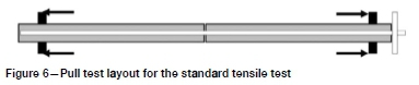
Both the direct shear test and pull test as described below are common industry testing methods. However, special tools and jigs were designed by NCM for conducting their own tests. The tests were commissioned and performed at reputable testing centres, including the CSIR in Johannesburg. The purpose of these tests was to attempt to quantify the performance of the rockbolts. The pull test results were obtained by testing an entire rockbolt grouted inside a steel tube which is cut at its mid-point. The assembly is fitted into a tensile testing machine and pulled until the rockbolt breaks. The layout of the pull test is shown in Figure 6. The data from these tests is presented in the following section. The results from the SINTEF/NTNU testing machine will be compared to the results obtained from some of these shear and pull tests.
The standard shear test involves grouting a portion of a rockbolt in a steel tube which is cut in two places around its midpoint. This assembly is then fitted into a double shear testing jig as indicated in Figure 7.
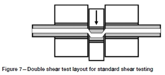
The double shear test induces a shear failure in two positions on the test sample, and therefore in order to quantify the single shear performance of the rockbolt, the load is halved. During this test the loading head travels at approximately 30 mm/min. The test is designed so that the two outer components are supported while the middle portion moves downward. This test induces a double shearing action on the test sample. It should be noted that during this test the loaded sample is confined within the test jig.
These tests will be referred to as the standard shear or pull test in the following sections.
Recent test results
Results from recent tests undertaken at SINTEF/NTNU include data for the PAR1 and Hydrabolt manufactured by NCM. The results from the SINTEF/NTNU testing machine will be compared to the results obtained from standard pull and shear tests described above on the same bolt types.
Pull test: grout-anchored energy-absorbing rockbolt -PARI 20 mm bolt
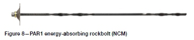
The PAR1 bolt (Figure 8) is an energy-absorbing rockbolt designed with a paddled yielding bar. This yielding bolt is designed for use in underground mines that experience squeezing ground and/or rockbursting. The design of the PAR1 bolt is such that it can be used with a variety of encapsulated media, including cementitious grout and resin capsules. Installation was completed as per the abovementioned test procedure in 33 mm test holes drilled in the concrete blocks. The rockbolts were fully grouted with an NCM grout designed for use with rockbolts in high-temperature mines. Testing was carried out after a minimum curing time of 48 hours.
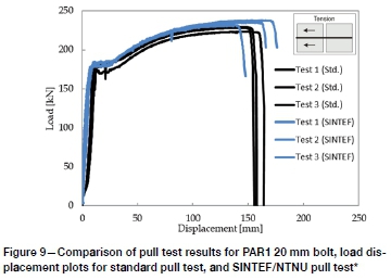
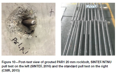
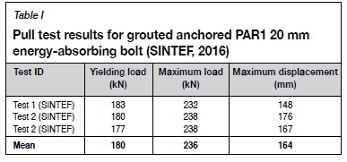
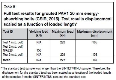
Tables I and II show pull test results for the two different methods, and load-displacement behaviours of the bolts are shown in Figure 9. For the SINTEF/NTNU pull test, the mean maximum load and displacement are 236 kN and 164 mm respectively. For the standard pull test, the mean maximum load and displacement are 227 kN and 160 mm respectively. Figure 10 shows the failed bolts.
Shear test: grouted energy-absorbing rockbolt - PARI 25 mm bolt
This test was performed using a PAR1 25 mm bolt (see Figure 8). The PAR1 25 mm bolts that were submitted for shear testing are manufactured from high strain-to-failure steel. These rockbolts are drawn from a single batch of steel from a standard production line with no special treatment during manufacturing. Installation was completed as per the abovementioned test procedure in 33 mm test holes drilled in the concrete blocks. The rockbolts were fully grouted with an NCM grout designed for use with rockbolts in hot mines. Testing was carried out after a minimum curing time of 48 hours.
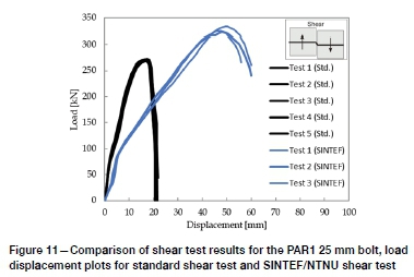
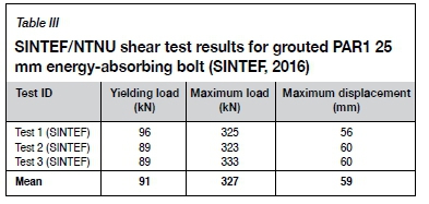
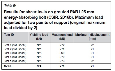
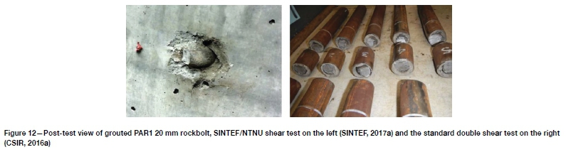
Tables III and IV show shear test results for the two different methods; load-displacement behaviours of the bolts are shown in Figure 11. For the SINTEF/NTNU shear test, the mean maximum load and displacement are 327 kN and 59 mm respectively. For the direct shear test the mean maximum load and displacement are 271 kN and 21 mm respectively. Figure 12 shows the failed bolts.
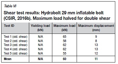
Shear test: inflatable bolt - Hydrabolt 29 mm
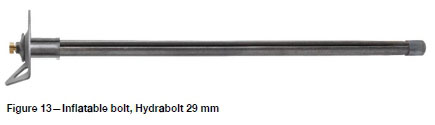
Figure 13 shows the 29 mm Hydrabolt. Hydrabolts used in these tests have an uninflated tube diameter of 29 mm. The wall thickness of the tube is 2.0 mm. This Hydrabolt is designed to be installed in a hole with a diameter of between 34 mm and 40 mm. For the SINTEF/NTNU test method 37 mm holes were used. The bolt was installed with a water inflation pressure of 300 bar. Testing was carried out within 10 minutes after inflation.
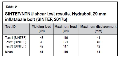
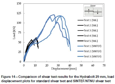
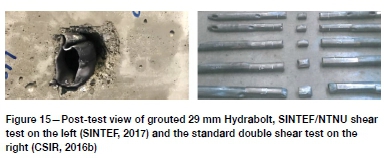
Tables V and VI show shear test results for the two different methods; load-displacement behaviours of the bolts are shown in Figures 14 and 15. For the SINTEF/NTNU shear test, the mean maximum load and displacement are 119 kN and 41 mm respectively. For the direct shear test, the mean maximum load and displacement are 60 kN and 11 mm respectively.
Discussion and analysis
Comparison of pull test results (standard direct pull test - SINTEF/NTNU test)
The similarity of the results obtained by the two test methods shows that tensile tests performed with the SINTEF/NTNU rockbolt testing rig can be approximated using a steel tube with a rockbolt installed in either resin or grout. The real benefit of the SINTEF/NTNU apparatus is its ability to better simulate a bolt hole like those in which rockbolts are installed underground. Since the bolt hole used in the test is drilled into the concrete blocks, the roughness of the borehole is similar to that of the borehole underground. Another advantage of this test method over the standard test method is the fact that it is easier to simulate the actual transverse stiffness (ASTM, 2008) of an actual bolt hole.
While this may not have a significant impact on the test results for a fully encapsulated rockbolt, it can significantly impact the performance of a rockbolt that relies on some form of friction or mechanical anchoring. In such cases, the SINTEF/NTNU testing method is potentially a more accurate representation of what will be experienced underground.
Comparison of shear test results (standard direct shear test - SINTEF/NTNU test)
The maximum loads and displacements of the bolts obtained with two shear test methods are quite different. Earlier shear tests carried out by Stjern (1995) show the same trend. The higher capacities found using the SINTEF/NTNU full-scale test rig may be explained by the crushing of the concrete host blocks and the grout, which facilitates bending of the bolt shank and results in almost pure tensile stresses in the bolt at failure (Stjern, 1995). When interpreting the shear capacities of the bolts, the influence of the shear resistance from the joint was not taken into account. The bolt can impart a wedge effect to the planes, forcing the surfaces apart and hence suspending the shear contribution from the joint when the bolt is drawn into the joint (Stjern, 1995).
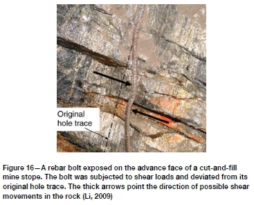
In the standard shear tests as performed above, the shearing load applies somewhat of a guillotine effect to the bolts. The shear capacity results found from pure shear tests carried out in the guillotine jig can be regarded as minimum values (Stjern, 1995). The failure surfaces of the ruptured bolts tested in the full-scale rig are more comparable to bolt failures seen in-situ than those from the guillotine tests (Stjern, 1995), as can be seen in Figure 16. Shear failure of rockbolts underground is rarely a pure shear failure of a guillotine type. This is the value of the SINTEF/NTNU testing procedure.
If a rock engineer were to design for the shear capacity (load and displacement) based on the results of the standard shear test, a more extensive (and expensive) support system may be required compared to a potentially more cost-effective support system based on results from the SINTEF/NTNU test rig.
The SINTEF/NTNU testing procedure has other benefits. One such benefit is that the material used to install/test the rockbolt can be designed to approximate the host rock in which the bolt will be used. Another benefit is the ability to test a combination of tensile and shear loading in a single test (Chen, 2014).
Conclusion
The pull test capacities resulting from the SINTEF/NTNU and standard tests are quite similar for the types of bolt tested.
> SINTEF/NTNU mean maximum load and displacement of 236 kN and 164 mm
> Standard pull test mean maximum load and displacement of 227 kN and 160 mm.
The SINTEF/NTNU test gave higher shear test capacities than the standard shear test. Both load and displacement are higher.
> For the PAR1 25 mm fully grouted energy-absorbing bolt the maximum load ratio was 1.2 and the displacement ratio was 2.8 between the two test methods.
> For the Hydrabolt 29 mm inflatable bolt the maximum load ratio was 2.0 and the displacement ratio was 3.7 between the two test methods.
The higher test results may be due to the fact that the loading is not purely shear, and a tensile contribution is present, but this varies with the type of bolt and bolt design (Li, 2010)
The SINTEF/NTNU test produces a better representation of reality compared to standard direct tests, since the bolt is installed in simulated hard rock conditions
The standard shear tests are more suitable for measuring the material minimum shear capacity of a bolt used underground.
Acknowledgements
Our thanks to chief scientist and Professor II Eivind Gr0v at SINTEF/NTNU for helpful suggestions regarding this paper.
References
ASTM. 2008. Standard test methods for laboratory determination of rock anchor capacities by pull and drop tests. D7401. West Conshohocken, PA. [ Links ]
Chen, Y. 2014. Experimental study and stress analysis of rock bolt anchorage performance. Journal of Rock Mechanics and GeotechnicalEngineering, vol. 6. pp. 428-437. [ Links ]
CSIR. 2016a. Shear testing of five grout bar capsules. Certificate no. T24529. CSIR, Johannesburg, South Africa. [ Links ]
CSIR. 2016b. Shear testing of five Hydrabolt assemblies (029 mm SAE1010, 1.8 wall thickness). Certificate no. T24358. CSIR, Johannesburg, South Africa. [ Links ]
CSIR. 2015. Test of ten bolts (20mm PAR1 Resin Bolts). Certificate no. T23352. CSIR, Johannesburg, South Africa. [ Links ]
Li, Ce. 2009. Field observations of rock bolts in high stress rock masses. Rock Mechanics and Rock Engineering, vol. 43, no. 4. pp. 491-496. [ Links ]
Li, e.e. 2010. A new energy-absorbing bolt for rock support in high stress rock masses. International Journal of Rock Mechanics and Mining Sciences, vol. 47, no. 3. pp. 396-404. [ Links ]
SINTEF. 2017a. Full scale rock bolt testing: Testing of strength and deformation properties of 25 mm Par1 rock bolts. Report no. SBF2017F0007. Trondheim, Norway. [ Links ]
SINTEF. 2017b. Full scale rock bolt testing: Testing of strength and deformation properties of rock bolt type Hydrabolt 29 mm. Report no. 2017:00004. Trondheim, Norway. [ Links ]
SINTEF. 2016. Full scale rock bolt testing: Testing of strength and deformation properties of Mp1 and Par1 bolts. Report no. SBF2016F0470. Trondheim, Norway. [ Links ]
Stjern, G. 1995 Practical performance of rock bolts. Doctoral thesis, University of Trondheim, Norway. [ Links ] ♦
 Correspondence:
S.A. Hagen
simon.a.hagen@sintef.no
Received: 23 Jun. 2019
Revised: 20 Aug. 2019
Accepted: 30 Aug. 2019
Published: January 2020

