


Services on Demand
Article
 English (pdf)
 Article in xml format
 Article references
Indicators

Related links
-
 Cited by Google
 -
 Similars in Google
Share

 Permalink
Journal of the Southern African Institute of Mining and Metallurgy
On-line version ISSN 2411-9717
Print version ISSN 2225-6253
J. S. Afr. Inst. Min. Metall. vol.119 n.12 Johannesburg Dec. 2019
http://dx.doi.org/10.17159/2411-9717/767/2020
GENERAL PAPERS
Influence of layered joints on zonal disintegration in deep rock masses under coupled high in-situ axial stress and blasting load
P. YuanI, II, III; Y. XuI, II, III
ISchool of Civil Engineering and Architecture, Anhui University of Science and Technology, Huainan, Anhui, China
IIState Key Laboratory of Mining Response and Disaster Prevention and Control in Deep Coal Mines, Anhui University of Science and Technology, Huainan, Anhui, China
IIIEngineering Research Center of Underground Mine Construction, Ministry of Education, Anhui University of Science and Technology, Huainan, Anhui, China
SYNOPSIS
Zonal disintegration is a characteristic failure mode of deep rock masses under coupled high in-situ axial stress and blasting load. PFC3D numerical simulations were carried out to investigate the influence of inclination angle of widely spaced, layered joints on zonal disintegration. The results indicate that after the four-step blasting procedure, nearly circular contact force chains, which are approximately concentric with the surface of the tunnel, are formed in both intact rock masses and rock masses with layered joints. The number of tension cracks is much greater than that of shear cracks; hence, tension failure predominates as the failure mode for zonal disintegration. Corresponding to the four-step blasting, a time-dependent characteristic is apparent for crack propagation and released strain energy evolution during the advance of the tunnel. Zonal disintegration can be intensified by extending the duration of the blasting load, and alleviated by extending the blasting rise time. The inclination angle of layered joints has a significant effect on zonal disintegration. With an increase of inclination angle, both the number of cracks and released strain energy first increase and then decrease, which is consistent with the distribution of contact force chains. When the inclination angle of layered joints is 60°, the joints present a strong influence on intensifying the zonal disintegration.
Keywords: zonal disintegration, layered joints, inclination angle, particle flow code, contact force chain.
Introduction
With the continuing depletion of shallow mineral resources, deep mining is imperative and has become a topic of great interest in China (Fairhurst, 2017; Xie et al., 2017). During deep mining, some unique engineering phenomena, such as zonal disintegration, large deformation, and rockbursts, occur frequently (Qian and Zhou, 2011; Yang et al., 2017 ).
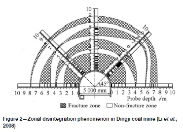
Due to stress distribution and blasting-induced damage, an excavation disturbed/damage zone (EDZ) is formed around an underground excavation (Wang et al., 2009). As shown in Figure 1a, a loose zone, plastic zone, and elastic zone are generally evident around the excavation in shallow situations (Tsang, Bernier, and Davies., 2005; Tian et al., 2019). Zonal disintegration is a nonlinear and characteristic failure mode in deep rock masses, and is quite distinct from failure modes in shallow situations, being characterized by alternating fracture zones and non-fracture zones (Yuan, 2016; Chen et al., 2017) as shown in Figure 1b. Zonal disintegration was first identified in Doornfontein gold mine in South Africa at about the -2300 m level (Adams and Jager, 1980). In China, zonal disintegration was detected by borehole video camera in Ding'i coal mine of Huainan mining area at the -910 m level (Li et al., 2008) (Figure 2).
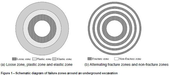
As indicated in Figure 1b and Figure 2, there are several fracture zones around an underground excavation. Previous researchers (Kurlenya and Oparin, 1996; Chen and Zhang, 2011; Mirenkov, 2014) have shown that the geometric characteristics of fracture zones in zonal disintegration phenomena are almost invariant with respect to the initial radius of the underground excavation, and the scale factor for the radii of the fracture zones can be described as ni-1 with reference to the initial radius of the excavation, where i is the sequence number of the fracture zone (i = 1, 2, 3,...). The scale factor n has been variously reported to be 1.1 (Chen and Zhang, 2011), V2 (Kurlenya and Oparin, 1996), and S (Mirenkov, 2014). The exact value of the scale factor for zonal disintegration is closely associated with the in-situ stress and mechanical characteristics of the surrounding rock (Chen and Zhang, 2011).
Based on in-situ monitoring in Dingji coal mine, Zhang, Xue, and Duan (2018) investigated the formation process of zonal disintegration by physical model tests and found that zonal disintegration formed gradually after completion of the excavation. Qi et al., (2017) developed a strain gradient model and found two necessary conditions for zonal disintegration -high initial in-situ stress and softening. Based on strain gradient theory and continuum damage mechanics, an elastic damage softening model was established for zonal disintegration, and the corresponding energy damage failure criterion was also proposed (Zhang et al., 2017). According to Chen et al., (2017), the circular fracture is initiated and extends when the peak stress intensity factor at the elastic-plastic boundary exceeds the fracture toughness KIC and the circular fracture boundary acts as a new 'excavation' for the constant formation of circular fracturing. Jia, Yang, and Yu (2012) stated that the failure patterns of the surrounding rock mass were mainly controlled by the multi-axial stress state, and high in-situ axial stress along the tunnel axis was essential for zonal disintegration. Yuan et al., (2014) indicated that the key factor in zonal disintegration was the predominant radial tension breakage around the deep tunnel. As the formation of fracture zones in zonal disintegration is irreversible, the occurrence of irreversible strains led to incompatibility deformation of the rock mass, which indicated the internal geometrical structure of the rock in non-Euclidean geometric space from the mathematical viewpoint (Guzev and Paroshin, 2001). Based on the deformation incompatibility condition, the equilibrium equation, and the density of free energy, a non-Euclidean continuum model was proposed to analyse the stress field distribution around the tunnel. Radial stress and circumferential stress around the tunnel were obviously fluctuant or wave-like in order for zonal disintegration to occur (Zhou and Qian, 2013). Physical model tests under blasting load were carried out (Xu and Yuan, 2015; Yuan, 2016; Yuan, Xu, and Xue, 2016). Peak radial blasting load was found to play an important role in the radial thickness of the fracture zone near the excavation (Yuan, 2016). By considering both high in-situ axial stress and blasting load, Yuan and Xu (2018) studied the zonal disintegration using elastic stress field analyses and the modified Hoek-Brown failure criterion. According to Bi and Zhou (2015), dynamic load and high in-situ stress are two dominant causes of zonal disintegration. In summary, both the high in-situ axial stress along the tunnel axis and blasting load are essential for zonal disintegration (Zuo et al., 2011).
Joints are important structural features that are widely distributed in rock masses. The failure and stability of rock masses are not only related to the strength of intact rock, but also controlled by joint characteristics (Yang and Liu, 2012; Yang et al., 2017). Feng et al., (2018) investigated the effect of pre-existing fractures on zonal disintegration and found that due to their the relatively low strength, such fractures within high excavation-induced in-situ stress concentrations would open and propagate and generate new fractures nearby. Zhou, Song, and Qian (2011) established a non-Euclidean model for deep, crack-weakened rock masses due to the incompatible deformation of deep rock masses within non-Euclidean geometric space. Zhang et al., (2014) studied the effect of soft interlayers on zonal disintegration and found that the smaller the spacing between soft interlayers, the greater the extent of fracture zones.
Zonal disintegration, with its characteristic alternating distribution of fracture zones and non-fracture zones, is closely associated with high in-situ axial stress and blasting excavation (Yuan and Xu, 2018). To investigate the Influence of parallel joint sets (also called layered joints) on zonal disintegration in rock masses, we carried out numerical simulations of zonal disintegration under coupled high in-situ axial stress and blasting load by Particle Flow Code in 3D (PFC3D). Then, the influence of layered joints on zonal disintegration was analysed from a perspective of contact force chain, crack propagation, and released strain energy evolution.
PFC3D model for rock masses with layered joints
PFC3D model
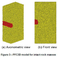
Taking the high in-situ stress deep tunnel in Dingji coal mine (Li et al., 2008) as the engineering background, PFC3D numerical simulations were carried out for intact rock masses and rock masses with layered joints under coupled high in-situ axial stress and blasting loads. As seen from Figure 2, the tunnel cross-section is a semicircular arch crown with vertical walls, 3.88 m high and 5.00 m wide. Due to the symmetry of the tunnel structure, only half of the tunnel is modelled. The dimensions of the rock mass model are 10.00 m along the tunnel axis, 15.00 m in the transverse direction, and 30.00 m along the vertical direction.
In numerical simulations, high computational precision requires a small particle size, which will lead to longer running times and require a high level of computing capacity. According to the research of Ding et al., (2014), the influence of particle size in PFC3D can be ignored when the ratio of model size to the median particle size exceeds 25. Therefore, the minimum particle radius was selected as 0.20 m, and the maximum to minimum particle radius ratio set as 1.66. The PFC3D model for intact rock masses, with 32 049 particles, is shown in Figure 3. Red particles in Figure 3 indicate the tunnel.
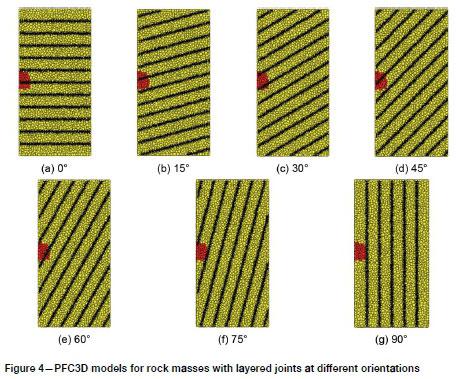
The inclination angle of the layered joints was varied from 0° to 90° with an increment of 15°. Seven inclination angles were considered: 0°, 15°, 30°, 45°, 60°, 75°, and 90°. The spacing between the layered joints was set at 2.50 m. The PFC3D models for rock masses with layered joints are shown in Figure 4. Black areas indicate the positions of the layered joints.
Microscopic parameters of the PFC3D model
In PFC3D, the particles are rigid spherical balls with a finite mass and they can be bonded together at contact. Bonds between particles can be envisaged as a kind of 'glue' joining the particles. There are two standard bond models - the parallel bond and the contact bond. The parallel bond is of a finite size, while the contact bond is of a vanishingly small size and acts only at the contact point between adjacent particles (Potyondy and Cundall, 2004; Itasca, 2008). The parallel bond can transmit both a force and a moment, while the contact bond transmits only a force. In PFC3D, slip behaviour is also provided for two contacting particles and is defined by the particle friction coefficient. The slip behaviour is always active unless a contact bond is present (Itasca, 2008). Note that slip behaviour is activated when a contact bond is broken.
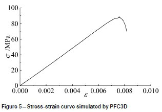
Appropriate micromechanical parameters are vital for PFC3D (Li et al., 2016). In PFC3D numerical simulations, the parallel bond model was adopted for rock materials by representing the rock as a cemented granular material (Cong et al., 2015). A particle can be defined by three parameters: the Young's modulus at each particle-particle contact, normal to shear stiffness ratio of the particle, and particle friction coefficient. A parallel bond can be defined by five parameters: Young's modulus of each parallel bond, normal to shear stiffness ratio of the parallel bond, radius multiplier, normal strength, and shear strength. The parallel bond radius equals the radius multiplier times the minimum radius of the two bonded particles. Microscopic parameters for the PFC3D model were obtained by trial and error. Referring to previous research (Xu, 2011), a series of uniaxial compressive tests was first carried out by PFC3D considering various microscopic parameters, then an adaptive neural network was trained and used to estimate the microscopic parameters. Finally, the microscopic parameters were adjusted by comparing the numerically simulated mechanical properties with the experimentally determined properties. For particles in PFC3D, the Young's modulus at each particle-particle contact, particle friction coefficient, and normal to shear stiffness ratio were set as 12 GPa, 0.7, and 1, respectively. For parallel bonds in PFC3D, the Young's modulus of each parallel bond, normal to shear stiffness ratio, and radius multiplier were set as 12 GPa, 3, and 1, respectively. The mean value and standard deviation of normal parallel bond strength are 70 MPa and 5 MPa. The mean value and standard deviation of shear parallel bond strength are 65 MPa and 5 MPa. According to previous work (Li et al., 2008), the experimentally determined uniaxial compressive strength, Young's modulus, and Poisson's ratio of a rock specimen from Ding'i coal mine were 88.55 MPa, 12.97 GPa, and 0.268, respectively. The simulated uniaxial compressive strength, Young's modulus, and Poisson's ratio are 88.33 MPa, 12.09 GPa, and 0.258, respectively. The uniaxial compressive stress-strain curve simulated by PFC3D is shown in Figure 5.
In PFC3D, a set of joint planes was created with the 'jset' command and the parallel bonds falling on the 'oint planes were deleted. Then, contact bonds were assigned to the contacts between particles falling on opposite sides of the joint planes (Kulatilake, Malama, and Wang, 2011). The normal and shear contact bond strength values were set as 7.0 x 10⁶ N and 6.5 x 10⁶ N, respectively. When a contact bond was broken, slip behaviour was activated. The friction coefficient of particles falling on opposite sides of the joint planes was set as 0.3.
High in-situ axial stress and blasting load
In numerical simulations, the high in-situ axial stress was firstly applied to the PFC3D model, then blasting excavation was carried out in four steps. The advance of each blasting step was set at 2.50 m, and 5000 time-steps were run in each blasting step. According to Zhang et al., (2013), an essential condition for zonal disintegration is that the maximum principal stress is parallel to the tunnel axis and exceeds 1.5 times the uniaxial compressive strength of the surrounding rock mass. Hence, the stress applied on the front and back walls was set as 135.00 MPa. At the depth of the deep tunnel in Dingji coal mine, gravity stress was 25.10 MPa, and the coefficient of horizontal pressure was assumed as 1.0. Therefore, the stress applied on the upper, lower, and side walls was 25.10 MPa. With the FISH programming language embedded within PFC3D, the numerical servo control can maintain a specified wall stress by adjusting the wall velocity (Itasca, 2008). In PFC3D numerical simulations, servo control was applied to maintain the high in-situ axial stress during blasting excavation.
During simulated blasting excavation, the particles within the tunnel were deleted, then a triangular blasting load pulse, shown in Figure 6, was applied to the particles on the surface of the tunnel. The direction of blasting load is along its normal direction (Yan et al., 2013). As seen from Figure 6, the rise time of the triangular blasting load pulse is trand its duration is td. Referring to a previous study (Yang et al., 2013), the rise time and duration of the triangular blasting load pulse can be determined as follows.
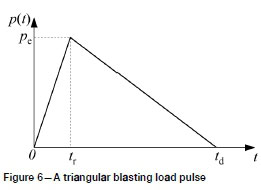
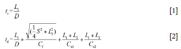
where L1is the charge length, L2is the stemming length, S is the spacing between adjacent blast-holes, D is the detonation velocity of the explosive, Cpis the P-wave velocity of the rock mass, Cfis the average velocity of crack propagation (Cf= 0.2 to 0.3Cp), and Cu1and Cu2are the average velocities of rarefaction waves in the detonation gases.
Referring to the common blasting practice in underground excavation, the rise time and duration of the triangular blasting load pulse are 2 ms and 7 ms (Yan et al., 2013). As the charge length, stemming length and spacing between adjacent blast-holes vary with various blasting designs, three kinds of blasting loads are considered. The rise time and duration are 2 ms and 7 ms respectively for blasting load I, 4 ms and 14 ms for blasting load II, and 6 ms and 14 ms for blasting load III.
Another important parameter of blasting load is the peak equivalent blasting load. According to Yan et al., (2013), the peak equivalent blasting load can be expressed as:
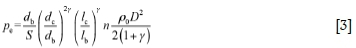
where dband lbare the diameter and depth of the blast-hole, dc and lcare the diameter and length of explosive, S is the spacing between adjacent blast-holes, p0and D are the density and detonation velocity of the explosive, y is the ratio of the specific heats for the detonation gases, and n is the stress intensification coefficient caused by the detonation gases.
Based on blasting practice in deep rock masses, the diameter of the blast-hole (db) is 45 mm, spacing s between blast-holes is 500 mm. and lcilbis 0.5. The ratio of the specific heats for the detonation gases (y) is 3 and the stress intensification coefficient caused by the detonation gases (n) is 10. The density p0and detonation velocity D of explosive are 1100 kglm and 3262 mls respectively. Hence, the peak equivalent blasting load peis calculated to be 36.50 MPa.
Influence of blasting load on zonal disintegration in intact rock masses
Numerical simulation validation
In PFC3D, contacts exist between two particles or between a particle and a wall, and forces are transmitted from one particle to the next via their contacts (Itasca, 2008). Under external loads, a contact force chain is generated between particles in contact (Sun and Wang, 2008). A force chain, also called a contact force chain, is a linear string of at least three rigid particles in point contact (Itasca, 2008). It represents the external forces distributed through filament-like particles and the direction of contact force chains coincide with the principal stress directions of the external load. Contact force chains in intact rock masses before and after blasting excavation for blasting load I are shown in Figure 7.
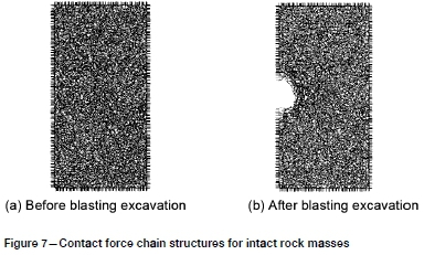
As seen from Figure 7, contact force chains are disordered before blasting excavation, while after blasting excavation they have an approximately circular distribution around the tunnel and degenerate into a disordered distribution at a distance from the tunnel. As parallel bonds are used in PFC3D, the bonded particles will transform into granular particles when the parallel bond is broken. The granular particles flow into the tunnel space and contacts between granular particles are eliminated. As forces are transmitted from one particle to the next via their contacts, circular contact force chains around the tunnel indicate a circular distribution of load-bearing particles, which implies a non-fracture zone in deep rock masses. There are two circular contact force chains around the tunnel. Particles between circular contact force chains or between circular contact force chains and the surface of the tunnel are in fracture zones. Quantitative analysis of the circular distribution of contact force chains is carried out by measuring the distance between the circular contact force chains and the designed tunnel surface. After quantitative analysis, the radii of the two circular contact force chains are approximately 3.26 m and 3.85 m. Hence, the radii of the first and second fracture zones are 2.88 m and 3.56 m respectively. The average scale factor for radii of fracture zones is about 1.20, which is in good accordance with the results of Li et al., (2008), Chen and Zhang (2011), and Chen et al., (2017). As the in-situ axial stress in PFC3D numerical simulations is less than 2.0 times the uniaxial compressive strength, only two fracture zones are presented, as opposed to the four fracture zones found by Chen and Zhang (2011) and Chen et al., (2017). Therefore, the PFC3D model is shown to be appropriate for the following analyses.
Crack propagation during blasting excavation
Figure 8 illustrates the propagation of tensile and shear cracks for three kinds of blasting loads during the four-step blasting excavation.
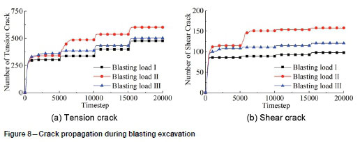
As seen from Figure 8, the number of both tension cracks and shear cracks increases with the advance of blasting excavation, and the number of tension cracks is much greater than the number of shear cracks. Furthermore, a time-dependent characteristic is apparent. Four sharp increments in crack propagation imply four steps of blasting excavation, and the greatest increment in the number of cracks occurs mainly in the first 500 time-steps of each blast. Most of tension and shear cracks are generated in the first blasting step. For instance, the number of tension and shear cracks for blasting load I after the four-step blasting excavation is 477 and 98 respectively. There are already 303 tension cracks and 86 shear cracks after the first blasting step, accounting for 63.5% and 92.5% of the total number of tension and shear cracks.
Hence, tension failure is the predominant failure mode for a deep tunnel under coupled high in-situ axial stress and blasting load. This is consistent with the findings of Yuan et al., (2014); namely, that zonal disintegration is the result of tension failure in the radial direction. According to Figure 8, extending the duration of the blasting load will increase the number of tension and shear cracks, while extending the rise time will decrease the number of both types of crack.
Released strain energy evolution during blasting excavation
The released strain energy Esfor three kinds of blasting load during the four-step blasting process is shown in Figure 9.
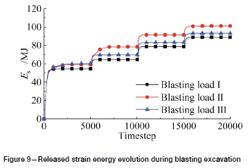
As seen from Figure 9, the strain energy stored in the surrounding rock is released during the four-step blasting procedure. The distribution of released strain energy is similar to that of crack propagation. A time-dependent characteristic is also apparent. After the four-step blasting process, the total released energy is 89.0 MJ for blasting load I, 101.3 MJ for blasting load II, and 93.3 MJ for blasting load III. Extending the duration of the blasting load will accelerate the strain energy release, while extending the rise time will reduce the strain energy release.
Influence of layered joints on zonal disintegration
Contact force chains in rock masses with layered joints
Blasting load I was adopted for PFC3D numerical simulations of rock masses with layered joints. Contact force chains for various inclination angles of layered joints after the four-step blasting excavation are shown in Figure 10. A black contact force chain represents compression, and a red chain represents tension. Most of the contact force chains are compressive, and only a few tensile contact force chains are located in the layered joints.
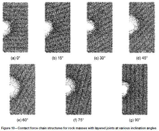
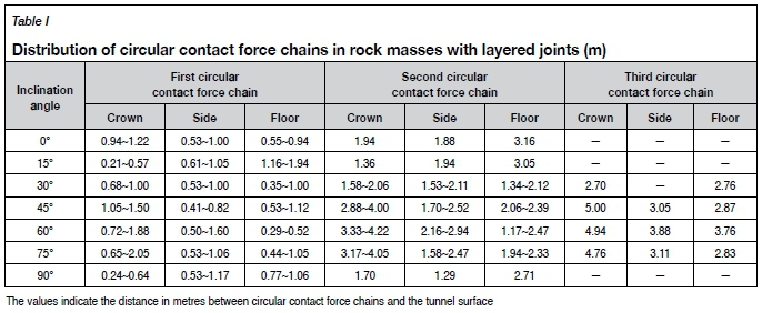
As seen from Figure 10, circular contact force chains, which are approximately parallel to the surface of the tunnel, are present. In PFC3D, forces are transmitted from one particle to the next via their contacts. Circular contact force chains around the tunnel indicate circular distribution of load-bearing particles, which implies a non-fracture zone. On the contrary, when a bond between particles is broken, bonded particles are transformed into granular particles. Contact force chains are eliminated in fracture zones when granular particles flow into the tunnel space. Therefore, blank areas between circular contact force chains correspond to fracture zones. With alternating distribution of circular contact force chains, rock masses with layered joints undergo zonal disintegration. Some tensional contact force chains are generated in the pre-existing layered joints. When the inclination angle of the layered joints is less than 15°, fracture zones in the tunnel floor are much more serious than in other positions. At inclination angles of layered joints greater than 15°, fracture zones at the tunnel crown are more serious than in other positions, causing slip failure along the layered joints. With an increase in inclination angle, the extent of fracture zones around the tunnel first increases and then decreases. Fracture zones are at a maximum at an inclination angle of 60° and reach their minimum at an inclination angle of 90°.
By quantitative analysis of circular contact force chains in rock masses with layered joints, the distribution of circular contact force chains is obtained, which is shown in Table I.
Crack propagation in rock masses with layered joints
After the four-step blasting process, the number of tension and shear cracks in the PFC3D model varies with the inclination angle of the layered joints, as shown in Figure 11.
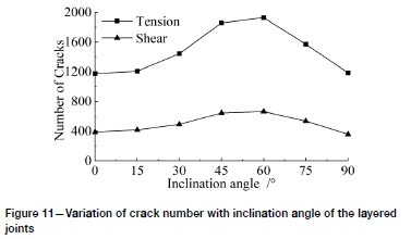
As seen from Figure 11, both tension and shear cracks are present around the deep tunnel. Tension failure is the predominant fracture mode for rock masses with layered joints. With increasing inclination angle, the number of tension cracks and shear cracks first increases and then decreases. The number of cracks for rock masses with layered joints is much higher than that for an intact rock mass. Therefore, the presence of layered joints substantially accelerates crack propagation.
After the four-step blasting process, the tension to shear crack ratio (TC/SC) varies with the inclination angle of layered joints, as shown in Figure 12.
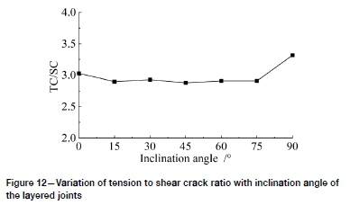
As seen from Figure 12, the tension to shear crack ratio varies from 2.88 to 3.32 for rock masses with layered joints. However, the tension to shear crack ratio for intact rock masses under blasting load I is 4.87. Hence, the presence of layered joints reduces the tension to shear crack ratio, which can be attributed to shear crack propagation by slip failure on the layered joints.
Released strain energy evolution for rock masses with layered joints
The variation in released strain energy Es with increasing joint inclination angle after the four-step blasting excavation is shown in Figure 13.
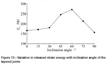
As seen from Figure 13, the released strain energy first increases, then decreases with increasing inclination angle, which is similar to the trend in the number of tension and shear cracks. The released strain energy reaches a maximum at an inclination angle of 60° and is at a minimum at an inclination angle of 90°.
For rock masses with layered joints, the released strain energy varies from 157.5 MJ to 271.6 MJ. However, it is 89.0 MJ for intact rock masses under blasting load I. Hence, the pre-existing layered joints substantially increase the release of stored strain energy.
Conclusion
According to PFC3D numerical simulations for intact rock masses under coupled high in-situ axial stress and blasting loads, two approximately circularly distributed contact force chains are generated after the four-step blasting process. The average scale factor for the radii of the fracture zones is about 1.20.
A time-dependent characteristic is evident for crack propagation and released strain energy evolution during the advance of the tunnel. The number of tension cracks is much greater than that of shear cracks. Hence, tension failure is the predominant failure mode during zonal disintegration.
Extending the duration of the blasting load pulse generates more tension and shear cracks and accelerates the strain energy release. Extending the rise time reduces the number of tension and shear cracks and slows down the strain energy release.
Nearly circular contact force chains, which are approximately parallel to the tunnel surface, are formed in rock masses with layered joints. The extent of the fracture zones is significantly affected by the inclination angle of layered joints. At an inclination angle below 15°, fracture zones in the tunnel floor are much serious than in other positions. At inclination angles greater than 15°, fracture zones at the tunnel crown are more evident than in other positions, causing slip failure along the layered joints.
With increasing inclination angle, both the number of cracks and the released strain energy first increase and then decrease, which is consistent with the distribution of contact force chains.
The fracture zone, number of cracks, and released strain energy all reach a maximum at an inclination angle of 60°, which indicates the strong influence of layered joints in intensifying zonal disintegration.
Acknowledgements
This research was supported by the Anhui Provincial Natural Science Foundation (1808085QE148), Project funded by China Postdoctoral Science Foundation (2018M642504), National Natural Science Foundation of China (51174004), Natural Science Research Project of Colleges and Universities in Anhui Province (KJ2017A097), Young Teacher Scientific Research Project of Anhui University of Science and Technology (QN201607), Doctoral Fund Project of Anhui University of Science and Technology (11674), and Science and Technology Project of Department of Housing and Urban-Rural Development of Anhui Province (2017YF-08).
ORCiD ID:
P. Yuan: https://orcid.org/0000-0003-4733-1731
Y. Xu: https://orcid.org/0000-0001-9060-1077
References
Adams, C.R. and Jager, A.J. 1980. Petroscopic observations of rock fracturing ahead of stope faces in deep-level gold mines. Journal of the South African Institute of Mining and Metallurgy, vol. 80, no. 6. pp. 204-209. [ Links ]
Bi, J. and zhou, X.P. 2015. Numerical simulation of zonal disintegration of the surrounding rock masses around a deep circular tunnel under dynamic unloading. International Journal of Computational Methods, vol. 12, no. 3. pp. 1550020. https://doi.org/10.1142/S0219876215500206 [ Links ]
Chen, X., Li, T., Xu, J., and Li, Y. 2017. Mechanism of zonal disintegration phenomenon (ZDP) and model test validation. Theoretical and Applied Fracture Mechanics, vol. 88. pp. 39-50. [ Links ]
Chen, X.G. and Zhang, Q. Y. 2011. Mechanism analysis of phenomenon of zonal disintegration in deep tunnel model test under high geostress. Rock and Soil Mechanics, vol. 32, no. 1. pp. 84-90. [ Links ]
Cong, Y., Wang, Z.Q., Zheng, Y.R., and Feng, X.T. 2015. Experimental study on microscopic parameters of brittle materials based on particle flow theory. Chinese Journal of GeotechnicalEngineering, vol. 37, no. 6. pp. 1031-1040. [ Links ]
Ding, X., Zhang, L., Zhu H., and Zhang, Q. 2014. Effect of model scale and particle size distribution on PFC3D simulation results. Rock Mechanics and Rock Engineering, vol. 47, no. 6. pp. 2139-2156. [ Links ]
Fairhurst, C. 2017. Some challenges of deep mining. Engineering, vol. 3, no. 4. pp. 527-537. [ Links ]
Feng, X.T., Guo, H.S., Yang, C.X., and Li, S.J. 2018. In-situ observation and evaluation of zonal disintegration affected by existing fractures in deep hard rock tunneling. Engineering Geology, vol. 242. pp. 1-11. [ Links ]
Guzev, M.A. and Paroshin, A.A. 2001. Non-Euclidean model of the zonal disintegration of rocks around an underground working. Journal of Applied Mechanics and Technical Physics, vol. 42, no. 1, pp.131-139. [ Links ]
Itasca. 2008. PFC3D - Particle flow code in 3-dimensions, version 4.0. User's manual, Itasca Consulting Group Inc, Minneapolis, MN. [ Links ]
Jia, P., Yang, T.H., and Yu, Q.L. 2012. Mechanism of parallel fractures around deep underground excavations. Theoretical and Applied Fracture Mechanics, vol.61. pp. 57-65. [ Links ]
Kulatilake, P.H.S.W., Malama B., and Wang, J. 2001. Physical and particle flow modeling of jointed rock block behavior under uniaxial loading. International Journal of Rock Mechanics and Mining Sciences, vol. 38, no. 5. pp. 641-657. [ Links ]
Kurlenya, M.V. and Oparin, V.N. 1996. Scale factor of phenomenon of zonal disintegration of rock, and canonical series of atomic and ionic radii. Journal of Mining Science, vol. 32, no. 2. pp. 81-90. [ Links ]
Li, K.M., Li, Y.H., Xu, S., and An, L. 2016. Method to determine microscopic parameters of PFC2D numerical model. Journal of Northeastern University (Natural Science), vol. 37, no. 4. pp. 563-567. [ Links ]
Li, S., Wang, H., Qian, Q., Li, S., Fan, Q., Yuan, L., Xue, J., and Zhang Q. 2008. In-situ monitoring research on zonal disintegration of surrounding rock mass in deep mine roadways. Chinese Journal of Rock Mechanics and Engineering, vol. 27, no. 8. pp. 1545-1553. [ Links ]
Mirenkov, V. E. 2014. Zonal disintegration of rock mass around an underground excavation. Journal of Mining Science, vol. 50, no. 1. pp. 33-37. [ Links ]
Potyondy, D.O. and Cundall, P.A. 2004. A bonded-particle model for rock. International Journal of Rock Mechanics and Mining Sciences, vol. 41, no. 8, pp. 1329-1364. [ Links ]
Qi, C.Z., Li, K.R., Bai, J.P., Chanyshev, A.I., and Liu, P. 2017. Strain gradient model of zonal disintegration of rock mass near deep-level tunnels. Journal of Mining Science, vol. 53, no. 1. pp. 21-33. [ Links ]
Qian, Q. and Zhou, X. 2011. Quantitative analysis of rockburst for surrounding rocks and zonal disintegration mechanism in deep tunnels. Journal of Rock Mechanics and Geotechnical Engineering, vol. 3, no. 1. pp. 1-9. [ Links ]
Sun, Q.C. and Wang, G.Q. 2008. Review on granular flow dynamics and its discrete element method. Advances in Mechanics, vol. 38, no. 1. pp. 87-100. [ Links ]
Tian, M., Han, L., Meng, Q., Jin, Y., and Meng, L. 2019. In-situ investigation of the excavation-loose zone in surrounding rocks from mining complex coal seams. Journal of Applied Geophysics. vol. 168. pp. 90-100. [ Links ]
Tsang, C.F., Bernier, F., and Davies, C. 2005. Geohydromechanical processes in the Excavation Damaged Zone in crystalline rock, rock salt, and indurated and plastic clays - In the context of radioactive waste disposal. International Journal of Rock Mechanics and Mining Sciences, vol. 42, no, 1. pp. 109-125. [ Links ]
Wang, S.H., Lee, C.I., Ranjith, P.G., and Tang, C.A. 2009. Modeling the effects of heterogeneity and anisotropy on the excavation damaged/disturbed zone (EDZ). Rock Mechanics and Rock Engineering, vol. 42, no. 2. pp. 229-258. [ Links ]
Xie, H.P., Gao, F., Ju, Y., Ge, S.R., Wang, G.F., Zhang, R., Gao, M.Z., Wu, G., and Liu, J.Z. 2017. Theoretical and technological conception of the fluidization mining for deep coal resources. Journal of China Coal Society, vol. 42, no. 3. pp. 547-556. [ Links ]
Xu, G.A. 2011. Research on the mechanism and evolution law of rock deformation and cracking around deep tunnels. PhD thesis, China University of Mining and Technology. [ Links ]
Xu, Y. and Yuan, P. 2015. Model test of zonal disintegration in deep rock under blasting load. Chinese Journal of Rock Mechanics and Engineering, vol. 34, no. S2. pp. 3844-3851. [ Links ]
Yan, P., Li, T., Lu, W.B., Chen, M., and Zhou, C.B. 2013. Properties of excavation damaged zone under blasting load in deep tunnels. Rock and Soil Mechanics, vol. 34, no. S1. pp. 451-457. [ Links ]
Yang, S.Q., and Liu, X.R. 2012. Experimental investigation on dilatancy behavior of marble with pre-existing fissures under different confining pressures. Chinese Journal of Geotechnical Engineering, vol. 34, no. 12. pp. 2188-2197. [ Links ]
Yang, J., Lu, W., Chen, M., Yan, P., and Zhou, C. 2013. Microseism induced by transient release of in-situ stress during deep rock mass excavation by blasting. Rock Mechanics and Rock Engineering, vol. 46, no. 4. pp. 859-875. [ Links ]
Yang, S.Q., Chen, M., Jing, H.W., Chen, K.F., and Meng, B. 2017. A case study on large deformation failure mechanism of deep soft rock roadway in Xi'An coal mine, China. Engineering Geology, vol. 217. pp. 89-101. [ Links ]
Yang, X.X., Jing, H.W., Tang, C.A., and Yang, S.Q. 2017. Effect of parallel joint interaction on mechanical behavior of jointed rock mass models. International Journal of Rock Mechanics and Mining Sciences, vol. 92. pp. 40-53. [ Links ]
Yuan, L., Gu, J.C., Xue, J.H., and Zhang, X.Y. 2014. Model test research on the zonal disintegration in deep rock. Journal of China Coal Society, vol. 39, no. 6. pp. 987-993. [ Links ]
Yuan, P. 2016. Model test on zonal disintegration in deep rock mass under blasting load. PhD thesis, Anhui University of Science and Technology, China. [ Links ]
Yuan, P., and Xu, Y. 2018. Zonal disintegration mechanism of deep rock masses under coupled high axial geostress and blasting load. Shock and Vibration, vol. 2018, pp. 4957917. [ Links ]
Yuan, P., Xu, Y., and Xue, J.H. 2016. Model test of anchorage deep tunnel in blasting excavation. Chinese Journal of Rock Mechanics and Engineering, vol. 35, no. 9. pp. 1830-1836. [ Links ]
Zhang, Q.Y., Zhang, X.T., Xiang W., Chen, X.G., Cao, G.H., and Xu, X.B. 2013. Model test study of zonal disintegration in deep rock mass under different cavern shapes and loading conditions. ChineseJournal of Rock Mechanics and Engineering, vol. 32, no. 8. pp. 1564-1571. [ Links ]
Zhang, X.T., Zhang, Q.Y., Xiang, W., Gao, Q., Yuan, S.B., and Wang, C. 2014. Model test of zonal disintegration in deep layered jointed rock mass. Rock and Soil Mechanics, vol. 35, no. 8. pp. 2247-2254. [ Links ]
Zhang, Q., Zhang, X., Wang, Z., Xiang, W., and Xue, J. 2017. Failure mechanism and numerical simulation of zonal disintegration around a deep tunnel under high stress. International Journal of Rock Mechanics and Mining Sciences, vol. 93. pp. 344-355. [ Links ]
Zhang, X., Xue, J., and Duan, C. 2018. Research on formation process of zonal disintegration in deep rock mass based on filed monitoring and geomechanical model test. Geotechnical and Geological Engineering, vol. 36, no. 4. pp. 2725-2733. [ Links ]
Zhou, X., and Qian, Q. 2013. The non-Euclidean model of failure of the deep rock masses under the deformation incompatibility condition. Journal of Mining Science, vol. 49, no. 3. pp. 368-375. [ Links ]
Zhou, X.P., Song, H.F., and Qian, Q.H. 2011. Zonal disintegration of deep crack-weakened rock masses: a non-Euclidean model. Theoretical and Applied Fracture Mechanics, vol. 55, no. 3. pp. 227-236. [ Links ]
Zuo, Y.J., Ma, C.D., Zhu, W.C., Li, S.C., Gong, F.Q., and Chen, C.C. 2011. Model test study of mechanism of layered fracture within surrounding rock of tunnels in deep stratum tunneling under dynamic disturbance. Rock and Soil Mechanics, vol. 32, no. 10. pp. 2929-2936. [ Links ]
 Correspondence:
P. Yuan
Email: puy2012@126.com
Received: 29 May 2019
Revised: 13 Oct. 2019
Accepted: 28 Oct. 2019
Published: December 2019

