


Services on Demand
Article
 English (pdf)
 Article in xml format
 Article references
Indicators

Related links
-
 Cited by Google
 -
 Similars in Google
Share

 Permalink
Journal of the Southern African Institute of Mining and Metallurgy
On-line version ISSN 2411-9717
Print version ISSN 2225-6253
J. S. Afr. Inst. Min. Metall. vol.119 n.11 Johannesburg Nov. 2019
http://dx.doi.org/10.17159/2411-9717/686/2019
GENERAL PAPERS
Improving cathode morphology at a copper electrowinning plant by optimizing Magnafloc 333 and chloride concentrations
J.C. JacobsI; D.R. GrootI, II
IDepartment of Mining and Process Engineering, Namibia University of Science and Technology, Namibia
IIDepartment of Materials Science and Metallurgical Engineering, University of Pretoria, South Africa
SYNOPSIS
Electrowinning circuits normally use a number of additives in the electrolyte to promote smooth, compact deposits. These cathodes have the best levels of purity. When electrowinning is coupled to a solvent extraction operation, it is important to minimize the amount of surface-active additives used, as their presence tends to increase phase-disengagement times. In the present work the effects of Magnafloc 333 and chloride concentration were studied with the aim of minimizing the amounts currently being added, while producing an acceptable copper cathode morphology. Magnafloc 333 is a non-ionic polyacrylamide that promotes the plating of smooth, dense copper deposits with minimal impurities. Chloride is added to promote the growth of dense, fine-grained, low-impurity copper deposits on the cathode. A Hull cell was used for the test work. Optimum Magnafloc 333 and chloride concentrations for a synthetic plant electrolyte were found to be 0.01 g/L and 0.025 g/L, respectively. These concentrations were then used to plate laboratory-scale copper cathodes from synthetic and plant electrolytes. Scanning electron microscopy was used to analyse the morphology of the cathodes plated. Many polyhedral crystals were deposited from the synthetic electrolytes, but deposits from the plant electrolytes tended to be spherical, with a large degree of porosity at the lower Magnafloc 333 concentration of 0.01 g/L. Polyhedral deposits were associated with high-quality, smooth plated cathodes.
Keywords: Electrowinning, copper, Hull cell, Magnafloc 333, chloride ion.
Introduction
Copper cathode quality is of great importance because it is sold in its as-stripped state. Organic additives, such as Magnafloc 333, are added to the electrowinning circuit to ensure a smooth plated surface. This project aimed to establish a relationship between the concentrations of Magnafloc 333 and chloride ions and their effects on the cathode morphology.
Additive concentrations
Most Cu electrowinning plants use smoothing agents in their electrolytes to improve copper cathode quality. Additives promote the plating of smooth, dense copper deposits with minimal impurities (Davenport et al., 2011). Various additives are available, such as thiourea, gelatin, animal glue, polyacrylamides, polysaccharides, and saccharides, and are commonly used as levelling and brightening agents in copper electrodeposition and electrowinning. According to Muresan et al. (2000), thiourea decomposes, leading to contamination of the cathodic deposit with sulphur. In the past guar was the most commonly used additive in copper electrowinning, because of its compatibility with solvent extraction (Davenport et al., 2011) . It has been used as a levelling agent for more than 40 years to produce good quality copper cathodes (Cui, 2014). In recent years, guar has largely been superseded by synthetic products that allow better quality control of the product and are easier to prepare (Robinson et al, 2013). Magnafloc 333 is a very high molecular mass non-ionic polyacrylamide flocculant that undergoes hydrolysis in acid or alkaline solutions, but is stable under neutral conditions (Caulfield, 2002). Fabian, Ridd, and Sheehan (2006) studied the effect of activated polyacrylamide on the surface morphology of electrodeposited copper and found that the surface roughness with a diluted electrolyte was statistically lower than when the additive was either prepared in water, in full-strength electrolyte, or in alkaline solutions.
Cobalt is often added to minimize the corrosive degradation of the lead anodes normally used in the electrowinning of base metals from sulphate electrolytes (Mirza et al., 2016). Cobalt ions promote the evolution of oxygen at the anode rather than the oxidation of lead and lower the anode potential in the process (Nikoloski and Nicol, 2008) without materially affecting cathode quality.
Chloride in the electrolyte has both beneficial and detrimental effects on the electrowinning process. Chloride ions are usually present in electrolytes as a result of chloride transfer through solvent extraction, or are intentionally added as either hydrochloric acid or sodium chloride (Davenport et al., 2011). Chloride ion concentrations usually range from 0.02 g/L to 0.03 g/L (Cui, 2014). They promote the growth of dense, fine-grained, low-impurity copper deposits on the cathode. When using stainless-steel cathode blanks, the chloride ion concentration must be kept below approximately 0.03 g/L to avoid pitting corrosion on the anode surface (Beukes and Badenhorst, 2009). When pitting corrosion occurs, the copper will deposit in the pits, causing it to adhere to the cathodes and making it very difficult to strip the copper sheet from the cathode (Davenport et al., 2011). An undamaged, passive layer of controlled roughness on the stainless steel surface allows for both sufficient adherence and ease of stripping.
Hull cell
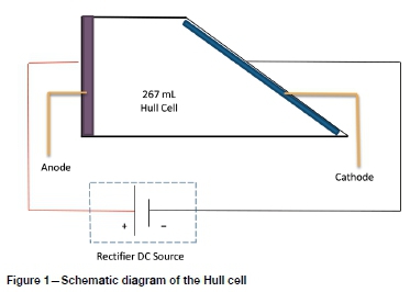
The Hull cell (see Figure 1) offers a simple and precise method of conducting plating tests with various electrolytes. The apparatus is an electroplating cell fabricated by Dr Richard Hull in 1939 that can aid in optimizing the following parameters (Gabe, 2007):
> The effect of impurities
> The effect of pH
> Additive concentrations
> Current density range
> Metal ion concentrations.
The Hull cell can also be used to determine the throwing power of electrolytes, and brightness levels and irregularity in plate deposits (Institute for Interconnecting and Packaging Electronic Circuits, 1997).
The Hull cell had a trapezoidal shape and a volume of 267 mL. The cathode is at an angle of 39° to the anode as shown in Figure 1. When an electrical current is supplied to the cell, the distance between the anode and cathode will determine the current density. The further away the cathode is from the anode, the lower the current density will be and thus a lower plating thickness can be expected. The separation distance determines the cell voltage. This geometry allows the test panel to be placed at an angle to the anode. As a result, the deposit is plated at different current densities that can be measured with a Hull cell ruler. The total current will determine the current density of the overlap area. For acid copper baths, it is suggested that copper be used as both cathode and anode (Kocour, 2018). This is to avoid the effects of lowering the copper concentration during plating.
The current density can be calculated using the formula given by Pletcher and Walsh (1993):

where I is the current density in mA/cm2 at any point on the cathode, i is the total current in amperes, and x is the distance in centimetres from the high current density end of the cathode to the point at which the current density is desired.
Experimental
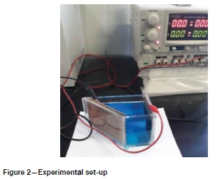
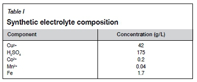
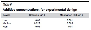
Initial test work was carried out using the Hull cell as shown in Figure 2. The synthetic electrolyte had the composition shown in Table I. The composition reflected that of the plant electrolyte, and was made up using laboratory-grade reagents, with the metals added as sulphate salts. The concentrations of chloride and Magnafloc 333 were varied according to a full factorial design and the values for the low, medium, and high levels are shown in Table II. The ranges were selected according to plant operating conditions, as well as aiming for minimum Magnafloc 333 concentrations, because lower concentrations would be more economical and less likely to affect the solvent extraction circuit. A constant current of 3 A was used to operate the Hull cell. The electrolyte was preheated to 45°C and the cell was placed inside a water bath to maintain the temperature of the electrolyte. Plating time for each run was 5 minutes. The copper electrodes were prepared for use by sanding with 35 μm sandpaper under running water. Each run was carried out in triplicate to test for reproducibility. The reproducibility was found to be very good as regards the morphologies seen on the different current density areas.
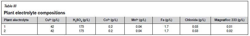
The results from the Hull cell experiments were used to conduct a second set of experiments using a conventional laboratory electrowinning cell. A lead anode and stainless-steel cathode were used. The back and edges of the cathode were masked to enable stripping of the copper deposits. The exposed areas were measured, and the values used to calculate the current density for each experiment. The electrolyte composition was the same as the synthetic electrolyte used in the Hull cell. The additive concentrations were varied. Chloride concentrations were 0.025 g/L and 0.03 g/L, and the Magnafloc 333 concentration was 0.01 g/L. The electrolyte temperature was maintained at 45°C in a water bath. The current in the cell was 0.63 A. The plating time for each experiment was 5 hours. Two runs were also conducted using plant electrolyte with compositions shown in Table III. Magnafloc 333 was added to to obtain electrolyte 2. The cathode was rinsed with water and dried before stripping the deposit.
Selected areas of deposits were studied using a Jeol IT300 scanning electron microscope (SEM).
Results and discussion
Hull cell results and discussion
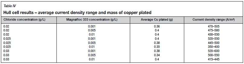
A benefit of using the Hull cell for test work is that deposit morphologies over a wide range of current densities can be investigated in a single experiment. At high current densities, poor morphologies are expected, with powdery and dendritic deposits, due to deposition occurring at, or close to, cathode surface boundary layer diffusion control for copper ions. At low current densities, deposition will occur under activation-control conditions, which is expected to result in fairly smooth deposits, although at low production rates. Figure 3 shows a cathode with the high current density region to the left. The deposit at high current density is dark in colour due to its very rough surface. Table IV shows the average amount of copper that was deposited under the various experimental conditions, as well as the widest current density ranges that gave an acceptable deposit morphology. A wide current density range is expected to make the electrowinning operation more robust. The widest current density range with an acceptable deposit morphology, shown in Figure 3, was obtained with an electrolyte containing 0.025 g/L chloride and 0.01 g/L Magnafloc 333. Based on the amount of copper deposited, the current efficiency was not optimal. This was not unexpected because the chloride and Magnafloc 333 concentrations were quite high, resulting in a relatively high inhibition intensity (Winand, 1992), which causes inhibition of the main cathodic process.
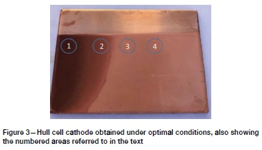
In area 1 (Figure 3) the current density was the highest; around 1291 A/m2. The deposit appeared dark and was very feathery and dendritic, as expected. This is due to extremely high rates of nucleation compared with the rate of growth. High rates of nucleation still occurred in region 2, where the current density was around 645 A/m2, which is approximately double the normal plant current density. Powdery deposits were obtained, as shown in Figure 4 (top image), with particle sizes up to about 10 μm.
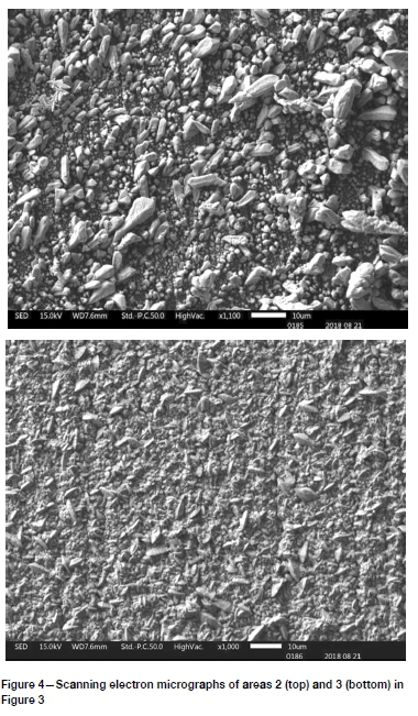
The best quality deposit was obtained in region 3, where the current density was 390 A/m2. This deposit was compact with a small grain size, generally less than 10 μm. On a micro scale, the surface was not very smooth, as seen in Figure 4 (bottom image), accounting for the dull finish seen in Figure 3.
Electrowinning results and discussion
Table V illustrates the stripped cathodes obtained in synthetic electrolytes with different chloride levels, and in two plant electrolytes with different Magnafloc 333 levels.
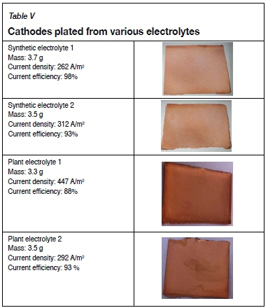
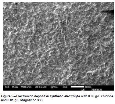
Synthetic electrolyte 1, containing 0.025 g/L chloride and 0.01 g/L Magnafloc 333, produced a deposit that was quite compact and dense. SEM images showed mostly polyhedral crystals, with sharp edges and flat, smooth surfaces. Very few spherical nodules were noticed. Synthetic electrolyte 2, containing 0.03 g/L chloride and 0.01 g/L Magnafloc 333, gave a very similar good-quality deposit, with some spherical nodules visible, as shown in Figure 5. Both deposits were fairly level, but with visible cracks and pores. The cracks possibly indicate stress in the deposits. Copper deposits electrowon in the presence of polyacrylamides were found by Coetzee (2018) to exhibit cracks in certain cases. Fewer pores were seen at the higher chloride level.
For plant electrolyte 1, containing 0.031 g/L chloride and 0.01 g/L Magnafloc 333, there were many spherical nodules visible, with much void space and cracks between them. The nodules were generally between 50 and 100 μm in diameter. Void space is undesirable, because electrolyte would be trapped in the deposit, lowering its quality. The nodules had very rough surfaces. In general, the deposit was rougher and darker in colour than those from the synthetic electrolytes.
A much more compact surface was produced from plant electrolyte 2, which contained double the amount of smoothing additive at 0.02 g/L Magnafloc 333. The spherical nodules present had an average size of 50 to 80 μm The nodules still had rough surfaces and pores and cracks were visible in the deposit, as shown in Figures 6 and 7.
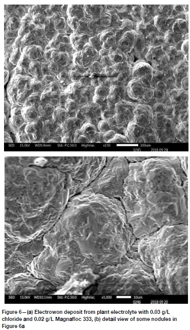
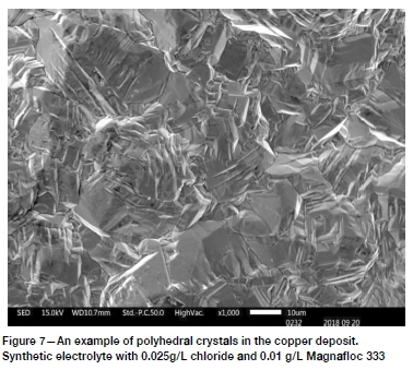
It is concluded from the evidence presented here that surfaces with many spherical nodules tended to be rough in appearance, while surfaces with more polyhedral crystals tended to be smooth. An example of the latter is shown in Figure 7.
The plant electrolytes produced visibly poorer quality deposits than the synthetic electrolytes, even at higher Magnafloc 333 levels. This is probably associated with higher levels of contamination, which could be partly inorganic; however, these electrolytes were stripping solutions from solvent extraction and likely contained dissolved, and possibly entrained, organic extractant and diluent. This type of contamination is known to be generally deleterious to cathode quality (Sole and Tinkler, 2016). The level of contamination probably also explains why the deposits obtained in the electrowinning experiments were coarser than those seen on the Hull cell cathodes.
Conclusions
Hull cell tests in various electrolytes showed the optimum concentrations of chloride and Magnafloc 333 to be 0.025 g/L and 0.01 g/L, respectively, in a current density range of 350400 A/m2. This result was confirmed by longer-term electrowinning tests in similar synthetic electrolytes. However, the plant electrolytes produced noticeably poorer deposits. This is likely due to organic entrainment from the preceding solvent extraction section. A higher level of Magnafloc 333 (0.02 g/L) improved the quality of the deposit. The surface obtained at 0.01 g/L Magnafloc was found to be very porous and rough, which would result in entrapped electrolyte and thus poor cathode quality. Surfaces with many spherical nodules tended to be rough in appearance, while surfaces with more polyhedral crystals tended to be smooth. All deposits obtained in the electrowinning tests had cracks, which became worse with increased levels of additives.
Acknowledgements
The Namibia University of Science and Technology is thanked for financial assistance and permission to publish this work. Professor Sofya Mitropolskaya is thanked for her contributions regarding the interpretation of results.
References
Beukes, N. and Badenhorst, J. 2009. Copper electrowinning: theoretical and practical design. Journal of the Southern African Institute of Mining and Metallurgy, vol. 106, no. 6. pp. 343-356. [ Links ]
Caulfield, M.J., Qaio, G.G., and Solomon, D.H. 2002. Some aspects of the properties and degradation of polyacrylamides. Chemical Reviews, vol. 102, no. 9. pp. 3067-3083. [ Links ]
Coetzee, C. 2018. Characterizing the role of polyacrylamide additives in copper electrowinning MEng thesis, University of Stellenbosch, South Africa. [ Links ]
Cui, W. 2014. Effect and interactions of commercial additives and chloride ion in copper electrowinning. MS thesis, Faculty of Materials Science and Engineering, Missouri University of Science and Technology, Rolla, MO. [ Links ]
Davenport, W.G., King, M., Schlesinger, M., and Biswas, A.K. 2011. Extractive Metallurgy of Copper. 4th edn. Pergamon, Amsterdam. [ Links ]
Fabian, C., Ridd, M.J., and Sheehan, M. 2006. Rotating cylinder electrode study of the effect of activated polyacrylamide on surface roughness of electrodeposited copper. Hydrometallurgy, vol. 84, no. 3-4. pp. 256-263. [ Links ]
Gabe, D.R. 2007. Hull and his cell. Transactions of the Institute of Metal Finishing, vol. 85, no. 6. pp. 285-286. [ Links ]
Institute for Interconnecting and Packaging Electronic Circuits. 1997. Plating quality Hull cell method. Northbrook, IL. [ Links ]
Mirza, A., Burr, M., Ellis, T., Evans, D., Kakengela, D., Webb, L., Gagnon, J., Leclercq, f., and Johnston, A. 2016. Corrosion of lead anodes in base metals electrowinning. Journal of the Southern African Institute of Mining and Metallurgy, vol. 116, no. 6. pp. 533-538. [ Links ]
Muresan, L., Varvara, S., Maurin, G., and Dorneanu, S. 2000. The effect of some additives upon copper electrowinning from sulphate electrolytes. Hydrometallurgy, vol. 54, no. 2-3. pp 161-169. [ Links ]
Nikoloski, A. and Nicol, M. 2008. Effect of cobalt ions on the performance of lead anodes used for the electrowinning of copper - a literature review. Mineral Processing and Extractive Metallurgy Review, vol. 29, no. 2. pp. 143-172 [ Links ]
Pletcher, D. and Walsh, F.C. 1993. Industrial Electrochemistry. Springer, The Netherlands. [ Links ]
Robinson, T.G., Sole, K.C., Sandoval, S., Moats, M., Siegmund, A., and Davenport, W.E. 2013. Copper electrowinning - 2013 world operating tankhouse data. Proceedings of Copper-Cobre 2013, vol. V. Gecamin, Santiago, Chile, pp. 3-14. [ Links ]
Sole, K.C. and Tinkler, O.S. 2016 Copper solvent extraction: status, operating practices, and challenges in the African Copperbelt. Journal of the Southern African Institute of Mining and Metallurgy, vol. 116, no. 6. pp. 553-560. [ Links ]
Winand, R. 1992. Electrocrystallization - theory and applications. Hydrometallurgy, vol. 29. no. 1-3. pp. 567-598. [ Links ]
 Correspondence:
J.C. Jacobs
Email: jorienjacobs@gmail.com
Received: 25 Mar. 2019
Revised: 22 Jul. 2019
Accepted: 10 Oct. 2019
Published: November 2019

