


Services on Demand
Article
 English (pdf)
 Article in xml format
 Article references
Indicators

Related links
-
 Cited by Google
 -
 Similars in Google
Share

 Permalink
Journal of the Southern African Institute of Mining and Metallurgy
On-line version ISSN 2411-9717
Print version ISSN 2225-6253
J. S. Afr. Inst. Min. Metall. vol.119 n.10 Johannesburg Oct. 2019
http://dx.doi.org/10.17159/2411-9717233/2019
GENERAL PAPERS
The impact of forensic laser scanning technology on incident investigations in the mining industry
R. Webber-YoungmanI; H. GroblerII; T. GaziI; F. StrohIII; A. van der VyverIV
IUniversity of Pretoria, South Africa
IIUniversity of Johannesburg, South Africa
IIIHorts Geo Solutions, Cape Town, South Africa
IVSherisk, South Africa
SYNOPSIS
Risk assessments have been conducted in the South African mining industry over the past 20 years, but still we do not always correctly identify the root cause of an incident. An incident investigation is not only about identification of the hazards, but also about understanding the way hazards materialize and what the release mechanisms are. Fundamentally, risk is about uncertainty and for this reason incident investigations remain a very subjective practice. In addition, the low level of detail obtained by conventional surveying is not appropriate in the changing world of technology and data availability. However, a significant improvement in risk management has been shown where mines have adopted the principle of multilateral hazard identification through the inclusion of laser scanning, along with multiple control regimes to avoid repeats of incidents. This article provides an outline and description of the mines' accident investigation process from the time an incident occurs to the point when the investigation is closed out. It also examines how laser scanning can be used to add significant value in terms of identifying the real or root cause of an incident and in this way allow real working solutions to be formulated to avoid incident repeats. What has been learned from laser scans of a number of incidents is discussed. The article highlights the requirements for forensic surveying specifically in an underground environment and alerts the reader to pitfalls and potential flaws that can be introduced into a forensic survey if correct attention is not given to fundamental surveying principles.
Keywords: laser scanning, virtual reality, incident investigation, forensic surveying, interactive safety training, risk management.
Background
In the South African mining industry, great emphasis is placed on creating a safe, healthy, and productive working environment. Fatalities have a major impact on the perception of mining as a career and are detrimental to the image of the industry as a good and safe working environment. All mining companies have embarked on focused risk management programmes. The occurrence of serious incidents and related fatalities is, however, still unacceptably high, and more emphasis should be placed on strategies in order to be able to achieve the 'zero harm' goal adopted by all South African mines. History has proved that fatalities are 'cyclical' in nature. Bad periods are often followed by good periods due to the subsequent intense attention to improving adherence to standards. However, the aim is to minimize these cycles and pursue a real drive towards zero harm. Here, the use of laser technology in incident investigations can play a significant role.
Good risk management practice and mine health and safety legislation place an obligation on mine operators to investigate injury incidents with a view to learning from control failures and continuously improving conditions at mine sites. Different companies have developed in-house policies and procedures to provide guidance to their personnel on what to do when an incident occurs in the workplace, and how to handle the site, the investigation, and its outcomes. In general, the aim of the procedures is to ensure compliance with the law, communicate incidents, and align with the principles of consistency and transparency on a risk-related basis.
Forensic surveying of mine incidents has always been the responsibility of the mine surveyor. Such forensic surveying is still a combination of traditional traversing methods and tape surveying. Traditional surveying methods, photographs, videos, incident reconstruction simulations, and advanced scanning are used to document and reconstruct an incident, detailing risk in real time and simplifying the process of risk analysis. The outcome of the latter provides risk levels dependent on the effectiveness of critical controls captured in real time. However, the traditional surveying methods often cannot do justice to the full 3D domain in which the incident took place, and furthermore they expose the survey crew to the high-risk environment that contributed to the incident in the first place. Through the years many incidents have occurred where the outcome was, for example, assigned to failure to recognize the hazard, inappropriate behaviour, risk management systems that failed, and many more. Over the past 20 years we have been doing risk assessments in the South African mining industry, and still we do not always correctly identify the root cause of an incident. The low level of detail obtained by conventional surveying is no longer appropriate in the changing world of technology and data availability.
Laser scanning for forensic analysis of road accidents and crime scenes has been developed to such an extent that evidence obtained through this method is expected and required for any formal investigation process. In the mining industry, laser scanning has at last been adopted for day-to-day activities, and new applications for scanning data are developed on an almost daily basis. A significant improvement in risk management has been shown where mines have adopted the principle of multilateral hazard identification through the inclusion of laser scanning, along with multiple control regimes, to avoid repeats of incidents. Laser scanning provides an accurate, unambiguous picture of a defined area of the mine. Aftermath scenarios set forth in a 'bow tie analysis' support the fact that the laser scanning process will serve as a silent visual witness to any near-miss event, deteriorating condition, or lack of critical control systems. Persons involved in control analysis are more alert to observing control breakdown mechanisms. Real-time laser scanning will further enhance the decision-making process, resulting in a more robust and well-defined judgement relating to the incident.
Accident/incident classifications
Incidents are classified as either reportable or non-reportable, and can be further defined as minor or major incidents. These classifications are important in the sense that resource mobilization to handle any incident depends on how it is classified. This varied treatment of incidents, depending on whether they are minor or major, reportable or non-reportable, is pervasive throughout all the reviewed mine procedures.
A major incident is a significant event which demands a response beyond the routine. Significance is determined by the severity of the incident, the potential degree of public concern, and the nature and extent of previous such incidents. Any incident that has led to the death of an employee or a contractor's employee, or that has caused a serious threat to the health of any employee which could result in death, will fall into this category. This definition is an indication of why the incidents are treated differently.
Objectives relating to incident investigations
The collection of accurate information about what occurred, when, and where, is essential to ensure a comprehensive and reliable analysis of a major incident or, for that matter, any reportable incident. In the context of incident investigations, there are several specific rules to be followed in the collection of evidence and information about the incident. They are as follows:
> Act timeously. Information decays rapidly with time and needs to be preserved before people forget what happened.
> Preserve evidence; do not change or tamper with any evidence. Photographic records are an essential aid to record all aspects of the scene and the surroundings.
> Be factual and avoid all conjecture, particularly about the sequence of events that led to the incident. There can be a great temptation to make the evidence fit a pattern or a preconceived situation or cause.
The accident/incident investigation process flow
Subsequent to a careful review of the accident investigation procedures from the platinum and gold mining industries, one can say that the activities shown in Figure 1 invariably define the basic process of an incident investigation that is followed until the corrective action(s) have been implemented.
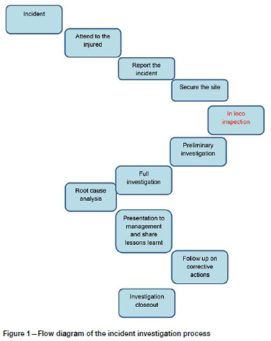
The processes indicated in Figure 1 can be elaborated as follows (in this case the example relates to an underground incident):
A. Incident-An injury or damage to property occurs.
B. Attend to the injured-Assuming that employee is injured, first aid may have to be administered and the injured may have to be removed from danger. Identify witnesses to the incident.
C. Report the incident-The supervisor has to report the incident to the banksman, who will inform management and arrange for the injured person to be transported to surface in the case of an underground working. A report must be made to the Department of Mineral Resources (DMR) if it is a reportable incident.
D. Secure the site-The site of the incident must not be disturbed, as per regulations, unless it is necessary to secure the site to avoid further injuries. This disturbance of the site must be authorized by the manager of the site with the agreement of the mine inspectorate.
E. In-loco inspection-The site must be inspected soon after the incident. Line supervision will be present, together with employee representatives and the safety officer of the workplace. The injured employee may nominate a fellow employee to represent them at the in-loco inspection. This is a crucial time when evidence is collected. The following evidence is normally collected:
• Process evidence
• People evidence (witness statements)
• Paper evidence
• Equipment evidence
• Photographic evidence.
Photographs and measurements should be taken showing the distance between the location of the incident and all surrounding items, equipment structures, activities, and people. These measurements should be superimposed on copies of the photographs or on drawings. Other lengths, widths, and dimensions may also be taken. The reason why the in-loco part of the process is highlighted in Figure 1 is to emphasize the importance of this part of the process in terms of finding the root cause of the incident.
F. Preliminary investigation-This is conducted by the line manager of the workplace concerned. The report should be submitted to the safety department within the stipulated timeframe of a week or so.
G. Full investigation-This is conducted by experts appointed by the safety department together with the executive responsible for the area where the accident occurred. The investigation should be finalized within a week or so.
H. Root cause analysis-Any of the techniques, for example the '5 Why Analysis' or 'Fault Tree Analysis', may be applied to get to the real causes of the incident. It is at this stage that the photographic images taken of the site with marked locations of witnesses become important. A comment on root cause techniques is that one should use what is appropriate for the type of incident being investigated and should document the root causes and their controls.
I. Presentation to management and lessons learnt-The findings must be discussed with management and control improvements or new controls recommended to avoid the re-occurrence of a similar incident. Through newsflash or other means, what has been learnt from the incident must be distributed to all relevant employees. Lesson learned could also be incorporated into work procedures, training manuals, and the induction of new employees.
J. Follow-up on corrective actions-The safety officer of the area must then follow-up on the corrective actions to determine whether they have been adequately implemented before closeout of the investigation.
K. Investigation closeout-Once all the corrective actions have been implemented and this has been confirmed through inspection by the safety officer, the investigation may be marked as completed.
Legislative requirements pertaining to incident investigations
In terms of legislation, there are several requirements that need to be complied with, but it is not the intention to repeat them here; it is assumed that all legislative requirements are met. The purpose of this article is to expand on the significance of scanning in supplementing adherence to the legislative requirements. It must, however, be stated that the following dangerous occurrences/ incidents and related consequences must be investigated and reported to the Principal Inspector of Mines:
> Rockbursts and falls of ground
> Caving
> Flow of broken rock
> Breakdown of main ventilation fan
> Power failures
> Fires and explosions
> Flammable gas exceeding standard
> Winding plant incidents
> Lift and elevator incidents
> Objects falling down shafts
> Emergency or rescue procedures
> Self-propelled mobile machinery incidents
> Boiler and pressure vessel incidents
> Chairlift incidents
> Explosives incidents.
Although mines have fairly well-developed procedures to guide personnel in case of an accident, the procedures reviewed above do not go into detail about the collection of evidence, other than mentioning it. The involvement of mine surveyors is required in all incident investigations so as to take measurements and identify locations accurately. Leaving aside all the current requirements, the main aim of this article is therefore to expand on laser scanning and the potentially significant contribution that it can make to the incident investigation process.
Challenges associated with measuring during in-loco incident investigations
When conventional measuring techniques are used, what needs to be measured at the scene of the incident is often left to the interpretation of the scene investigator (normally the Inspector of Mines). The findings are then turned over to the mine surveyor who must interpret the required perspective views when measuring the scene. This method leaves itself open to mistakes, as critical information pertaining to the incident may be overlooked or missed.
In the subsequent investigations, the mine surveyor may then be required to explain why a specific feature critical to the investigation was not measured and provide an explanation as to why it was indicated in a specific manner on the plan, section, or perspective drawing of the incident. All measurements, however professionally executed, are dependent on the objectivity and, to a large extent, the experience of the mine surveyor. The frustration of all incident investigation surveyors is well summed up in the following statement: we first interpreted what we wanted to measure, and that interpretation was often challenged. Then we were challenged on how we measured it. And then we got challenged on how we took the measurements for our demonstrative data' (Reuschling, 2014).
Infrastructure scanning is a tool to be used in mitigating risk and preventing loss of life. With an incident investigation, the person normally involved and asked about the accessibility and layout of an area is the person who works in that area. However, if that person is not available, critical information can be lost or neglected. In the case where this person is involved in the incident scene or is one of the victims, the problem is further compounded. According to De Leeuw and Hahnel (2015) 'Interactive software gives users the ability not only to explore the scene, but also to pan, zoom, measure, mark-up and hyperlink data'. This helps to avoid personal mistakes and/ or misinterpretations by specific individuals involved in the investigation.
Conventional forensic measuring process
In its most basic state, the process of measuring at a lost-time or fatal incident is initiated as soon as the initial recovery process begins. In instances where the victim can be recovered safely without the assistance of a rescue team, the mine surveyor will become involved only at a later stage. Where a rescue or recovery process must be initiated by a mine's rescue service unit, the mine surveyor will provide rescue plans and detailed plans for the area. In the event of a major incident and recovery operation, the Inspector of Mines (IOM) is notified. At the earliest possible time, an in-loco inspection of the undisturbed incident scene is arranged.
During this in-loco inspection, the Inspector of Mines, the mine manager, production members, union representatives, and the mine surveyor visit the scene. After the initial in-loco interviews, the Inspector then requests the surveyor to 'pick up' specific features, including the position of the victim(s) and important features, and indicate specific section views. This is then left to the mine surveyor to execute. Measurements can take hours, depending on the level of detail required and the complexity of the incident. Once these have been completed, the mine surveyor presents an incident plan, which consists of a title block, a plan view, and one or more section views. This is normally labelled 'Exhibit B' for the official investigation. In relation to incident measurements that have been done in 2D in the past, the following shortfalls have been identified:
> The mine surveyor is exposed, with the crew, to the same factors that led to the original incident, while secondary failures may occur (Borman, 2006)
> Time-critical tacheometry, supplemented by tape surveys and photographs, takes time
> There is personal perspective and interpretation
> Information can be manipulated
> Incorrect bookings and observations will cause major errors in interpretation
> Section drawings are limited and do not provide sufficient detail of the scene
> Critical information can be missed
> The sensitive nature of some issues, such as tribal traditions that require a ceremony to be completed wherein the 'victim's soul is recovered and taken home', can lead to time being lost with regard to completing the investigation.
From the above, it is obvious that accuracy and attention to detail are critical when recording specifics relating to the incident. It is also clear that because of the dependence on human input and influence, experience, and a critical eye are needed in all aspects. This is where failure sometimes occurs and where laser scanning can play a significant role in future.
How does laser technology work?
Light detection and ranging (LIDAR) or 'laser scanning' uses a narrow laser beam to map physical features to a high degree of accuracy. Laser scanners are used to rapidly measure a high density of distances to objects. During the laser measurement, the horizontal and vertical angles are reduced with the range measurement to generate a point. Additional information concerning the point - reflectivity, high-definition (HD) colour, and in some cases thermal information - is simultaneously encoded into each point.
The resultant collection of points, each of which has a unique x, y, and z coordinate relative to the laser scanner, is referred to as a 'point cloud'. The strength of the return beam reflected from an object will depend on the surface texture and reflectivity of the object. The reflection coefficient of the laser beam can be analysed for multispectral-like characteristics of the object not observable by the naked eye. Some instruments are able to make more than a million observations per second, depending on the recommended range, accuracy, and computational power of the instrument. The accuracy of laser scanners is, in most cases, within 1 mm at close range, although this is dependent on the measurement type and range of the specific instrument (Colombo and Marana, 2010). The accuracy of laser scanning can be influenced by wet surfaces and highly absorbent features such as coal seams.
The main advantage of an accurate point cloud is that distances can be measured between any of the objects (points) scanned (x, y, and z coordinates are recorded with the scan). Several other advantages of laser scanning have been identified as follows:
> Laser scanning on its own does not require illumination to take measurements and can therefore be used in poor lighting conditions.
> Laser scanning measurement does not require physical contact with the objects surveyed, and the scanning of an object will not affect the stability or integrity of an object.
> With laser scanning, 'noise', such as dust, moving vehicles or people. and vegetation, can be removed from the point cloud. In a complex multilevel and poorly illuminated environment, this capability provides a powerful tool for planning and monitoring purposes.
> A laser scanner can also be mounted on an aircraft (airborne), on a drone or on a vehicle (mobile), in a backpack, or used as a conventional survey instrument on a tripod, when this is also referred to as terrestrial laser scanning.
Current developments in laser scanning technology
Applications of laser scanning are in an advanced stage and in a constant state of innovation. The combination of traditional photogrammetry and laser scanning has enabled a number of new applications. Simultaneous localization and mapping (SLAM) algorithms allow one to keep track of observers' or agents' locations in an unknown area while constructing and updating a map of that area (Kleiner and Dornhege, 2016). A combination of laser imagery and indoor beacons and a geographic information system (GIS) is now enabling real-time indoor navigation. This technology has been introduced at Schiphol Airport in the Netherlands, and allows passengers to use a simple app on their phones to navigate in the airport (Smolders and Görtz, 2016). This application makes building information management (BIM) and true indoor navigation possible.
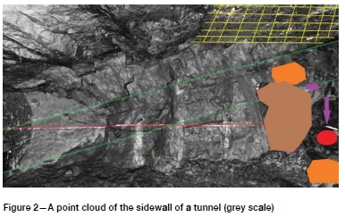
The widespread reduction in hardware and battery size is allowing the development of laser scanners that can be mounted on remotely piloted aerial system (RPAS) platforms; a number of these RPAS systems have become available in the past year. A hybrid of standard total station and laser scanning provides an accurate, spatially referenced platform for scanning objects and transitioning to staking and positioning of points relative to the point cloud. With this hybrid instrument, objects or structures that have been identified in the point cloud can be marked out and located. Figure 2 shows an example of a point cloud of a sidewall of a tunnel underground, with its related geological features drawn in afterwards. This was possible as a result of the detail provided by the point cloud.
The evolution of laser scanning technology is currently taking place in the field of 'wearable scanners'. A handheld scanning system has been available for some years and used with varying degrees of success. In areas where a GPS (or GNSS) signal is not available, LIDAR imagery is 'cut up' into segments and compared with match overlaps in order to build an image. In areas where there are only small changes in the dimensions of the environment in which the observer moves (such as a long, straight concrete passage), the accuracy of the final image may be adversely affected.
A laser scanner in a backpack allows the observer to walk through an area unhindered while at the same time logging accurate data in a fully 3D environment. Wearable technology will have applications in industrial emergency response training, documentation of routes, natural disaster response, and terrain assessment. Currently, one new backpack innovation combines five cameras with a LIDAR profiler, and provides an accuracy of 3 cm in a 3D image (Woods, 2016).
Laser scanners with reflective index images, colour point clouds and animation
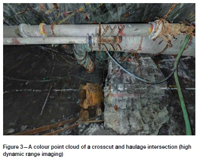
Most modern 3D laser scanners are equipped with HD cameras that take a panoramic 360° image at each set-up. The colour pixels of the panoramic image can then be assigned to the correlated points in the point cloud to produce a true-to-life 3D colour point cloud. High dynamic range imaging (HDRi) is commonly known as 'bracketing' in single lens reflex (SLR) cameras. LED lighting built into the latest scanners has revolutionized the technology by enabling one to take images in dark spaces. Before the introduction of this latest camera technology into scanners, reflective index images were preferred due to over- and underexposed images. Figure 3 shows a crosscut and haulage apex image in which this new-technology scanner was used.
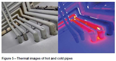
Other laser scanning technologies - thermal imaging
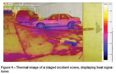
For now, this camera technology is not built into scanners but added on top of the scanner, and allows for an additional spectrum in imaging that can be mapped onto the point cloud. This technology has created renewed interest in the forensic community with its ability to record data beyond the visible spectrum, with specific reference to heat sensing. Figure 4 shows a scanned image of heat signatures relating to a staged incident. Figure 5 shows an example of a thermal scan indicating hot and cold areas in pipes.
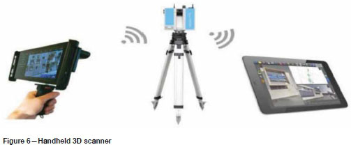
Handheld 3D scanner
Although this 3D scanner is not strictly speaking a laser scanner, but commonly known as a structured light scanner (SLS), it operates in the infrared spectrum in combination with a stereo camera. Its appeal is in its simplicity of operation and its cost. The value as an additional tool in the forensic box lies in how it is now utilized as an infill in conjunction with the real-time scanners. An example is shown in Figure 6.
Real-time scanning (RTS)
Laser scanning for forensic analysis of road accidents and crime scenes has been developed for use in cases where such evidence is expected and required for any formal investigation process. In the mining industry, laser scanning has now been adopted for day-to-day activities in many mines, and new applications for scanning data are developed on an almost daily basis.
Until very recently, scanning was performed through postprocessing. This means that the results from scans were only combined and visualized in the survey office. Often, critical areas of the scene were not covered, only to be discovered later when it was not possible to return to the scene. With the addition of tracking sensors onboard the scanner, coupled with Wi-Fi and a handheld computer (such as an Android Tablet), RTS is now possible. As the operator moves from set-up to set-up, the data is fed via Wi-Fi to the tablet where set-ups are registered together and displayed in real time.
Laser scanning techniques are therefore able to reduce the time during which the survey crew is exposed, while being able to take a complete 3D snapshot of the incident scene in a low-visibility environment. The data-set produced by a laser scan can be used to develop various points of view of the incident, and allows the data to be visualized in its original context.
Other advantages of laser scanning
Mine surveyors, as mentioned before, are tasked with the mapping and recording of all significant injury and fatal injury scenes in the mining industry. Laser scanning is being increasingly used in this application as the laser spectrum can sometimes identify causes that cannot be seen with the naked eye. The application of post-incident scanning and scanning for structure monitoring for the prevention of future incidents is well established.
This technology can, however, also be applied to provide first-responders with a valuable tool for understanding the environment in which a rescue operation must be performed. The advantage of a scanning device on a mobile platform is that an incident scene can be surveyed and mapped in a short time by the initial response team. Such a preliminary map of the incident can assist rescue personnel in forming a better impression of the incident scene and surroundings. In a complex rescue scenario, a 3D image could provide response teams with a better understanding of the positions of victims and the safety conditions on site before actual rescue operations start. Such information can be used to plan access routes, identify areas to be avoided and, with subsequent scans, may be able to monitor structure movement.
Laser scanning incident case study
An employee was killed by a rockfall-related incident in a development end in a mine in South Africa. At the scene of the incident, the origin of the rock that caused the incident could not be identified. Laser scanning was used to scan the whole area of the incident within approximately 40 minutes. The incident scene was recorded through four set-ups that covered the full scene of the incident, including an area towards the waiting place of the development end. Through an analysis of the scan data, the origin of the rock and the reason for the fatality were clearly established, demonstrating the importance of laser scanning in clearly recording all related information pertaining to the incident. Other knowledge gained from this and other incidents can be summarized as follows (Reuschling, 2014):
> Scanning equipment allows remote access to unsafe areas.
> Scanning is fast and enables the scene to be cleared faster.
> The scanners capture all detail, reducing queries and capturing information that may only later prove its importance. This is because the point cloud captures everything and from all perspectives.
> Scanning provides accurate, unbiased data relating to everything on scene at that specific time.
Further advantages are as follows:
> The surveyor can now produce the facts exactly as they are for interpretation by the investigation team.
> As the scans are displayed in 3D, they can be rotated and viewed from any angle so as to simplify understanding of the activities associated with the incident.
> The scans allow all the members of the investigation team to have the same understanding of the environment in which the incident took place.
> The scans facilitate a potential reconstruction of the incident environment using real data as obtained from the scanner as opposed to assumed correct data from other measuring and position specifics.
> Where needed, these 3D images of the incident can be used to enhance understanding of the incident by the inclusion of simulations within the 3D space.
Risk management practices and laser scanning
Accident theories have evolved over the years, but their driving force can still be summed up in the words of E.I. Du Pont (17721834): 'We must seek to understand the hazards we live with.' Heinrich (1931) documented the first scientific method of injury prevention and the effects of accidental injury causation. Unfortunately, this was based purely on insurance claims, and for that reason his method of data gathering also initiated the theory that the characteristics of individuals and their behaviour are the root cause of most accidents.
In 1961, during the same period in which most of the risk analysis techniques were developed, Gibson postulated that 'man and machine and/or energy' co-exist and do not act independently, reasoning that specific engineering design barriers may alleviate cognitive human weakness and overcome the problems of the Heinrich model (Gibson, 1961).
Viner (1991) developed the energy damage model and advocated this problematic engineering approach since it places the focus on the pre-event energy-control stage, before the loss of control causes the harmful energy to be transferred to a person or asset. The chief objective would be to eliminate or reduce the latent conditions of the unsafe person while he or she is operating in an unsafe place. James Reason (1997) documented a non-scientific approach, referred to as the 'Swiss cheese' method, which identifies human error, but more as a consequence than a cause.
The history of accident models from the 1900s to date can be traced through three distinct phases.
> Simple linear models reflecting single root causes that interact sequentially (storyline principles), creating the expectation that accidents can be prevented by the removal of any of these causes, thus breaking the line of events.
> Complex linear models suggesting multiple and latent causes. During this phase the assumption was that the root causes that are the furthest away (organizational) contribute less than the root causes of human behaviour that are directly or indirectly the closest to the accident on the linear line.
> Complex nonlinear models involving a combination of mutually interacting variables occurring in the 'real work environment'. This New Age thinking advocates that only when these variables are identified, analysed, and understood can effective barriers be designed (Hollnagel, 2010).
When we put all of the above theories and models together, we have holistically created mass confusion. At best, Hollnagel created a new way of thinking that allows a constructive approach to proactive event investigations and reactive accident investigations. This opens a new window with multiple dropdown menus (to borrow some terms from computers) for more detailed investigation, in other words, a full life-cycle, stated as follows:
> Pre-condition analysis
> Release mechanism analysis
> Pre-event analysis
> Event analysis (Bow Tie analysis of the top event)
> Outcome analysis (accident investigation)
> Consequence analysis.
Therefore, the important question to ask is: How can this be presented in an acceptable visual format? Over the last 10 years or so, more than 400 Bow Tie analyses have been done from which it was concluded that the majority of 'scenario events' were a direct result of poor design. This conclusion leads to three basic questions (in the context of the new way of thinking).
> What is (are) the real reason(s) preventing us from creating visual designs for mining projects?
> What is (are) the real reason(s) preventing us from using real-time scanning (RTS) of the disturbed environment or underground excavations?
> What is (are) the real reason(s) for not having RTS available immediately after an unwanted event?
For some time, RTS has been regarded as an after-event 'instrument' to assist managers in understanding the conditions under which the event took place, but since laser scanning technology is already used for forensic surveys and data collection, we now have the opportunity to utilize it in a proactive manner. Preventing accidents or their re-occurrence involves an understanding of the preconditions mentioned earlier. Having information about the full life-cycle of the hazard available will reveal not only the unwanted 'energy flow', but all mechanisms that contributed to the event. Barrier design can be simulated and its effectiveness visually determined.
With the exception of a few mines, critical control management, which derives from the Bow Tie analysis program, has been implemented in our industry. There is a 'perception' that implies by default that a vast improvement of control effectiveness would be evident from such management. This is, however, nothing other than a numbers game. We have only two options for indicating an improvement in the effectiveness of control:
> Quantitative analysis of new barrier designs
> Laser scanning and forensic analysis of the implementation of new controls.
Clearly, incident investigations will not solve the lack of ability to improve our incident statistics. We will have to adopt a more realistic approach and align our systems to focus more on the pre-event conditions and release mechanisms. Laser scanning during the early stages of design projects, or during proactive mapping of critical areas of a mine, will provide us with the necessary abilities to foresee events, including possible 'black swan' events. This will facilitate preparing for these events by making the necessary capital investment to cater for change or redundancy within design barriers and, lastly, improve the human capital of the workers who may possibly be exposed to such conditions.
Risks and other characteristics associated with laser scanning
Currently, there is no one scanner that fits all applications, and attention should be given to the deliverables and the accuracies needed for analysis when choosing the scanner to be used. The Class 1 laser that is used in most commercial laser scanners is eye-safe in all conditions. Care should be taken when using Class 3R lasers, which can be dangerous if exposed for extended periods of time. It must be noted that although phase-based scanners are extremely accurate within the first 10 to 20 m (typically to within 1-2 mm), the accuracy degradation is hyperbolic. This causes a problem if a cloud-to-cloud-only registration strategy is adopted, as most of the common registration data falls in the 20 m plus range where data is thinning.
It remains good practice to add some targets as we generally need to georeference the point cloud to the mine coordinate system to make comparisons with historical surveys of the area. Registering with only a consecutive strategy can result in the accumulation of errors from scan to scan, but adopting a network calculation strategy achieves not only good relative accuracy, but also absolute accuracy over the entire scene.
Further care should be taken when scanning scenes with elements of extremely high reflectivity, such as shiny metal surfaces. The same problems of accuracy uncertainty are experienced at extremely low reflectivity, such as when scanning coal. Scanning data from areas with wet surfaces needs to be managed well when the data is being processed because a wet surface creates a mirror effect, with the laser reflecting off the wet surface. This results in false points below the actual surface, referred to as 'ghosting'. Materials with the ability to absorb the laser beam partially before reflecting it back to the scanner remain troublesome and difficult to detect. These include marble, polypropylene, and Styrofoam.
Conclusions
From this article the following observations can be made:
> 2D surveying of incidents has added value in the past and still has a role to play, but is outperformed by the additional benefits that 3D laser scanning brings.
> Incident investigation in the South African mining industry is a rigorous process, and 3D laser scanning already makes a significant contribution to the recording of data from incidents and the preventative measures related to them.
> The 3D laser scanning of mine fatality scenes has set a new standard for capturing the details of the incident scene.
> Although 3D laser scanning has not yet replaced the traditional 2D incident plan, it currently complements this plan with a 3D point cloud that is much richer in information and easier to interpret by non-technical people, if need be.
> Furthermore, 3D fly-through (3D video) of the scene results in a much easier comprehension of the circumstances and facts at hand.
Suggestions for further work
Based on the laser scanning work that has already been carried out, it is important to construct and/or develop a best practice laser scanning work flow. A laser scanning database needs to be established to take advantage of the additional benefits to be derived from new technology developments. It is also important for scenario scanning to be developed in a virtual reality training environment that is more realistic to help with the prevention of incidents.
Acknowledgements
The authors would like to acknowledge and thank the mining industry in general for accepting this new technology in view of the value of its application and its potential role in preventing further incidents. In addition, we wish to thank all the authors who contributed to the writing of this article, as well as Mr Donovan Anderson, formerly of Anglo American, who made valuable scanning information and visuals available.
References
Borman, D. 2006. Underground mine profiling. Proceedings of the Second International Platinum Conference, 'Platinum Surges Ahead. Symposium Series S45. Southern African Institute of Mining and Metallurgy, Johannesburg. pp. 165-168. [ Links ]
Colombo, L. and Marana, B. 2010. Terrestrial laser scanning. GIM International, 3 December 2010. http://www.gim-international.com/content/article/terrestrial-laser-scanning-2 [accessed 30 May 2018]. [ Links ]
De Leeüw, D. and Hahnel, F. 2015. Is laser scan data part of your incident training and response? Leica Geosystems. http://psg.leica-geosystems.us/page/is-laser-scan-data-part-of-your-incident-training-and-response [accessed 5 May 2016]. [ Links ]
Gibson, J.J. 1961. The contribution of experimental psychology to the formulation of the problem of safety - A brief for basic research. Behavioural Approaches to Accident Research, vol. 1, no. 61. pp. 77-89. [ Links ]
Heinrich, H.W. 1931. Industrial Accident Prevention: A Scientific Approach. McGraw-Hill, New York. [ Links ]
Hollnagel, Ε. 2010. FRAM background. http://sites.google.com/site/erikhollnagel2/coursematerials/FRAM_background.pdf [accessed 15 June 2017]. [ Links ]
Kleiner, A. and Dornhege, C. 2011. Mapping for the support of first responders in critical domains. Journal of Intelligent & Robotic Systems, vol. 64, no. 1. pp. 7-31. [ Links ]
Reason, J.T. 1997. Managing the Risks of Organisational Accidents. Ashgate, Aldershot, UK. [ Links ]
Reuschling, G. 2014. Four ways laser scanning benefits accident reconstruction. Leica Geosystems, 18 August 2014. http://psg.leica-geosystems.us/page/four-ways-laser-scanning-benefits-accident-reconstruction [accessed 24 June 2017]. [ Links ]
Smolders, M. and Görtz, Η. 2016. Indoor wayfinding at Amsterdam Airport. GIM International, March. pp. 16-18. [ Links ]
Viner, D. 1991. Accident analysis and Risk Control. Derek Viner, Melbourne, Australia. [ Links ]
Woods, S. 2016. Laser scanning on the go. GIM International, March 2016. pp. 29-31. [ Links ] ♦
 Correspondence:
R. Webber-Youngman
ronny.webber@up.ac.za
Received: 24 Jul. 2018
Revised: 13 May 2019
Accepted: 17 May 2019
Published: October 2019

