


Services on Demand
Article
 English (pdf)
 Article in xml format
 Article references
Indicators

Related links
-
 Cited by Google
 -
 Similars in Google
Share

 Permalink
Journal of the Southern African Institute of Mining and Metallurgy
On-line version ISSN 2411-9717
Print version ISSN 2225-6253
J. S. Afr. Inst. Min. Metall. vol.119 n.7 Johannesburg Jul. 2019
http://dx.doi.org/10.17159/2411-9717/244/2019
PAPERS OF GENERAL INTEREST
The effects of froth depth and impeller speed on gas dispersion properties and metallurgical performance of an industrial self-aerated flotation machine
H. NaghaviI; A. DehghaniI; M. KarimiII
IMining and Metallurgical Engineering Department, Yazd University, Yazd, Iran
IIDepartment of Chemistry and Chemical Engineering, Chalmers University of Technology, Sweden
SYNOPSIS
In self-aerated flotation machines, the gas rate depends on operational variables (e.g. froth depth and impeller speed), pulp properties (e.g. solid content and viscosity), and reagent addition (e.g. type and concentration of frother). The gas rate has a strong correlation with the flotation performance by influencing the gas dispersion properties and froth retention time. A factorial experimental design was used to study how the gas dispersion properties, the froth retention time, and the flotation performance respond to changes in froth depth and impeller speed (as the most common operational variables). An in-depth understanding of the effects of impeller speed and froth depth on the gas dispersion properties, especially the bubble surface area flux and froth retention time, is necessary to improve operating strategies for self-aerated flotation machines. All experiments were carried out in a 50 m3 self-aerated flotation cell in an iron ore processing plant. The results showed that the froth depth affected the metallurgical performance mostly via changing the froth retention time. The impeller speed had two important impacts on the metallurgical performance via varying both the froth retention time and the bubble surface area flux in the froth and pulp zones, respectively. The interaction effects of the froth depth and impeller speed were also established. This allowed us to develop a strategy for operating self-aerated flotation machines based on varying the froth depth and impeller speed with regard to the cell duty.
Keywords: self-aerated flotation machine, gas dispersion properties, metallurgical performance, impeller speed, froth depth.
Introduction
A mechanical flotation machine may be divided into two distinct zones. namely the pulp zone and the froth zone (Goodall and O'Connor, 1989; Yianatos, Bergh, and Cortes, 1998; Rahman, Ata, and Jameson, 2015a, 2015b). The overall flotation recovery, Ro, including the true flotation (particles attached to the bubble lamellae) and entrainment (particles recovered in water held in the bubble plateau boundaries), is a function of the recoveries in the two zones. It is calculated as follows (Dobby, 1984):
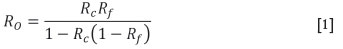
where Rcand Rfare the pulp and froth recoveries, respectively.
A schematic diagram of the pulp and froth recoveries is shown in Figure 1.
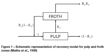
Equation [1] shows that neglecting the recovery in each zone can adversely affect the overall recovery. The froth recovery is primarily a function of the particle residence time in the froth zone (i.e., froth retention time), such that increasing the froth retention time decreases the froth recovery (Mathe et al., 1998). The froth retention time, xfcan be expressed as follows:
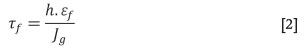
where h. Ef and Jgare froth depth, gas holdup in the froth phase, and superficial gas velocity, respectively (Zheng, Franzidis, and Manlapig, 2004). If the liquid/solids holdup in the froth is negligible (i.e., Ef = 1), then Equation [2] can be simplified to:
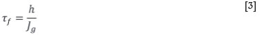
where Jgis defined as the volumetric flow rate of air entering the cell (Qg) divided by the cell cross-sectional area at the pulp-froth interface level (A) (Gorain, Franzidis, and Manlapig, 1997):
The pulp recovery depends on a wide range of complex factors. For instance, the hydrodynamic conditions of a flotation cell are known to directly affect the flotation efficiency. Hydrodynamic parameters, especially gas dispersion properties, are responsible for controlling the particle-bubble contact as an essential part of the flotation process (Schubert and Bischofberger, 1978; Gorain, Franzidis, and Manlapig, 1995a, 1995b). The gas dispersion properties indicate the efficiency of the distribution of air bubbles across the cell volume (Schwarz and Alexander, 2006; Vinnett, Yianatos, and Alvarez, 2014). The bubble surface area flux, Sb, is an efficient measure of the hydrodynamic conditions in a flotation cell, certainly as far as gas dispersion properties are concerned (Gorain, Franzidis, and Manlapig, 1997). The bubble surface area flux is defined as a measure of bubble surface area rate rising through the cell per unit cross-sectional area. It can be described mathematically by Equation [5] (Gorain, Franzidis, and Manlapig, 1997):
where d32represents the Sauter mean bubble diameter.
The bubble surface area flux has a strong correlation with the overall flotation rate constant, k, as shown in Equation [6] (Gorain, Franzidis, and Manlapig, 1999):

where P represents the ore floatability.
This equation implies that the greater the available surface area of bubbles, the greater the chance of particle-bubble contact in the pulp phase. Therefore, it results in a higher flotation rate constant (Gorain, Franzidis, and Manlapig, 1999).
In the flotation process, the gas rate is a key variable which provides the gas surface area required for selective transport of mineral particles (Yianatos, Contreras, and Diaz, 2010). This variable has a positive impact on recoveries of the pulp and froth zones by varying the gas dispersion properties and froth retention time, respectively (Vera, Franzidis, and Manlapig, 1999; Rahman, Ata, and Jameson, 2015a).
In self-aerated flotation machines, the gas rate depends on the pulp properties (e.g. viscosity and solid content), the chemical variables (e.g. type and concentration of frother), and the operational variables (e.g. froth depth and impeller speed) (Yianatos et al., 2001; Girgin et al., 2006). For example, it is increased by increasing the froth depth and the impeller speed. Increasing the impeller speed increases suction, whereas increasing the froth depth reduces back-pressure at the point of gas injection (Girgin et al., 2006). It is obvious that manipulation of the gas rate in self-aerated flotation machines is more complicated than the in forced-aerated flotation machines in which the gas rate is an independent variable.
Froth depth and impeller speed are the most common operational variables in flotation plants and control of them is significant for adjusting the gas rate and improving the flotation performance (Venkatesan, Harris, and Greyling, 2014). Extensive work is reported in the literature on the study of operational variables. These studies generally showed that in pilot and industrial forced-aerated flotation machines, the impeller speed and gas rate have a distinct impact on the bubble size. The bubble size is decreased with increasing impeller speed, and increased with increasing gas rate (Gorain, Franzidis, and Manlapig, 1995a, 1995b; Grau and Heiskanen, 2005; Grau, Nousiainen, and Yanez, 2014). It was found that increasing the impeller speed generally has a positive effect on the rate of flotation, accompanied by a significant decrease in the concentrate grade. This decrease may be due to increases in entrainment or in the rate of flotation of poorly liberated (low grade) particles or floatable gangue (Gorain, Franzidis, and Manlapig, 1997; Deglon, 2005).
Also, it is suggested that the recovery and plant capacity could be increased by manipulating the froth depth and the gas rate, i.e. at a low froth depth and high gas rate, although the concentrate grade could be decreased (Vera, Franzidis, and Manlapig, 1999; Zheng, Johnson, and Franzidis, 2006; Ata and Jameson, 2013; Seguel et al., 2015). Venkatesan, Harris, and Greyling (2014) found a significant interaction effect between gas rate and froth depth, highlighting the importance of testing these factors one at a time in any optimization work.
In recent years, with the growth of flotation control systems, the metallurgical targets of a flotation bank are automatically controlled by manipulating the froth depth, gas rate, and frother dosage, with regard to the monitoring concentrate and tailing grades (Yianatos, Henriquez, and Oroz 2006; Venkatesan, Harris, and Greyling, 2014). Also, the impact of 'gas management' in flotation banks is shown by a number of researchers, in which the gas rate profiling can affect the performance of a flotation bank significantly (Cooper et al., 2004; Hernandez-Aguilar and Reddick, 2007; Smith, Neethling, and Cilliers, 2008; Hadler and Cilliers, 2009; Fournier et al., 2015).
In the published literature, the importance of operational variables such as gas rate, froth depth, and impeller speed in determining the flotation performance has become increasingly recognized. However, the problem at the time is lack of technical and practical details. The effect of operational variables such as impeller speed and froth depth on the gas dispersion properties and froth retention time should be understood. This is a critical requirement for adjusting the gas rate and optimizing the operation in industrial self-aerated flotation cells. For example, it is unclear what happens to the froth retention time as the froth depth increases, because the gas rate and froth depth increase simultaneously while they have a reverse effect and a direct effect on the froth retention time, respectively.
The purpose of this paper is to investigate on the one hand the effects of impeller speed and froth depth on gas dispersion properties and froth retention time, and on the other hand to study the relationship between these parameters and metallurgical performance with the aim of understanding how froth depth and impeller speed affect metallurgical efficiency. This allows us to develop an operating strategy based on the cell duty [e.g. rougher or cleaner) by use of only operational variables.
Materials and methods
Experimental
Industrial-scale experiments were carried out in a 50 m3 self-aerated flotation cell the first cell of the desulphurization flotation bank of the Gol Gohar iron ore processing plant in Sirjan, Iran.
A central composite design (CCD) was used to investigate the effects of impeller speed and froth depth on the process responses (i.e., the gas dispersion parameters, the froth retention time, and the metallurgical efficiency). The CCD is a factorial type of experimental design which enables the investigation of the effects of multiple variables simultaneously. The CCD design has the added benefit of requiring fewer experimental runs (Venkatesan, Harris, and Greyling, 2014).
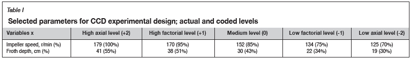
The CCD experiments included 4-factorial, 4-centres, and 4-axial runs. The variable levels are given in Table I. The impeller speed is shown in revolutions per minute (r/min) (and as a percentage of the maximum speed) and the froth depth is shown in centimetres (and as a percentage of the maximum froth depth).
The flotation cell was operated for 20 minutes after changing the operational variables, including the impeller speed and the froth depth. This time is equivalent to three times the pulp residence time that ensures a steady-state operation. The gas dispersion measurements were then carried out along with sampling of the feed, concentrate, and tailings streams. The experiments were conducted based on CCD design and the results were analysed by Design-Expert software version 10.0.6.
Gas dispersion measurements
The gas dispersion properties are usually expressed in terms of superficial gas velocity, bubble size, gas holdup, and bubble surface area flux (Finch et al., 2000; Vinnett, Yianatos, and Alvarez, 2014). The superficial gas velocity and the bubble size were measured in order to calculate the bubble surface area flux and the froth retention time.
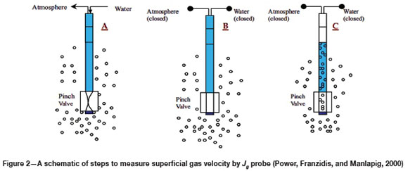
Superficial gas velocity, Jg, is a measure of aeration ability (Gorain, Franzidis, and Manlapig, 1997). In order to measure Jg, a probe similar to those used by Gorain, Franzidis, and Manlapig (1996) and Power, Franzidis, and Manlapig (2000) was used. It consisted of a transparent tube with a pneumatic pinch valve at the bottom, and the other end was closed. The probe was completely filled with water, and placed in a proper position in the cell. The pinch valve was then opened to allow the air bubbles to move up the probe and displace the water. By measuring the water discharge time, Td, between two points at distance L, the superficial gas velocity was calculated as:
Figure 2 shows the steps to measure superficial gas velocity by Jg probe.
The bubble size was measured using a bubble size analyser based on the design of Gomez and Finch (2007). Figure 3 shows a schematic of the bubble size analyser.
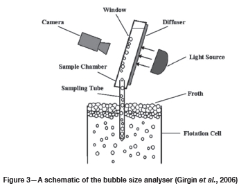
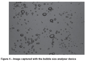
The device included a sampling tube connected to a sloped viewing chamber with rear illumination. The sloped view helps provide an approximately single plane of bubbles. The images of the bubble population were taken by a digital camera and analysed using ImageJ software version 1.50. A typical image of bubbles is shown in Figure 4. Each measurement was conducted at least twice and on average over 5000 bubbles were sized on each run.
The mean bubble diameter adopted was the Sauter mean bubble diameter, d32. The d32represents the size of a bubble with the same ratio of volume to surface as the total distribution, and is calculated as follows (Gorain, Franzidis, and Manlapig, 1997):
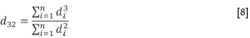
where d is diameter of the bubble and n is total number of bubbles.
Similarly to the work of Gomez and Finch (2007) and Vinnett, Yianatos, and Alvarez (2014), the gas dispersion parameters were measured at the same position for all the tests, halfway between the cell wall and the froth crowder and just below the pulp-froth interface. In order to generate reliable measurements of Jgand d32, multiple readings were averaged. The froth retention time and the bubble surface area flux were then calculated according to Equations [3] and [5], respectively.
Sampling for metallurgical evaluation
All experiments were carried out in two consecutive working shifts to limit the feed grade variations, while the feed rate, solid content, and chemical reagent dosages were kept constant. The enrichment ratio (Equation [9]) and the concentrate mass recovery (Equation [10], were used as the metallurgical parameters. This was similar to the work of Yianatos et al. (2001), who used these parameters for industrial rougher cell characterizations.
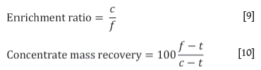
where t, c, and f are the grades of the tails, concentrate, and feed, respectively.
Samples of feed, concentrate, and tailings were taken at each operating condition and subjected to chemical analysis for sulphur content.
Results and discussion
Effect of froth depth and impeller speed on gas dispersion properties
Superficial gas velocity
Figure 5 shows that the superficial gas velocity, J, increased with increasing froth depth and impeller speed. The mechanism of impeller speed is simple, as it can be shown that the air suction increases with increasing impeller speed, and according to Equation [4], as a result the superficial gas velocity is also increased.
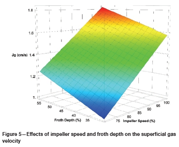
The flotation cell was provided with a froth crowder, with the shape of an inverted cone, to accelerate the froth discharge to the concentrate overflow. It had about 45 degrees of slope and it made the cell cross-sectional area at the pulp-froth interface level change by varying the froth depth. Therefore, it was impossible to predict the change in Jgwith the froth depth variations, due to the simultaneous changes in gas rate and cross-sectional area at the pulp-froth interface level. The results show that the superficial gas velocity increases with increasing froth depth (Figure 5), indicating a dominant effect of the gas rate on Jg.
It can also be seen from Figure 5 that there is a dominant effect of impeller speed on J . It is clear that manipulating the froth depth is not a feasible option to improve J, because increasing the froth depth increases the cross-sectional area at the pulp-froth interface level, which then affects the Jg, inversely.
Bubble size
The Sauter mean bubble diameter, d32, increases with increasing impeller speed and froth depth (Figure 6) due to the direct relationship between the superficial gas velocity and the Sauter mean bubble diameter (Gorain, Franzidis, and Manlapig, 1995a, 1995b; Nesset et al., 2006; Grau, Nousiainen, and Yanez, 2014; Vinnett, Yianatos, and Alvarez, 2014).
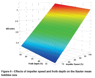
Note that the effect of impeller speed on the bubble size might appear contradictory. In forced-air flotation machine, increasing the impeller speed decreases d32, due to the increased shear force (Gorain, Franzidis, and Manlapig, 1995a, 1995b; Grau and Heiskanen, 2005; Grau, Nousiainen, and Yanez, 2014). However, Nesset, Zhang, and Finch (2012) found that the impeller speed did not significantly impact the bubble size over a wide operating range of impeller speeds. On the other hand, in a self-aerated flotation machine, as Girgin et al. (2006) stated, increasing the impeller speed improves the bubble size, due to the increased gas rate. Their study was conducted in a laboratory-scale machine and in a two-phase system. The results obtained were confirmed in an industrial-scale flotation machine where three phases were present. It seems that in a self-aerated flotation machine, gas rate is more pronounced than the added shear, which results in a larger
The measured bubble sizes, as shown in Figure 6, are slightly larger than the common range in industrial flotation cells. The main reason is that the frother concentration was low in the operating cell.
Bubble surface area flux
As can be seen from Figure 7, the maximum bubble surface area flux, Sb, is obtained at the deepest froth depth and the highest impeller speed. As shown earlier, the impeller speed had a predominant effect on Jgand d32, while Figure 6 shows that froth depth has a predominant effect on Sb. This means that the same Sbvalues can be obtained from different combinations of Jgand d32, as was observed by Vinnett, Yianatos, and Alvarez (2014).
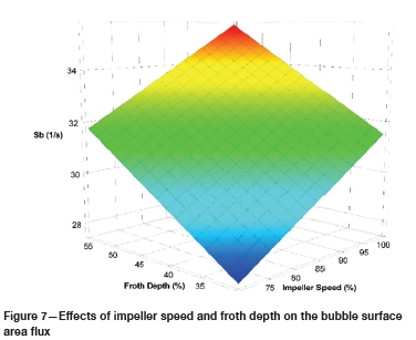
Furthermore, as shown in Figures 5, 6, and 7, increasing the impeller speed or froth depth increased Jg, d32 and Sb simultaneously. This means that there is a dominant effect of Jg on Sb. This finding implies that increasing the impeller speed and the froth depth could increase the overall flotation rate constant, due to the increased Sb(see Equation [6]). This is investigated in the next sections.
Effects of froth depth and impeller speed on the froth retention time
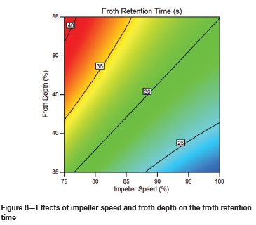
In each experiment, based on adjusted froth depth and measured Jg, the froth retention time, tf, was calculated. The effect of impeller speed on the froth retention time is shown on Figure 8. The froth retention time decreased with increasing impeller speed, due to the increased gas rate. On the other hand, despite the increased gas rate with increasing froth depth, the froth retention time increased, which indicated a major effect of froth depth in determining tf(see Equation [3]). This means that the superficial gas velocity variations, as a result of froth depth changing, have a less significant effect on the froth retention time.
Metallurgical performance evaluation
The metallurgical performance of the flotation cell was evaluated under various predetermined conditions of froth depth and impeller speed by using the enrichment ratio and the concentrate mass recovery, which indicate the flotation selectivity and flotation rate, respectively. The results show that the enrichment ratio is decreased with increasing impeller speed or decreasing froth depth, as can be seen from Figure 9, whereas the concentrate mass recovery is increased.
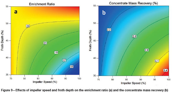
As can be seen from Figures 7, 8, and 9, the impeller speed and the froth depth affect the metallurgical performance by varying the froth retention time and the bubble surface area flux. This is discussed in detail below.
Effect of froth retention time
As can be seen from Figures 8 and 9a, the enrichment ratio increases with increasing froth depth and froth retention time. Deeper froths are generally associated with higher concentrate grades, since deeper froths allow longer froth retention times, resulting in more time for coalescence of bubbles and drainage of unattached material, including entrained gangue or low-grade particles (Hadler et al., 2012).
Bubble coalescence is one of the important froth phenomena that cause particle detachment in the froth zone (Ata, 2012), and drainage is also helpful to increase the quality of the final concentrate by rejecting the entrained hydrophilic fine particles to the pulp phase (Ata, Ahmed, and Jameson, 2004; Zheng, Franzidis, and Johnson, 2006). On the other hand, if the rate of coalescence is reduced, as a result of decreased froth retention time, the number of particles being lost from the froth and returning to the pulp zone will also be reduced (Rahman, Ata, and Jamson, 2015a).
The froth retention time affects the overall flotation recovery, mainly via changes in the froth phase recovery (Mathe et al., 1998). Thus, the recovery in the froth zone could be improved as a result of the minimization of bubble coalescence in this zone with decreasing froth depth or increasing impeller speed.
Effect of bubble surface area flux
The bubble surface area flux, Sb, has a strong correlation with flotation rate constant (Gorain, Franzidis, and Manlapig, 1997; Hernandez, Gomez, and Finch, 2003), while on the other hand it has an inverse relationship with concentrate grade (Nesset et al., 2006). This is because the greater the surface area of bubbles, the greater the probabilities of bubble-particle collision and attachment (Gorain, Franzidis, and Manlapig, 1999; Rahman, Ata, and Jameson, 2015a; Tabosa et al., 2016). This increases the flotation rate of particles with weak hydrophobicity (Rahman, Ata, and Jameson, 2015a), and as a result the concentrate mass recovery increases.
As previously shown in Figure 7, increasing both the impeller speed and froth depth improved bubble surface area flux, and according to Equation [6] it is expected that the overall flotation rate constant would increase with increasing impeller speed and froth depth.
As can be seen from Figure 9b, increasing impeller speed improves concentrate mass recovery, due to increased Sband decreased tf. Although increasing the froth depth increases Sb, the concentrate mass recovery is decreased, due to the increased tf(see Figures 7 and 8). Therefore, it can be concluded that in self-aerated flotation machines, the froth depth affects the overall flotation recovery mostly via the froth retention time. In other words, the froth depth has an insignificant effect on the overall flotation recovery by improving the bubble surface area flux. Thus, it is suggested that the froth depth should never be used to improve gas dispersion properties, whereas the impeller speed had two important impacts on the metallurgical performance by influencing both froth retention time and bubble surface area flux in the froth and pulp zones, respectively.
It should be noted that the impeller speed also affects the metallurgical performance through other mechanisms. For example, increasing the impeller speed improves solid suspension and bubble-particle collision efficiency in the pulp zone, resulting in an increase in the overall flotation recovery. However, in this study just the gas dispersion properties and the froth retention time were investigated.
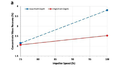
Interaction effects of operational variables
The interaction effects of froth depth and impeller speed are more important than their individual effects. For example, at a high froth depth, the impeller speed has no effect on the enrichment ratio and increases the concentrate mass recovery only slightly, as seen in Figure 10. At a low froth depth, increasing the impeller speed improves the concentrate mass recovery. This suggests that deeper froths, due to the increased froth retention time, have a great effect on metallurgical performance, while the impeller speed has only a small effect on the overall recovery.

At low froth depth (low froth retention time) the metallurgical efficiency is influenced by the cell hydrodynamic conditions, especially gas dispersion properties. In this case, the froth recovery is almost 100%, due to low froth retention time, and the pulp recovery plays a major role in determining the flotation performance. It is obvious that increasing the impeller speed improves the gas dispersion and solid suspension efficiencies, resulting in an increase in the transfer of valuable and middling particles and some fine gangue particles to the froth phase and, as a result, the overall flotation recovery increases.
On the other hand, at high froth depth (high froth retention time) the froth recovery plays a major role in determining the flotation performance. However, this does not mean that the metallurgical performance is not influenced by the impeller speed. As Figure 10a shows, at high froth depth the concentrate mass recovery improves with increasing impeller speed. The main reason is that increasing the impeller speed increases the transfer of valuable and middling particles to the froth phase. Despite upgrading in the deep froth zone, the recovery of valuable particles increases, resulting in an improved concentrate mass recovery with no negative effect on enrichment ratio. Therefore, based on the results in Figure 10, it is suggested that with deeper froths, the impeller speed should be kept high to improve hydrodynamic conditions and, consequently, to maximize flotation performance.
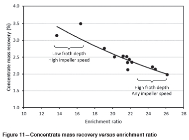
Figure 11 shows the concentrate mass recovery against the enrichment ratio as a single curve. The overall trend is a decrease in enrichment ratio with increasing concentrate mass recovery. There are two areas of operating conditions. The upper part of the curve corresponds to a high impeller speed and a low froth depth, increasing the concentrate mass recovery. The lower part corresponds to deeper froths with a wide range of impeller speeds. This graph shows that by adjusting the operational variables alone, the metallurgical target can be achieved.
Operating strategies for self-aerated flotation machines
In this section a strategy for operating self-aerated flotation cell based on varying froth depth and impeller speed with regard to the cell duty, e.g. rougher, scavenger, or cleaner, is proposed. Depending on the type of ore being processed and the flotation duties, achieving a desirable recovery or high concentrate grade will be the main metallurgical target (Power, Franzidis, and Manlapig, 2000).
Rougher or scavenger duties
The main objective of rougher or scavenger flotation banks is to achieve maximum recovery at minimum acceptable concentrate grade (Yianatos, Henriquez, and Oroz, 2006). Thus, it is suggested that the flotation cell operates at low froth depth and high gas rate (Schwarz and Alexander, 2006; Hadler et al., 2012; Rahman, Ata, and Jameson, 2015a). As previously mentioned, the low froth depth and the high gas rate decrease the froth retention time and improve the gas dispersion properties, which provides a maximum mass pull and high flotation recovery.
In a self-aerated flotation cell, it is impossible to achieve a low froth depth and high gas rate simultaneously by adjusting the froth depth alone, because decreasing the froth depth decreases the gas rate. Thus, it is necessary that the gas rate increases with increasing impeller speed. It is suggested that in rougher or scavenger duties, the impeller speed be increased to provide a high gas rate, then the froth depth decreases to provide the maximum recovery as the metallurgical target.
It should be noted that the impeller speed can be increased to a maximum allowable that prevents flooding conditions. Flooding conditions occurs at very high gas rates when the impeller is unable to disperse air properly, resulting in huge slugs of bubbles moving up near the shaft and giving a boiling appearance on the surface (Gorain, Franzidis, and Manlapig, 1999). This is undesirable as the flotation performance rapidly decreases. It has been found that coarser and denser particles need more turbulence to improve the collision rate and solid suspension efficiency (Rodrigues, Leal Filho, and Masini, 2001). Therefore, depending on the nature of flotation feed, including particle size and density, an optimum impeller speed and turbulence are required (Deglon, 2005).
Cleaner duty
Self-aerated flotation machines are commonly employed for rougher or scavenger duties (Shean and Cilliers, 2011). It is necessary to use a different operating strategy if they operate as cleaners in flotation banks.
The main objective of cleaner flotation banks is to achieve maximum concentrate grade at an acceptable recovery. Thus, it is suggested that the cleaner flotation cell operates at high froth depth and low gas rate to improve the froth retention time and upgrading in the froth zone (Cooper et al., 2004; Schwarz and Alexander, 2006; Shean and Cilliers, 2011; Hadler et al., 2012).
From a practical point of view, it is impossible to achieve a high froth depth and low gas rate simultaneously by adjusting the froth depth alone. Thus, it is necessary that the gas rate decreases with decreasing impeller speed. However, the impeller has some limitations related to minimum speed. The impeller is responsible for the gas dispersion, solid suspension, and bubble-particle collisions (Power, Franzidis, and Manlapig, 2000; Rodrigues, Leal Filho, and Masini, 2001; Deglon, 2005) and also, as mentioned earlier, flotation requires a certain degree of turbulence depending on the size and density of particles. Hence, an excessively reduced impeller speed causes a rapid decrease in metallurgical performance. It seems that in cleaner duty, decreasing the gas rate by changing the froth depth or impeller speed is a major issue.
With respect to the interaction effects between impeller speed and froth depth, in deeper froths, with increasing impeller speed, despite increasing the gas rate, there is no negative effect on enrichment ratio (see Figure 10b). Thus it is suggested that in cleaner flotation banks the cell be operated at high froth depth and high impeller speed. Although the high impeller speed provides a high gas rate and as a result increases the entrainment and the recovery of less hydrophobic particles to the froth phase, the high froth depth provides upgrading in the froth zone.
To achieve this, it is necessary to increase the impeller speed to a point where flooding conditions are prevented, then the froth depth should be increased to a point such that the amount of froth overflow product is acceptable and the target concentrate grade is achieved.
It seems that the strategy of decreasing the gas rate for cleaner duty is applicable only to forced-air flotation machines, because the gas rate is an independent variable and can be decreased without decreasing the impeller speed. In self-aerated flotation machines, it is impossible to decrease the gas rate by varying the impeller speed with no negative effect on the efficiencies of solid suspension and gas dispersion.
Conclusions
The effects of froth depth and impeller speed on gas dispersion parameters, froth retention time, and metallurgical performance were investigated in an industrial self-aerated flotation machine. The following conclusions can be drawn from the results presented in this paper.
> There was a positive relationship between the operational variables (froth depth and impeller speed) and the gas dispersion parameters (superficial gas velocity, bubble size, and bubble surface area flux).
> Froth depth had a small effect on the superficial gas velocity, due to the simultaneous changes in the gas rate and cross-sectional area at the pulp-froth interface level. Therefore it is suggested that varying the froth depth is not a feasible option to improve superficial gas velocity.
> With increasing impeller speed and froth depth, despite an increase in the superficial gas velocity, Jg, and the Sauter bubble mean diameter, d32, the bubble surface area flux, Sb, increased. This means that there was a dominant effect of Jg onSb.
> Despite the increased gas rate with froth depth, the froth retention time, tf, was increased, which indicated a major effect of froth depth on tf. In other words, increased superficial gas velocity with froth depth had a less significant effect on the froth retention time.
> The froth depth affected the metallurgical performance mostly via changing the froth retention time. In that, the froth depth had an insignificant effect on the flotation performance by improving the bubble surface area flux. The impeller speed had two important effects on the metallurgical performance via varying both froth retention time and bubble surface area flux in the froth and pulp zones, respectively.
> There was an interaction effect between impeller speed and froth depth. It was found that at a low froth depth the impeller speed plays a major role in determining the flotation efficiency, due to increased gas dispersion efficiency, while at a high froth depth the metallurgical performance was influenced mainly by increased froth retention time.
> A strategy for operating self-aerated flotation machines based on varying froth depth and impeller speed with regard to the cell duty, e.g. rougher, scavenging, or cleaner, is as proposed. It is suggested that operating under high gas rate, by increasing impeller speed alone, is the best strategy for obtaining high metallurgical performance, because it prevents the reduction of solid suspension and gas dispersion efficiencies. Then, depending on the cell duty, the froth depth should be manipulated to achieve the metallurgical target.
Acknowledgements
The authors thank Gol Gohar Iron Mining Complex for their support and collaboration throughout the course of this research.
References
Ata, S. 2012. Phenomena in the froth phase of flotation - A review. International Journal of Mineral Processing, vol. 102-103. pp. 1-12. [ Links ]
Ata, S., Ahmed, Ν., and Jameson, G.J. 2004. The effect of hydrophobicity on the drainage of gangue minerals in flotation froths. Minerals Engineering, vol. 17, no. 7-8. pp. 897-901. [ Links ]
Ata, S. and Jameson, G.J. 2013. Recovery of coarse particles in the froth phase - A case study. Minerals Engineering, vol. 45. pp. 121-127. [ Links ]
Cooper, M., Scott, D., Dahlke, R., Finch, J.A., and Gomez, CO. 2004. Impact of air distribution profile on banks in a Zn cleaning circuit. Proceedings of the 36th Annual Meeting of the Canadian Mineral Processors of CIM, Ottawa, Ontario, Canada, October. CIM, Montreal. pp. 525-540. [ Links ]
Deglon, D.A. 2005. The effect of agitation on the flotation of platinum ores. Minerals Engineering, vol. 18, no. 8. pp. 839-844. [ Links ]
Dobby, G.S. 1984. A fundamental flotation model and flotation column scale-up. PhD thesis, Department of Mining and Metallurgical Engineering, McGill University, Montreal, Canada. [ Links ]
Finch, J.A., xiao, J., Hardie, C., and Gomez, CO. 2000. Gas dispersion properties: bubble surface area flux and gas holdup. Minerals Engineering, vol. 13, no. 4. pp. 365-372. [ Links ]
Fournier, J., Hardie, C., Torrealba, J., and Nesset, J.E. 2015. A review of gas dispersion studies in flotation plants. Proceedings of the 47th Annual Canadian Mineral Processors Operators Conference, Ottawa, Ontario, January. CIM, Montreal. pp. 207-233. [ Links ]
Girgin, E.H., Do, S., Gomez, CO., and Finch, J.A. 2006. Bubble size as a function of impeller speed in a self-aeration laboratory flotation cell. Minerals Engineering, vol. 19, no. 2. pp. 201-203. [ Links ]
GooDALL, C.M. and O'Connor, C.T. 1989. Residence time distribution studies of the solid and liquid phases in a laboratory column flotation cell. Proceedings of the International Colloquium: Developments in Froth Flotation, Cape Town, South Africa, 3-4 August 1989. Volume 2. Southern African Institute of Mining and Metallurgy, Johanneburg. http://www.saimm.co.za/Conferences/FrothFlotation/004-Goodall.pdf [ Links ]
Gomez, C.O. and Finch, J.A. 2007. Gas dispersion measurements in flotation cells. International Journal of Mineral Processing, vol. 84, no. 1-4. pp. 51-58. [ Links ]
Gorain, B.K., Franzidis, J.-P., and Manlapig, E.V. 1995a. Studies on impeller type, impeller speed and air flow rate in an industrial scale flotation cell. Part 1: Effect on bubble size distribution. Minerals Engineering, vol. 8, no. 6. pp. 615-635. [ Links ]
Gorain, B.K., Franzidis, J.P., and Manlapig, E.v. 1995b. Studies on impeller type, impeller speed and air flow rate in an industrial flotation cell. Part 2: Effect on gas hold-up. Minerals Engineering, vol. 8, no. 12. pp. 1557-1570. [ Links ]
Gorain, B.K., Franzidis, J.-P., and Manlapig, E.v. 1996. Studies on impeller type, impeller speed and air flow rate in an industrial scale flotation cell. Part 3: Effect on superficial gas velocity. Minerals Engineering, vol. 9, no. 6. pp. 639-654. [ Links ]
Gorain, B.K., Franzidis, J.-P., and Manlapig, E.v. 1997. Studies on impeller type, impeller speed and air flow rate in an industrial scale flotation cell. Part 4: Effect of bubble surface area flux on flotation performance. Minerals Engineering, vol. 10, no. 4. pp. 367-379. [ Links ]
Gorain, B.K., Franzidis, J.-P., and Manlapig, E.v. 1999. The empirical prediction of bubble surface area flux in mechanical flotation cells from cell design and operating data. Minerals Engineering, vol. 12, no. 3. pp. 309-322. [ Links ]
Grau, R. and Heiskanen, H. 2005. Bubble size distribution in laboratory scale flotation cells. Minerals Engineering, vol. 18, no. 12. pp. 1164-1172. [ Links ]
Grau, R., Nousiainen, M., and YaNez, A. 2014. Gas dispersion measurements in three Outotec flotation cells: TankCell 1, e300 and e500. Proceedings of the 27th International Mineral Processing Congress, Santiago, Chile, 20-24 October. Gecamin Ltda. [ Links ]
Hadler, K. and Cilliers, J.J. 2009. The relationship between the peak in air recovery and flotation bank performance. Minerals Engineering, vol. 22, no. 5. pp. 451-455. [ Links ]
Hadler, K., Greyling, M., Plint, N., and Cilliers, J.J. 2012. The effect of froth depth on air recovery and flotation performance. Minerals Engineering, vol. 36-38. pp. 248-253. [ Links ]
Hernandez, H., Gomez, C.O., and Finch, J.A. 2003. Gas dispersion and de-inking in a flotation column. Minerals Engineering, vol. 16, no. 8. pp. 739-744. [ Links ]
Hernandez-Aguilar, J.R. and Reddick, S. 2007. Gas dispersion management in a copper/molybdenum separation circuit. Proceedings of the Sixth International Copper-Cobre Conference, Toronto, Canada, 25-30 August 2007 Vol. 2. Del Villar, R., Nesset, J.E., Gomez , C.O., and Stradling, A.W. (eds.). CIM, Montreal. pp 173-184. [ Links ]
Mathe, Z.T., Harris, M.C., O'Connor, C.T., and Franzidis, J.-P. 1998. Review of froth modelling in steady state flotation systems. Minerals Engineering, vol.11, no. 5. pp. 397-421. [ Links ]
Nesset, J.E., Hernandez-Aguilar, J.R., Acuna, C., Gomez, C.O., and Finch, J.A. 2006. Some gas dispersion characteristics of mechanical flotation machines. Minerals Engineering, vol. 19, no. 6-8. pp. 807-815. [ Links ]
Nesset, J.E., Zhang, W., and Finch, J.A. 2012. A benchmarking tool for assessing flotation cell performance. Proceedings of the 44th Annual Canadian Mineral Processors Operators Conference, Ottawa, Ontario, Canada, 17-19 January. CIM, Montreal. pp. 183-209. [ Links ]
Power, A., Franzidis, J.-P., and Manlapig, E.V. 2000. The characterization of hydrodynamic conditions in industrial flotation cells. Proceedings of the 7th Mill Operators' Conference, Kalgoorlie, Western Australia, 12-14 October, Australasian Institute of Mining and Metallurgy, Melbourne. pp. 243-256. [ Links ]
Rahman, R.M., Ata, S., and Jameson, G.J. 2015a. Study of froth behavior in controlled plant environment - Part 1: Effect of air flow rate and froth depth. Minerals Engineering, vol. 81. pp. 152-160. [ Links ]
Rahman, R.M., Ata, S., and Jameson, G.J. 2015b. Study of froth behavior in controlled plant environment - Part 2: Effect of collector and frother concentration. Minerals Engineering, vol. 81. pp. 161-166. [ Links ]
Rodrigues, W.J., Leal Filho, L.S., and Masini, E.A. 2001. Hydrodynamic dimensionless parameters and their influence on flotation performance of coarse particles. Minerals Engineering, vol. 14, no. 9. pp. 1047-1054. [ Links ]
Schubert, H. and Bischofberger, C. 1978. On the hydrodynamics of flotation machines. International Journal of Mineral Processing, vol. 5, no. 2. pp. 131-142. [ Links ]
Schwarz, S. and Alexander, S. 2006. Gas dispersion measurements in industrial flotation cells. Minerals Engineering, vol. 19, no. 6-8. pp. 554-560. [ Links ]
Seguel, F., Soto, 1., Krommenacker, N., Maldonado, M., and Becerra Yoma, N. 2015. Optimizing flotation bank performance through froth depth profiling: Revisited. Minerals Engineering, vol. 77. pp. 179-184. [ Links ]
Shean, B.J. and Cilliers, J.J. 2011. A review of froth flotation control. International Journal of Mineral Processing, vol. 100, no. 3-4. pp. 57-71. [ Links ]
Smith, C., Neethling, S.J., and Cilliers, J.J. 2008. Air-rate profile optimisation: From simulation to bank improvement. Minerals Engineering, vol. 21, no. 12-14. pp. 973-981. [ Links ]
Tabosa, E., Runge, K., Holtham, P., and Duffy, K. 2016. Improving flotation energy efficiency by optimizing cell hydrodynamics. Minerals Engineering, vol. 96-97. pp. 194-202. [ Links ]
Venkatesan, L., Harris, A., and Greyling, M. 2014. Optimization of air rate and froth depth in flotation using a CCRD factorial design - PGM case study. Minerals Engineering, vol. 66-68. pp. 221-229. [ Links ]
Vera, M.A., Franzidis, J.-P., and Manlapig, E.V. 1999. Simultaneous determination of collection zone rate constant and froth zone recovery in a mechanical flotation environment. Minerals Engineering, vol.12, no. 10. pp. 1163-1176. [ Links ]
Vinnett, L., Yianatos, J., and Alvarez, M. 2014. Gas dispersion measurements in mechanical flotation cells: Industrial experience in Chilean concentrators. Minerals Engineering, vol. 57. pp. 12-15. [ Links ]
Yianatos, J., Bergh, L., and Cortes, G. 1998. Froth zone modelling of an industrial flotation column. Minerals Engineering, vol. 11, no. 5. pp. 423-435. [ Links ]
Yianatos, J., Bergh, L., Condori, P., and Aguilera, J. 2001. Hydrodynamic and metallurgical characterization of industrial flotation banks for control purposes. Minerals Engineering, vol. 14, no. 9. pp. 1033-1046. [ Links ]
Yianatos, J., Henriquez, F.H., and Oroz, A.G. 2006. Characterization of large size flotation cells. Minerals Engineering, vol. 19, no. 6-8. pp. 531-538. [ Links ]
Yianatos, J., Contreras, F., and DIaz, F. 2010. Gas holdup and RTD measurement in an industrial flotation cell. Minerals Engineering, vol. 23, no. 2. pp. 125-130. [ Links ]
Zheng, X., Franzidis, J.-P., and Manlapig, E. 2004. Modelling of froth transportation in industrial flotation cells: Part I. Development of froth transportation models for attached particles. Minerals Engineering, vol. 17, no. 9-10. pp. 981-988. [ Links ]
Zheng, X., Franzidis, J.-P., and Johnson, N.W. 2006. An evaluation of different models of water recovery in flotation. Minerals Engineering, vol. 19, no. 9. pp. 871-882. [ Links ]
Zheng, X., Johnson, N.W., and Franzidis, J.-P. 2006. Modelling of entrainment in industrial flotation cells: water recovery and degree of entrainment. Minerals Engineering, vol. 19, no.11. pp. 1191-1203. [ Links ]
 Correspondence:
H. Naghavi
h.naghavi@stu.yazd.ac.ir
Received: 28 Jul. 2018
Revised: 19 Dec. 2018
Accepted: 15 Feb. 2019
Published: July 2019

