


Services on Demand
Article
 English (pdf)
 Article in xml format
 Article references
Indicators

Related links
-
 Cited by Google
 -
 Similars in Google
Share

 Permalink
Journal of the Southern African Institute of Mining and Metallurgy
On-line version ISSN 2411-9717
Print version ISSN 2225-6253
J. S. Afr. Inst. Min. Metall. vol.119 n.7 Johannesburg Jul. 2019
http://dx.doi.org/10.17159/2411-9717/536/2019
STUDENT PAPERS
Developing a mining plan for restarting the operation at Uis mine
J.H. Maritz*; S. Uludag
University of Pretoria, South Africa
SYNOPSIS
AfriTin Mining Limited plans to reopen the Uis tin mine in Namibia and establish a pilot processing plant for phase 1 of the Uis tin project, which is scheduled to commence in the last quarter of 2018 . A mining plan is required for phase 1 to supply the new pilot processing plant with 500 kt of run-of-mine ore per annum, for a period of 5 years. New geological mapping and three-dimensional modelling of the mining area were utilized to identify the most optimal mining locations that require low initial waste stripping. An open-pit mining method was selected to target the surface outcrops of the pegmatite orebodies. The mine design criteria were determined and used as input to generate the mine design by utilizing professional engineering software. The mine design was optimized and an overall stripping ratio of 0.81 was achieved. A 5-year production schedule was developed for the mine design according to quarterly periods of three months. A fixed production target of 125 kt of ore was assigned to the quarterly periods, and a ramp-up production target of 65 kt of ore was assigned for the first period. The mobile mining equipment requirements were calculated, and recommendations were made for implementing the 5-year mining plan.
Keywords: mining plan, mine design criteria, production schedule, optimal, stripping ratio.
Introduction
AfriTin Mining Limited is the owner of the Uis tin project in Namibia and plans to reopen the Uis tin mine, which is located near the town of Uis, approximately 164 km north of Swakopmund. The Uis tin mine was owned and operated by Imkor Tin, a subsidiary of Iscor South Africa. Mining commenced in 1958, and the operation was closed in 1991. Steffen Robertson & Kirsten (SRK) defined the life of mine (LOM) plan for the historical Uis mine in 1989. The SRK report estimated the historical resources and reserves, which consisted of sixteen cassiterite-bearing pegmatite orebodies. SRK developed the most economical pit designs to provide the highest average tin grade at the lowest practical waste stripping ratio. Exploration data from the SRK report of 1989 was used extensively throughout this study, since no new exploration drilling has been conducted. The pegmatites are present as large, subvertical and outcropping veins up to 100 m in thickness. Once phase 1 is operational, mining will be conducted using conventional open pit mining methods. Initial production will be from exposed pegmatite veins in the old mine workings. AfriTin plans to establish a pilot processing plant by the end of 2018 to beneficiate run-of-mine ore at a rate of 500 kt per annum.
Project background
Phase 1 of the project required a mining plan for the reopening of the mine. This study focused on developing the phase 1 mining plan to supply the pilot processing plant with run-of-mine ore at a rate of 500 kt/a for a period of five years. The mining plan included a detailed mine design and production schedule for the phase 1 operation. The mining locations with the lowest stripping ratios were identified, and the opportunities and constraints of the historical pit excavations were considered in the mine design.
A detailed production schedule was developed for the optimal pit designs. The production schedule precisely identifies when and where mining must take place within the mine design to meet the required tonnages. The mining plan also provides recommendations for the required mobile mining equipment based on the production schedule.
Objectives and methodology
The following objectives were formulated.
> Develop the mine design criteria by utilizing historical information and a research-based approach
> Analyse the topographical surface and the geological block model of the mining area to identify alternative mining locations that will yield maximum grade
> Generate optimal pit designs for the V1 and V2 pegmatite orebodies with the lowest practical waste stripping ratio by utilizing professional mine design software
> Develop an optimal mining sequence that minimizes waste stripping by extracting the outcropping veins first, and strategically mining at locations that yield easy ore extraction
> Develop the waste and ore hauling routes using professional mine design software and satellite images
> Establish the most suitable mobile mining equipment fleet that minimizes hauling distances by utilizing first-principle calculations.
The research for this study was conducted on each of the mine design criteria. Furthermore, reports and articles related to the historical mining and processing operation were studied and the mine was visited to investigate the historical pits. Suitable mining methods for the operation were considered and compared. The ore definition and modifying factors associated with the mineable resource were determined. The company provided a three-dimensional geological model as input to the mining plan. The mining layout, mining limits, and pit design were developed using professional mine design software in cooperation with the mining engineer of AfriTin. The locations for the overburden dumps were determined and the hauling routes were designed. Subsequently, a mine production schedule was generated, again using proprietary scheduling software. The mobile mining equipment requirements were modelled based on the results of the mine production schedule. Finally, directives related to the management of the mining operation were established.
Scope of study
The mining plan is limited to the V1 and V2 pegmatite orebodies, which have been determined as the target for phase 1. This study focuses only on the primary mineral, cassiterite, and does not include any recommendations for secondary minerals contained in the V1 and V2 pegmatites. The methodology for developing the mining plan is applicable only to similar open-pit mining operations. The mining plan includes a mine design, production schedule, and recommendations for mobile mining equipment. A financial analysis is not included in this study.
Literature review
Geology and mineralization
The SRK (1989) historical estimates determined that the V1 and V2 pegmatite orebodies comprised approximately 50% of the total mineable reserves. The V1 and V2 pegmatites were reported with a tin grade of approximately 0.139%, which is higher than the overall reserve grade. The stripping ratios for the V1 and V2 pegmatites are economically favourable compared with the other pegmatites (Steffen Robertson & Kirsten, 1989).
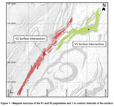
The lack of digital information regarding the V1 and V2 pegmatites gave rise to a new mapping of both orebodies, conducted by AfriTin. High-resolution geological mapping and three-dimensional modelling of the V1 and V2 orebodies were completed at the beginning of 2018. The mapping exercise gave more confidence in the data that was used in the mine plan. One of the more important outcomes of the mapping was the extension of the V2 pegmatite to the southwest of the pit, enabling the extent of the V1 and V2 pegmatites orebodies to be accurately identified for planning purposes. The map of the V1 and V2 pegmatites is shown in Figure 1.
Geotechnical considerations
The SRK report of 1989 provided the historical pit parameters and stated that the ground conditions at the Uis tin mine are stable under these parameters. The following is a list of the historical pit parameters (Steffen Robertson & Kirsten, 1989):
> Mining bench heights for V1/V2 pit are 15 m
> Road and ramp widths are 20 m
> Maximum road gradient is 10%
> Minimum working width at pit floor is 20 m
> Minimum cutback working width from toe to crest is 40 m.
The old V1/V2 pit design done by SRK in 1989 used slope angles of 60° for pegmatite and between 44° and 53.5° for waste rock (The MSA Group, 2017). According to the SRK report of 1989, the slope stability at these angles was good and no slope failure incidents were reported.
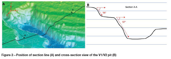
A digital terrain model (DTM) was used to inspect various historical mining locations within the V1/V2 pit. Measurements of the maximum slope angles were taken and compared to the theoretical pit parameters to prove the validity of the historical information. Figure 2 illustrates how the DTM measurements were taken. From inspection of the V1/V2 pit, it was found that most of the pit was mined at a slope angle between 55° and 60°.
Hydrogeological considerations
The area of the Uis Tin Mine has a very dry climate and the groundwater recharge is relatively low. The mining area does not receive much rain and the groundwater recharge is dependent on run-off in the Omaruru River (van Wyk, 2018). When mining for phase 1 takes place at elevations below the actual groundwater level, groundwater inflow into the pits is not considered a major risk and only limited pumping may be required due to the low groundwater recharge of the area. It is recommended that groundwater inflow should be monitored when mining for phase 1 starts, although no risk is expected.
Environmental considerations
According to the Environmental Impact Assessment study done in 2013, the Uis project can commence with the re-opening of the Uis tin mine provided that all the recommended control and mitigatory measures are in place. The following are the key findings of the EIA report (Jenneker and Williams, 2013).
> The geographical area where Uis tin mine is located is not considered a sensitive biodiverse area.
> Some negative impacts that can affect the Uis project have been identified, but these will not necessarily have any deleterious effect on the surrounding environment's biodiversity.
> The development of the Uis mine will create much-needed job opportunities, especially during the construction and operational phases. The mine will have a positive influence on the town of Uis and will contribute to the economy of Namibia.
> If the mining company maintains close interaction with the local authorities it can be expected that there will be no negative socio-economic impacts on the town of Uis.
> It is important that all the mitigating measures that were mentioned in the report are adhered to and included in a legal agreement between the relevant parties.
Economic considerations
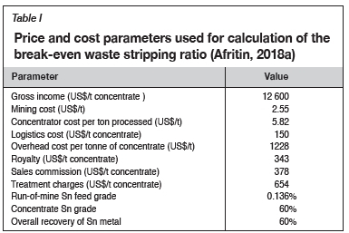
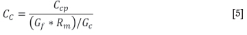
The price and cost parameters in Table I were used to determine a financial model that calculated the break-even waste stripping ratio (BESR) for phase 1. Stripping ratio is defined as the amount of waste to ore that is removed. The BESR is the stripping ratio where the cost of production equals the income from sales. Exceeding the BESR during any specific operational period will result in an operating loss.
The BESR can be calculated by equating the cost of production to the income from sales:

using the following symbols:
CM= Mining cost per ton of concentrate
CC= Concentrator cost per ton of concentrate
CL= Logistics cost per ton of concentrate
CO= Overhead costs per ton of concentrate
CY= Royalty per ton of concentrate
CS= Sales commission per ton of concentrate
CT= Treatment charges per ton of concentrate
IG= Gross income per ton of concentrate
BESR = Break-even waste stripping ratio
Cm= Mining cost per ton mined
Ccp= Concentrator cost per ton processed
Gf= Run-of-mine feed grade
Rm= Overall Sn metal recovery
Gc= Concentrate Sn grade (%)
Equation [1] can be rewritten as:

where:

The mining cost per ton of concentrate:
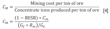
The concentrator cost per ton of concentrate:
By solving for break-even waste stripping ratio:
A BESR of 1.97 was calculated, which means that for every unit of ore mined, 1.97 times the equivalent unit of waste can be mined to break even. The BESR was used as a mine design criterion to determine the limit of the open pit mine design.
Results and discussion
Mining method
The first mining phase at Uis tin mine will implement an open pit mining method at preselected mining locations that target the V1 and V2 pegmatite surface outcrops. The V1 and V2 pegmatite orebodies will be mined by two separate open pits. The open pit mine process cycle consists of drilling and blasting to break and expose the ore, followed by loading, hauling, and dumping of the broken ore
Ore and waste determination
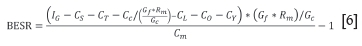
In this study 'ore' is defined as the pegmatite rock, from both the V1 and V2 pegmatite bodies, that consists of valuable mineralized material. 'Waste' is defined as the schist host rock surrounding the V1 and V2 pegmatite bodies. It should be noted that all the material outside the pegmatite bodies, within the geological model, is assumed to be waste rock. A cut-off grade method is normally used to distinguish between ore and waste material. However, due to the nature of the ore and waste rock, a simpler approach was used. The ore and waste rock have distinct colours which make them easy to identify in the pit. The visual difference between the ore and waste rock is illustrated in Figure 3.
Mine design criteria
The information gathered from the literature review was investigated to conclude the mine design criteria. The mine design criteria were used as input to the mine design for phase 1 at the Uis tin mine.
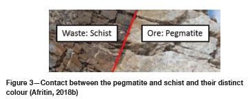
Digital terrain model (DTM)
A digital terrain model (DTM) for the Uis mining area was generated by combining a stereo pair of satellite images and 12 control points from a differential GPS survey that was conducted within the mining area. The DTM shown in Figure 4 is accurate to 1 m in the X, Y, and Z dimensions and was utilized to develop the mine design.
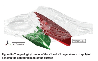
Geological model
The geological model for the V1 and V2 pegmatite bodies is shown in Figure 5. This three-dimensional geological model served as a reference point for the mine design process. The pegmatite envelopes in the geological model were used to determine the extent of the mine design. A relative density of 2.66 t/m3 was assigned to both the waste and ore material in the geological model. An average grade of 0.139% Sn was assigned to both the V1 and V2 pegmatite bodies. The geological model was used for the tonnage calculations for both waste and ore.
Geological and mining losses
The life-of-mine report by SRK (1989) assumed zero geological and mining losses, based on historical operating data and experience. For this study, it is also assumed that the geological and mining losses will be zero, as it is not expected that the nature of the ore deposit would have changed over the past three decades.
Production scheduling constraints
The production schedule was developed by assuming that the production from the different mining stages within the pit designs will proceed in a bench-by-bench fashion, starting at the top bench and moving downwards. There is a possible opportunity to split production between multiple levels within a single mining stage. However, the production schedule did not include this possibility, which resulted in a more conservative overburden stripping profile.
Pit design parameters
The historical pit parameters from the SRK report of 1989 were compared with the digital measurements of the old pit workings. It was found that the maximum slope angles were between 50° and 60°. The historical pit parameters were used together with new open-pit standards from AfriTin to determine the new pit design parameters.
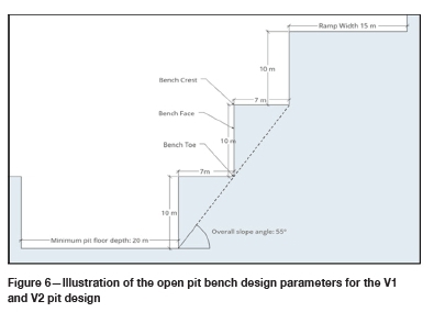
It was assumed that relatively small mining equipment, such as excavators and articulated dump trucks (ADTs), will be used for phase 1 mining. The following is a list of the new parameters used the V1 and V2 pit designs:
> Mining bench heights are 10 m
> Mining bench widths (berms) are 7 m
> The overall pit slope angle is 55° (crest-to-crest)
> Road and ramp widths are 15 m
> Maximum road gradient is 12.5%
> Minimum working width at pit floor is 20 m.
The pit parameters were modelled in a simple design and are illustrated in Figure 6 to better understand and visualize the terms.
Break-even stripping ratio
The BESR of 1.97 was calculated by utilizing the financial model. The BESR was used as a benchmark for both the mine design and the production schedule. The maximum stripping ratio of the mining sequence must not exceed the BESR.
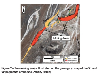
Number of mining areas
The nature of the V1 and V2 pegmatite orebodies allows for the simultaneous development of two different open pits. This decreases the production risk compared to a single pit, should an incident occur that stops mining activities within the pit, and allows for more flexible grade control. The two mining areas are illustrated in Figure 7.
Mine design
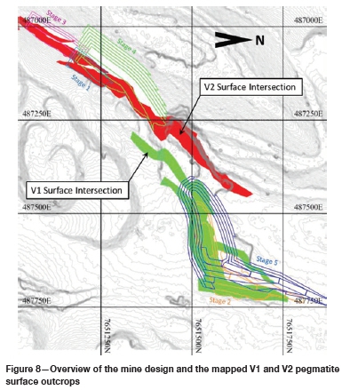
The pit designs for both the V1 and V2 pegmatite orebodies were generated with professional mine design software. The pit designs were optimized to reduce the overall stripping ratio while still adhering to the tonnage requirements of the 5-year mining plan. The pit designs were generated according to five different stages that represent the sequence for mining the two open pits.
The V1 and V2 pegmatite outcrops on the surface are illustrated in Figure 8, together with the pit designs for both the V1 and V2 pegmatite bodies.
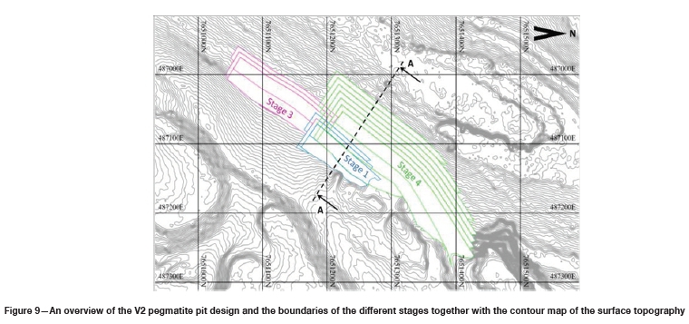
The pit design for the V2 pegmatite orebody was generated with three different stages as illustrated in Figure 9. The surface outcrops of the V2 pegmatite orebody are targeted in stage 1 and stage 3 of the pit design.
Stage 4 of the pit design will serve as a pushback with a higher incremental waste stripping ratio. The pit designs for both stage 1 and stage 3 have a total of three 10 m benches and the design for stage 4 has seven 10 m benches. Access roads for drilling machines will be developed on the hill to the northwest side of the pit.
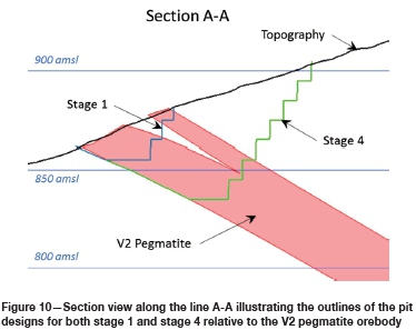
The section line A-A was generated perpendicular to the strike of the V2 pegmatite orebody. This section line was used to generate a vertical section view of the V2 pit design as illustrated in Figure 10. The pit design for stage 1 was generated mostly within the V2 pegmatite orebody, which resulted in a low waste stripping ratio. The waste stripping ratio increases during the stage 4 pushback since more waste is contained within the boundary of the pit. The southeastern boundaries of the pits were generated along the contact line between the V2 pegmatite orebody and the waste rock to reduce the waste stripping ratio.
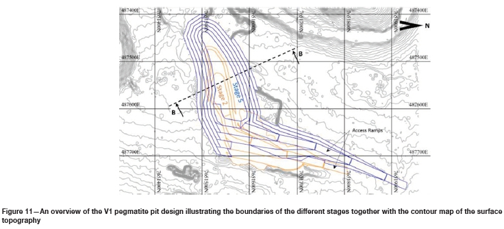
The pit design for the V1 pegmatite orebody was generated with two different stages as illustrated in Figure 11. The stage 2 design was targeted at the outlines of the historical mining excavations with the objective of deepening the historical excavations at a low waste stripping ratio. Stage 5 will serve as a pushback for stage 2 to access the ore at increasing depth. The pit design for stage 2 was generated with two 10 m benches and the design for stage 5 has a total of five 10 m benches.
The location of the access ramps was determined by utilizing the historical access ramps since the development of these access ramps will require less waste removal.
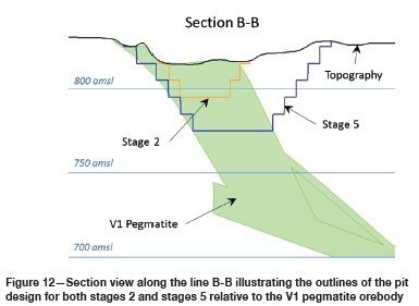
Figure 12 illustrates the stage 2 pit design generated within the boundary of the V1 pegmatite orebody to ensure a low waste tripping ratio. The stage 5 pit design was generated to access the ore at increasing depth and requires more waste removal during the pushback.
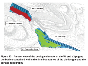
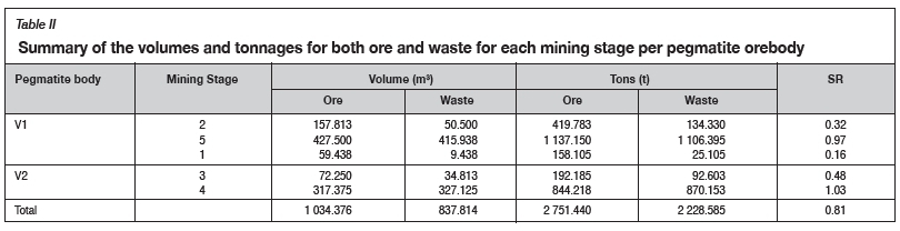
The geological block model, surface digital terrain model (DTM), and the pit designs for the different mining stages were integrated into one model as illustrated in Figure 13. This model was used to calculate the ore and waste volumes and tonnages for each mining stage. The calculated volumes and tonnages are summarized in Table II, together with the waste stripping ratio for each mining stage.
Since a low overall waste stripping ratio of 0.81 was achieved for phase 1, it has proved beneficial to implement the method of targeting the surface outcrops of the pegmatite bodies during the first stages of mining, followed by incremental pushbacks to allow access to the deepening pegmatite orebodies. The pit designs for the V1 and V2 pegmatite orebodies will give access to a total of approximately 2 751 440 t of ore throughout phase 1.
The objective of the phase 1 mining plan is to deliver ore to the pilot processing plant at a rate of 500 000 t/a for a period of five years. Therefore, phase 1 must deliver a total of 2.5 Mt of ore to the pilot processing plant. The pit designs that were generated will be sufficient for phase 1 since an excess of 251 440 t of ore can be delivered to accommodate for potential losses.
It should be noted that the information in Table II is not compliant with the SAMREC Code due to the lack of drill-hole information from the mineral exploration phase. It is possible that the in situ pegmatite bodies differ from the modelled pegmatite bodies. Therefore, the pit designs were generated to deliver excess ore tonnages to minimize the risk of the in situ orebody deviating from the modelled orebody.
Production sequence and schedule
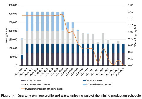
Specialist mine modelling software was used to develop a mining production schedule for the mine designs. The mine production was scheduled according to quarterly periods of three months, with mining assumed to commence on 1 October 2018. A fixed production target of 125 000 t of ore was assigned to the quarterly periods. It is assumed that the gradual ramp-up to steady state production will take approximately one period (three months). Therefore, the production target for the first period was scheduled at 62 500 t of ore to allow for the gradual ramp-up to steady-state production. The production target split is 57%/43% for the V1 and V2 pits respectively. The ratio of the split was developed based on the ore tonnages contained within each pit design shell.
The initial mining stage for both the V1 and V2 pit designs was generated to target a low waste (overburden) stripping ratio. It should be noted that the low waste stripping ratios of the initial stages do not imply that the overall waste stripping ratio for the initial periods of the production schedule will be low, since the production schedule was developed by utilizing the initial mining stages to accommodate for the simultaneous removal of the overburden of the later stages.
Stage 4 and stage 5 of the mine design have higher stripping ratios than the initial stages since more waste removal is required to access the ore at increasing depth. Therefore, the required waste removal for stages 4 and 5 will commence simultaneously with the initial mining stages. Figure 14 illustrates that the waste stripping ratio for the first nine quarters is significantly higher than the overall stripping ratio of 0.81.
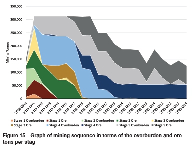
The graph in Figure 15 illustrates the mining sequence of the ore and overburden during each stage. The required overburden removal for stages 4 and 5 will commence well in advance of the planned ore mining for stages 4 and 5, as illustrated in Figure 15. Stages 1, 2, and 3 will be completely mined out within the first nine quarters, and during this period a relatively large amount of overburden from stages 4 and 5 will also be removed.
The production schedule and the mine designs were integrated into a three-dimensional scheduling model that provides yearly representations of the mining progress in terms of the face positions, as illustrated in Figure 16. The scheduling model visually represents the mining sequence and clearly identifies where mining activities will take place within the pit designs throughout phase 1. The different colours in Figure 16 represent the different mining stages and illustrate how the ore and overburden extraction will progress. The model also proved the validity of the production schedule in terms of adhering to the spatial constraints of the mine design.
Overburden and waste disposal
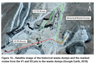
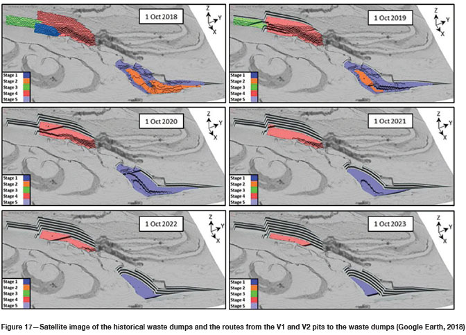
The historical waste dumps on the eastern side of the V1 and V2 pits will be used for the waste disposal during phase 1. The historical waste dumps are situated relatively close to the new pit designs for both the V1 and V2 pegmatite bodies and require little development. The routes leading from the pits to the waste dump location are shown in Figure 17.
Mobile mining equipment requirements
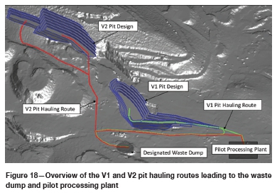
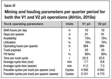
The required number of haul trucks and drill rigs was determined by first-principle calculations based on the data of the phase 1 production schedule. Hauling routes leading to the waste dump and the pilot processing plant were generated for both the V1 and V2 pit designs as shown in Figure 18. The distances and inclinations of the hauling routes were determined and used to calculate the average cycle times of a typical 25 t haul truck. The number of cycles a waste and ore truck can complete per quarter is calculated in Table III.
Typical drilling parameters for the ground conditions at the Uis tin mine are provided in Table IV.
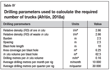
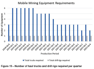
The abovementioned parameters were used to calculate the number of haul trucks and drill rigs required per quarter based on the production schedule for phase 1. Figure 19 shows the calculated equipment requirements per quarter.
Conclusions
The average stripping ratio was optimized by generating initial mining stages along the surface outcrops of the V1 and V2 pegmatite orebodies, followed by incremental pushback stages. The designs for the initial mining stages were generated with low average stripping ratios and the subsequent pushback stages were generated with higher average stripping ratios. This development strategy allows for a fast production ramp-up and limited mining infrastructure. The pre-stripping waste requirements of the pushback mining stages were significantly larger than those for the initial mining stages. The production schedule was developed by allowing the pre-stripping of the pushback stages to commence simultaneously with the initial mining stages, which resulted in the first periods of the production scheduling having a higher stripping ratio than the average stripping ratio. The mine design and production schedule were successfully optimized to ensure that the maximum stripping ratio per quarter does not exceed the break-even stripping ratio. The mobile mining equipment requirements were determined to ensure that the mining plan can be executed adequately.
The optimized mine design and production schedule presented in this study provide a recommended long-term framework for the phase 1 mining operation at the Uis tin mine. Once phase 1 is operational, the optimized 5-year mining plan will supply the pilot plant with ore at a rate of 500 000 t/a while maintaining an average waste to ore stripping ratio of less than 1.0.
Recommendations
It is recommended that the mine design and production schedule should be implemented in the phase 1 mining plan at the Uis tin mine. Exploration drilling should be conducted to improve the confidence in the geological data and the phase 1 mining plan should be revised and updated accordingly.
References
Afritin. 2018a. Afritin unit cost model v6. Illovo, South Africa. [ Links ]
Afritin. 2018b. High-resolution geological mapping and 3D modelling of the V1/V2 pegmatite, Uis Tin Mine. Illovo, South Africa. [ Links ]
Jenneker, A. and Williams, W. 2013. Environmental Impact Assessment for the re-commissioning of the Uis Tin and Tantalum Mine. EnviroSolutions, Manassas, VA. [ Links ]
Steffen Robertson & Kirsten. 1989. Life of mine plan for Uis Tin Mine. Sandton, South Africa. [ Links ]
The MSA Group. 2017. Competent Person's Report for Uis tin project, Namibia. Randburg, South Africa [ Links ]
van Wyk, B. 2018. Uis tin mine: An appraisal of water supply alternatives for the pilot plant., BVW Groundwater Consulting Services, Namibia. [ Links ]
 Correspondence:
J.H. Maritz
henko.maritz@gmail.com
Received: 12 Dec. 2018
Revised: 18 Apr. 2018
Accepted: 24 Apr. 2019
Published: July 2019
* Paper written on project work carried out in partial fulfilment of B.Eng (Mining Engineering) degree

