


Services on Demand
Article
 English (pdf)
 Article in xml format
 Article references
Indicators

Related links
-
 Cited by Google
 -
 Similars in Google
Share

 Permalink
Journal of the Southern African Institute of Mining and Metallurgy
On-line version ISSN 2411-9717
Print version ISSN 2225-6253
J. S. Afr. Inst. Min. Metall. vol.119 n.6 Johannesburg Jun. 2019
http://dx.doi.org/10.17159/2411-9717/kn02/2019
FURNACE TAPPING
Managing the tap-hole life-cycle at five submerged arc furnaces producing silicomanganese at Transalloys
J.J. Sutherland; J.P. Gous
Transalloys, Emalahleni, South Africa
This paper was first presentedat the Furnace Tapping 2018 Conference, 15–16 October 2018, Nombolo Mdhluli Conference Centre, Kruger National Park, South Africa.
SYNOPSIS
Transalloys is a silicomanganese (SiMn) producer located in South Africa, and uses only local manganese ores to produce SiMn alloy. The plant operates five open submerged arc furnaces (SAFs) with an annual capacity of 180 000 t of saleable SiMn.
Maintaining tap-holes is critical for effective furnace operation, allowing proper drainage of the furnace with minimal operator interference. Using a claygun and drill arrangement installed at each furnace, tapping occurs every four hours. Tap-holes are maintained through mickey replacement and brick repairs. Three furnaces have SiC tap-holes and two have graphite tap-holes.
This paper gives a review of SAF operation, furnace and tap-hole design, daily tapping operation, and maintenance practices for repairing tap-holes.
Keywords: tap-hole, life-cycle, submerged arc furnace, silicomanganese, Transalloys.
Introduction
Defining tap-hole life cycle, Steenkamp et al., (2016) highlighted four main steps: installation during furnace relines, day-to-day operations, tap-hole maintenance, and tap-hole repair. The authors argued that the design of the tap-hole area should allow for all four stages in the tap-hole life-cycle. Design principles for each stage were presented using silicomanganese (SiMn) production as a case study. Here we present a further analysis of the case study by providing practical examples of how the tap-hole life-cycle is managed at Transalloys during the design, operation, and maintenance of submerged arc furnaces (SAFs) applied in the production of SiMn.
Background
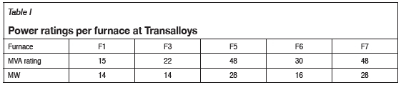
Transalloys is the largest producer of SiMn in Africa. Its smelter complex is based outside the town of eMalahleni, in the Mpumalanga Province of South Africa. Transalloys was commissioned in the mid-1960s as a high- and low-carbon ferrochromium plant based on the Perrin process. In 1967 the plant was converted to SiMn production because of constraints in the ferrochrome market (Basson, Curr, and Gericke, 2007; Bezemer, 1995). Today, the installed production capacity is 180 000 t of SiMn annually. Plant operations consists of five SAFs (see ratings in Table I), operating 24 hours a day, 365 days a year (including maintenance), involving 280 permanent employees, with up to 120 contract employees on site at any given time.
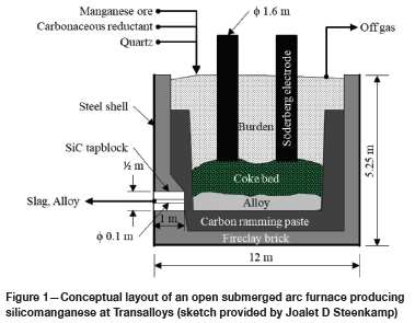
In the SAFs (see Figure 1 for a layout), SiMn is produced by carbothermic reduction of manganese-bearing ore. Manganese ore is sourced from the Kalahari Manganese Field in the Northern Cape Province. Quartz is sourced locally from South African producers. The main source of carbon is bituminous coal from South African coal mines, with imported coke also used. The specification of the SiMn alloy produced is 65% Mn, 16% Si, < 2% C, with Fe making up the balance. SiMn alloy is used as an alloying component to produce many different grades of steel.
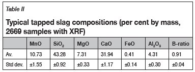
The SAFs are open to the atmosphere and process off-gas is combusted on top of the burden, from where it is cooled and cleaned through a baghouse system before venting to atmosphere. A mix of slag and alloy is cascade-tapped into alloy ladles and slag pots from a single tap-hole every four hours. Alloy and slag are separated post-tapping by cascade tapping and then removing slag from the alloy ladle with a slag scraper. Alloy is then layer cast in casting beds and slag is discarded onto slag dumps. The slag-to-alloy ratio is typically 1.0 to 1.3. Typical slag compositions are shown in Table II.
In the submerged arc furnace operation all three electrodes are covered by raw materials. Manganese enters the process as Mn2O3 and Mn3O4 and is prereduced in the upper layers of the furnace to MnO by CO gas permeating through the furnace burden. Final conversion of MnO to Mn and SiO2 to Si is facilitated by the coke bed below each electrode, as seen in Figure 1.
Managing the life-cycle
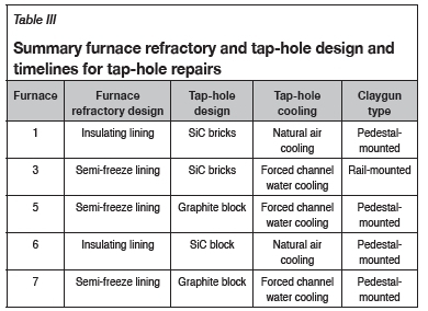
In this section the tap-hole designs are discussed. Table III provides a summary of the furnace refractory design and tap-hole design of each furnace.
A 'semi-freeze' lining at Transalloys refers to two concepts used in a single furnace. Different areas in the furnace are built either as a freeze lining or an insulating lining as follows.
> The sidewall areas around the tap-hole are graphite bricks with graphite tiles against the shell - this is the classic freeze lining concept.
> The rest of the sidewalls have a graphite tile against the shell and then a 60 Alumina brick as a working lining - a standard insulating lining.
> On the hearth two layers of carbon blocks are installed; but beneath these block are nine layers of high-alumina bricks (three layers each of 85 Alumina, 90 Alumina, and Tab Alumina) - a combination of freeze and insulating lining.
> On top of the two layers of carbon blocks a 600 mm carbon ramming is also installed - standard lining design for ferroalloy furnaces.
Why silicon carbide and carbon tap-holes?
Alloy produced at Transalloys is either C-saturated or SiC-saturated depending on the silicon grade of the alloy (see Figure 3) (Steenkamp et al., 2016).
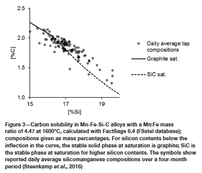
During excavation of a 48 MVA submerged arc furnace at Transalloys, two high-wear areas were found: the tap-hole area and the furnace hearth (Gous et al., 2014). Carbon-based refractory material formed the hot face refractory. Analysis of daily average tapped slag and metal compositions in the four months prior to excavation confirmed the potential for refractory wear through C dissolution in the metal (see Figure 3) and SiC formation by chemical reaction with SiO2 in the slag.
Design
All five furnaces have one single-level tap-hole. Metal and slag are tapped simultaneously every four hours. The furnace crucible is 3-4 m deep and the tap-holes are 200 mm above the hearth floor.
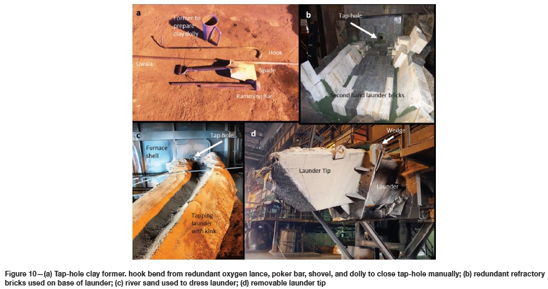
In 2008 only one furnace had a proper claygun and drill, and frequent tap-hole failures were experienced on all furnaces. Tap-holes were lanced open with oxygen and closed by hand using a 'dolly' (see Figures 10a and b). In an effort to improve tap-hole life two design philosophies were introduced as shown in Table III, mainly to address tap-hole problems. The first was a semi-freeze lining design where tap-hole cooling was crucial, and the second an insulating design using high-wear refractory. Both these designs stemmed from a need to ensure better tap-hole life as well as easy repair once a tap-hole failed.
Semi-freeze lining design
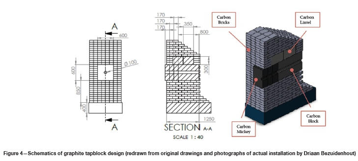
Furnaces 5 and 7 with the semi-freeze lining design are designed with a graphite tapblock. Figure 4 shows a typical graphite tapblock design consisting of a carbon block (600 mm χ 600 mm χ 800 mm), two graphite lintels (350 mm χ 300 mm x 800 mm), and three sacrificial mickeys (600 mm χ 600 mm χ 170 mm) on the working face with carbon bricks surrounding the tapblock.
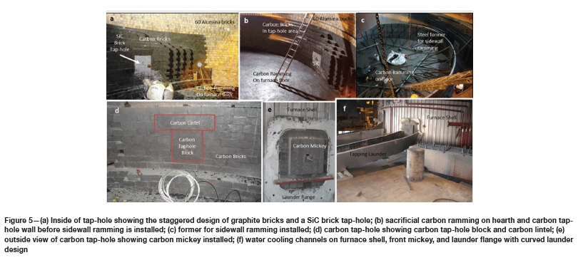
Figure 5a shows the staggered design on the sidewalls of furnace 3, allowing for optimal contact between the sidewall carbon ramming (Figure 5c) and the carbon bricks surrounding the tapblock. In the semi-freeze lining design the tapblocks, lintels, and mickeys are surrounded by carbon bricks (Figures 5b and d), allowing for maximum heat removal through external water cooling channels as shown in Figure 5f. The outside of a carbon tap-hole showing the installed mickey and the launder flange is shown in Figure 5e.
Figure 5b shows the installed carbon ramming on the furnace floor (800 mm thick). The carbon ramming is taken up to 200 mm below the tap-hole. When completed, a sidewall ramming is installed (800 mm wide) as shown in Figure 5c, covering the tap- hole graphite bricks. A drill depth of 2 m is required to open a tap-hole.
Figure 5f shows the tapping launder installed in position; notice a slight bend 2 m from the tap-hole. This allow for the tappers to lance and poke the tap-hole in a direct line with the tap-hole to prevent unnecessary damage to the carbon block. Figure 5d shows the front sacrificial mickey and flange as installed. The tapping launder is bolted onto the tap-hole flange.
Insulating lining design
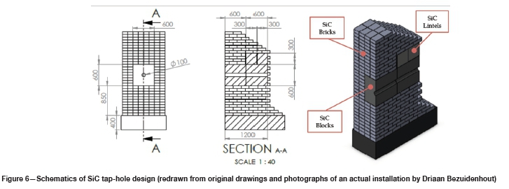
Furnaces 1 and 6 have an insulating refractory design with no external water cooling on the furnace shell. In this design the tap-hole is constructed with SiC blocks, SiC bricks, and a SiC lintel. Figure 6 shows a typical SiC tap-hole design consisting of a two SiC blocks (600 mm χ 600 mm χ 600 mm) and two SiC lintels (300 mm χ 800 mm χ 300 mm). Lintels are installed on the inside of the tap-hole to maintain the integrity of the sidewall. When the tapblock wears only the tap-hole block can be removed with careful demolition and then a new block inserted (similar to the carbon block installation in Figure 12).
Figure 7a shows the square block tap-hole design (furnace 1). The tapblock area consists of SiC bricks, whereas the rest of the furnace wall consists of SiO2/Al2O3 bricks. Figure 7b shows a staggered design of the bricks on the sidewall of Furnace 6, allowing for improved contact between the sacrificial carbon ramming wall (not yet installed) and the SiC bricks around the tap-hole.
Figure 7b shows the sacrificial carbon ramming on the furnace floor (600 mm thick). The ramming is taken up to 200 mm below the tap-hole. A steel pipe is inserted into the tap-hole in order to keep the tap-hole free from any obstructions and to facilitate the opening of the first tap after start-up. When completed, a sacrificial sidewall ramming is installed (600 mm wide) as shown in Figure 5c covering the SiC bricks forming the tapblock. A drill depth of at 1.8 m is required to open a tap-hole.
Figure 7d shows configuration of bricks on the outside of the tap-hole. The face plate and tap-hole flange where the tapping launder will be bolted onto are shown.
Hybrid design
Furnace 3 also has a semi-freeze lining design with external water cooling but with a SiC tap-hole. This tap-hole proved to be the most durable and only minor repairs were required in the eight years since the furnace was relined in 2008.
Tap-hole operations day-to-day
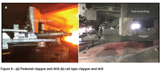
All furnaces are equipped with a separate hydraulic claygun and rill supplied by Dango & Dienenthal SA (Pty) Ltd. Figure 8a shows a pedestal-type claygun and drill, four of which are installed at Transalloys, and Figure 8b a rail-type claygun and drill, only one of which is in use. Drill bits used to open tap-holes are 76 mm in diameter and on average the drill depths are between 1.5 and 2 m. This section will focus on the opening of tap-holes, tapping of furnaces, closing of the tap-hole, and general tap floor operation and equipment.
Opening of tap-hole
Furnaces are tapped six times a day at fixed intervals of four hours. Each tap lasts approximately 30 minutes. A hydraulic tap-hole drill is used to drill open the tap-hole. The successful opening of a tap-hole depends largely on the proper closing after the previous tap. The tap-hole is considered to be properly plugged when the entire length of the tap-hole is filled with tap-hole clay and no slag or metal is frozen inside the tap-hole.
Before drilling the tap-hole, several important aspects need to be inspected and verified to reduce the risk of anything going wrong during the tapping process. Firstly, the drill bit is inspected to consider whether it is still sharp enough to 'cut' the tap-hole open as opposed to only 'pushing' the tap-hole open. Secondly, the air flow through the centre of the extension rod is tested to confirm there is adequate air flow to blow out the debris that is formed during the drilling process as well as to assist in the cooling of the drill bit and extension rod during drilling. It is important that the drilling debris be blown out of the tap-hole - if this is not the case the drill bit can get stuck. Thirdly, and most critical, the alignment of the drill with the tap-hole must be checked. If this alignment is not perfect a 'new' tap-hole will be drilled and at the end of the tap it will not be possible to close the tap-hole as the claygun will most probable not be aligned with the 'new' tap-hole
In case of the tap-hole not opening by drilling, an oxygen lance is used to open the tap-hole. Lancing of the tap-hole should be minimized due the fact that oxygen lancing reduces the life of the tap-hole considerably by oxidizing the refractory material.
Lancing the tap-hole should be carried out on the same level and in the same direction as the drill. This is to prevent the creation of secondary tap-holes, especially towards the back of the tap-hole. The design of the tap floor should be such that a person of average height holding the oxygen lance in a comfortable position should be able to lance horizontally. The launders are therefore slightly bent approximately 2 m from the tap-hole to enable the tapper to stand directly in front the tap-hole when lancing.
Only moderate oxygen pressure is required to lance through solidified slag and metal. If the pressure is too high the tap-hole wear will be increased dramatically due to increased oxidation. Additionally, due to the large amount of oxygen blown into the tap-hole there is a large amount of gas coming out of the tap-hole. This gas serves as a carrier gas for pieces of slag, alloy, or raw materials and can create dangerous situations with the particles moving as projectiles through the air posing the potential to cause serious injuries to persons standing on the tap floor.
However, when the oxygen pressure is too low the opening of the tap-hole is very time-consuming and slag and alloys are not blown out of the tap-hole effectively. The metal and slag then solidifies in the tap-hole channel and an excessive amount of oxygen will be required to open the tap-hole channel. Oxidation then occurs towards the front of the tap-hole. This wear can lead to rat-hole formation in the sidewall if the wear is not controlled properly. In this case the tap-hole cannot be drilled open. If drilling is attempted, utmost care must be taken that the drill bit does not deviate from the normal path when drilling into the metal, for example when the drill extension moves upwards in the tap-hole during drilling. This causes 'new' holes to be drilled and perforate the tapblock, reducing the life of the tapblock dramatically.
Once the tap-hole is open, a good practice to maintain a good flow of alloy and slag is to use a poker bar to keep the tap-hole open and the flow unrestricted. A poker bar is also a good tool to remove pieces of raw material or electrode that get stuck in the tap-hole.
Managing alloy and slag flow
If the alloy and slag flow is strong and uninterrupted, minimal intervention by the tappers is required. Occasionally the flow is slowed down by raw material mix obstructing the tap-hole. A poker bar is then used to clear the obstruction. Bigger obstructions like electrode pieces, bricks, and hardened tap-hole clay are sometimes difficult to remove with a poker bar. Then oxygen lancing is required to enlarge the tap-hole diameter to remove the obstacles. It is important to remove the obstacles continuously to ensure proper drainage of the furnace and to allow for proper closing of the tap-hole.
If obstacles are not removed from the tap-hole, the plugging of the tap-hole will be inefficient. At the next tap the tap-hole will be full of frozen alloy and slag and excessive lancing will be required. Excessive lancing increases tap-hole wear and in extreme cases the integrity of the tap-hole will be compromised when sidewall bricks start to collapse into the tap-hole.
The furnace is an integrated system and poor electrode management can adversely affect the life of a tap-hole, due to broken-off electrode pieces blocking the tap-hole and requiring excessive lancing. Operators need to understand that everything is integrated, therefore good electrode management is of utmost importance to prevent electrode tip losses that will cause blockages in the tap-hole.
Closing of tap-hole
For effective closing of the tap-hole after each tap the full length of the tap-hole should be filled with tap-hole clay to ensure proper contact between the tap-hole sidewalls and the new tap-hole paste. This will prevent the tap-hole from opening unexpectedly between taps due to pressure from the slag and metal inside the furnace pushing the tap-hole clay out of the tap-hole or leaking between the tap-hole clay and the tap-hole sidewall.
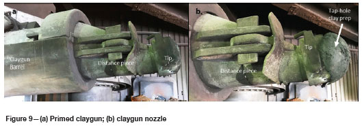
Clayguns should always be fully loaded and properly prepared before the tap-hole is opened, as shown in Figure 9a. The aim is for the clay to immediately push into the tap-hole as soon as the claygun piston starts pushing forward to displace metal and slag. The preparation of the claygun is aimed at preventing alloy from damaging the nozzle tip and to create a proper seal between the tap-hole and the claygun tip. The procedure for the proper preparation of the clayguns is described below.
During the loading and preparation of the claygun the tap-hole clay in the claygun barrel must be compressed to remove any voids. This is done by pressing the claygun against the tap-hole (when closed) and pushing the cylinder forward until clay is pushed out between the claygun tip and the tap-hole. This indicates that the tap-hole clay in the claygun is fully compressed. Omitting this increases the risk of burning the claygun nozzle when closing the tap-hole against a full stream of alloy. When closing the tap-hole against a full stream of alloy there will be a period when the cylinder is pushing clay forward but no clay is coming out of the nozzle and into the tap-hole, while voids in the barrel are being filled. Even if this is only for a few seconds when the furnace is tapping strongly the nozzle will burn and then the tap-hole will not be closed effectively. When the tap-hole is not closed the furnace will continue tapping, causing possible damage to downstream equipment and injuries to people. It is good practise to always be prepared for the worst case and this simple act performed in a disciplined manner can prevent damage when it is least expected. These types of emergencies can include launder penetration, ladle penetration or tapping over the launder, electrode breaks, or many other risks in the day-to-day operation.
As discussed, the alignment of the claygun and drill with the tap-hole is critical and must be checked on a daily basis. The nozzle tip needs to fit tightly around the centre of the tap-hole, ensuring that the full clay stream enters the tap-hole without squeezing out at the sides of the claygun tip.
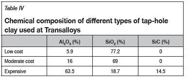
Three types of CTPV-free tap-hole clays are used at Transalloys, namely low cost (low quality), intermediate cost (standard quality), and high cost (high quality). A summary of the chemical compositions of the different types of clay is given in Table IV. Only the intermediate- and high-cost types of clay can be used to rebuild a damaged or worn tap-hole. To control operational costs low-cost clay is used in normal day-to-day operations with the expectation there will be some wear of the tap-hole. Good tap-hole practise can delay this wear. The tap-hole clay quality affects not only the tap-hole integrity, but all the aspects around the tap-hole operations. When it is noted the tap-hole is starting to wear beyond a certain limit a switch will be made to the intermediate-cost tap-hole clay with the aim of restoring the tap-hole condition. If serious tap-hole problems occur, i.e. when bricks in the tap-hole fall out, the expensive tap-hole clay will be used to repair the damage. A practical approach to tap-hole management must consider the cost of the tap-hole clay and the integrity of the tap-hole.
Tap floor activities
Launders are cleaned after every second tap and re-dressed with river sand (see Figure 10g). Launder sand protects the carbon ramming on the launder and also makes it easy to remove the slag and alloy from the launder.
Figure 10a shows some of the typical launder cleaning tools used on a tap floor. A bent oxygen pipe is used to remove alloy and slag buildups after they have been loosened with a steel roundbar. In the case of the claygun not being operational a dolly is used to close the tap-hole manually. Figure 10a also shows a former used to create a tap-hole clay plug to be used when closing the tap-hole.
The steel launder is normally lined with used refractory bricks of any quality used at Transalloys (alumina, SiC, or carbon bricks, Figure 10b), then covered with carbon ramming material and finally covered with a layer of sand (see Figure 10c). The sand makes the cleaning of the launder easier in that it is easier to insert a steel 'gwala' below the metal/slag scull through the sand layer and lift the skull out of the launder.
Launders are angled to allow for lancing and poking to be conducted parallel with the tap-hole. A launder tip is attached to the front end of the launder (see Figure 10d). High wear-resistant castable refractory is used in the launder tip to withstand the eroding forces, especially from the alloy. The launder tip is fastened to the launder with wedges to allow for movement or a default line in case a crane driver accidentally knocks the launder tip when removing or placing the ladle. No damage to the launder or launder flange at the furnace shell will occur if this happens. Worn-out launder tips are replaced every three to four months to prevent alloy from damaging the top ring of alloy ladles.
Tap-hole and hearth maintenance programme
Monitoring of furnace hearth temperatures, visual inspections of tap-holes, drill depth, tap-hole diameter, and tapping conditions are used to determine a maintenance and tap-hole repair schedule.
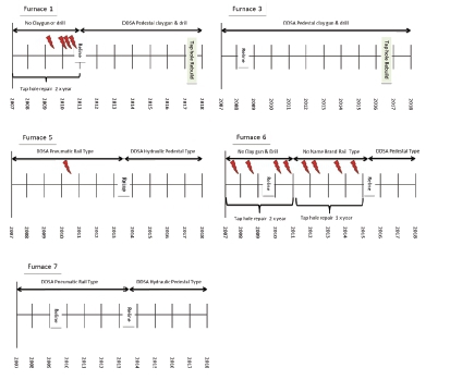
Previous excavations and lining failures indicated that the most problematic area in the SiMn production process is the wear of the hearth refractory in the clover area (PCD) under the furnace electrodes. Subsequently, all furnaces were equipped with several hearth thermocouples to monitor hearth temperatures. Table V shows typical life-cycles of relines and tap-hole repairs for each furnace at Transalloys. Time intervals listed in Table V may be shorter in cases of catastrophic lining failures or excessive O2 lancing that will reduce the lifetime of a tap-hole. Long downtimes (in excess of 3 months) can also lead to lining failures due to uneven contraction and expansion of the hearth and sidewall refractories.
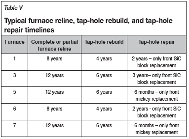
Telltale signs that indicates that a tap-hole rebuild is imminent are the following: refractory bricks coming out of tap-hole, furnace tapping raw material mix at regular intervals, increase in tap-hole clay usage, and tap-hole being drilled open within less than 1 m of drill penetration. Tap-hole life can be extended by using expensive high-quality clay containing SiC (see Table III). This can buy time to properly plan for a tap-hole rebuild or repair.
A complete furnace reline involves a total excavation of the furnace and replacement of all refractories, including sidewall, hearth, and tap-hole. A partial reline requires only the replacement of the sacrificial carbon ramming on the furnace floor. This will also allow for the repair of the tap-hole from the inside of the furnace. Excavation of the furnace burden and subsequent visual inspection of the furnace lining will determine the extent of the rebuild or repair.
Tap-hole rebuild
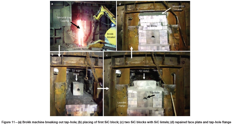
Figure 11 shows the steps in the rebuilding of a SiC tap-hole. A rebuild is completed in four days (from furnace switch-out to first tap), including the warming up of the tap-hole refractories.
Before switching out the furnace for a tap-hole rebuild the furnace needs to be melted down as far as possible, which will reduce the amount of loose burden that has to be removed from the tap-hole. The sequence of events after the last tap has been made and the furnace is switched out is as follows: cooling down for 12 hours, removal of tapping launder, installation of a working platform in front of the tap-hole, removal of tap-hole face plate to expose tap-hole refractories, breaking out of tap-hole refractories with a Brokk machine, and allowing the remaining molten slag and metal to drain from the furnace (see Figure 11a). During the breaking out of the refractory and removal of loose burden and solidified slag, water cooling is applied to increase the rate at which the tap-hole area is cooled down. Final breaking out of tap-hole bricks is done carefully with a jackhammer to expose undamaged tap-hole bricks to establish a clean surface to tie-in the new refractory bricks.
Figures 11b, 11c, and 11d show the installations of the SiC -blocks, lintels, and SiC bricks in furnace. The bricks below the block are started from a solid foundation or good floor. After the rebuild of the tap-hole is completed, the faceplate and launder flange are replaced. A steel pipe is placed in the tap-hole and only plugged with a small piece of tap-hole clay at the hot face of the pipe to assist with the opening of the first tap after start-up. After the launder is replaced, the tap-hole bricks are extended into the launder and then rammed with carbon material. It is of utmost importance to check the alignment of the claygun and drill after a tap-hole rebuild.
In order for the newly build tap-hole to cure and bake properly, the furnace is switched in in STAR mode to allow for the gradual heating-up of tap-hole refractories over a 24-hour period. The same methodology is followed with the rebuild of a graphite block tap-hole.
Tap-hole repair
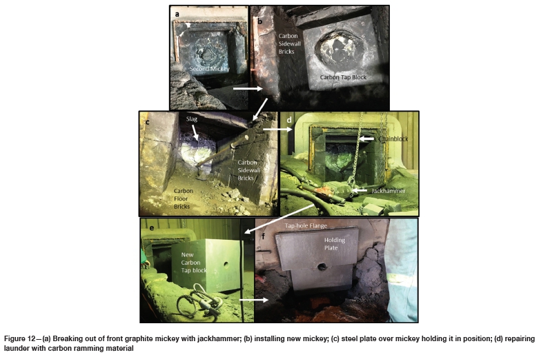
Under normal conditions, repairing a graphite tapblock entails only the replacement of the front sacrificial mickey. This can be done on an eight-hour planned shutdown. The launder sand and refractory materials in the launder are cleaned out with a jackhammer and shovel to expose the full mickey.
The old mickey is then removed by breaking it out with a jackhammer (Figure 12a) and replaced with a new micky (see Figure 12b). Removal of the first mickey allows for inspection of the second mickey and if required it can also be replaced.
After the mickey has been replaced, a 20 mm steel plate is installed over the mickey to keep it in position (see Figure 12c). Carbon ramming material is then used to line the launder up to the tap-hole again (see Figure 12d). A new mickey does not require warming-up before it can be used.
The same methodology is used when replacing the cold face SiC block. The estimate time for only replacing the cold face SiC-block is 12 hours.
Start-up after maintenance and repair
The commissioning of a furnace after a major reline normally takes 7 days. The megawatt input per hour is regulated to allow heat soaking of refractories and carbon ramming, to drive off volatiles and moisture, and to allow for expansion of the refractories. Because the furnaces are open furnaces the refractories cannot be heated with gas and the warming-up is carried out with electricity using the furnace transformers in STAR mode configuration until the first tap is made.
Gradual heating-up of furnace after a long shutdown, more than three months, is also important to allow for slow expansion of the refractories. This type of warm-up is completed in three to five days.
Conclusions
At Transalloys the furnace linings are of an insulating and semi-freeze lining design. SiC blocks and graphite blocks are used.
Procedures and systems have been established to ensure an optimum life-cycle of furnace linings, tap-holes, and auxiliary tapping equipment. All furnaces are equipped with clayguns and drills. Proper plugging of tap-holes and only selective O2 lancing has extended the tap-hole lives noticeable. Well established heating and warming-up schedules for newly build furnace linings and tap-holes allows for optimum drying, baking, and expansion of refractory material.
Acknowledgements
This paper is published by permission of Transalloys and Mintek. The contributions of our colleagues are gratefully acknowledged.
References
BAssoN J., CuRR T.R., and Gericke, W.A. 2007. South Africa's ferro alloys industry -present status and future outlook. Proceedings of Infacon XI: Innovation in Ferroalloy Industry, New Delhi, India, 18-21 February 2007. Indian Ferro Alloy Producers Association. pp. 3-24. [ Links ]
Bezemer, K. 1995. The silicomanganese production process at Transalloys, Proceedings of INFACON VII, TTondheim, Norway, 11-14 June 1995. Tveit, H., Tuset, J.K., and Page, I.G. (eds). Norwegian Ferroalloy Producers Research Organization (FFF). pp. 573-580. [ Links ]
Gous, J., Zietsman, J., Steenkamp, J., and Sutherland, J. 2014. Excavation of a 48 MVA silicomanganese submerged-arc SiMn furnace in South Africa - Part I: Methodology and observations. Proceedings of the 5th International Symposium on High-Temperature Metallurgical Processing. The Metals, Minerals and Materials Society, Warrendale, PA. pp. 255-269. [ Links ]
Steenkamp, J.D., Sutherland, J.J., Hayman, D.A., and Muller, J. 2016. Tap-hole life-cycle design criteria: a case study based on silicomanganese production. JOM, vol. 68, no. 6. pp. 1547-1555. [ Links ]
 Correspondence:
J.J. Sutherland
Email: Kobuss@transalloys.co.za
Received: 12 Apr. 2019
Revised: N/A
Accepted: N/A
Published: June 2019

