


Serviços Personalizados
Artigo
 Inglês (pdf)
 Artigo em XML
 Referências do artigo
Indicadores

Links relacionados
-
 Citado por Google
 -
 Similares em Google
Compartilhar

 Permalink
Journal of the Southern African Institute of Mining and Metallurgy
versão On-line ISSN 2411-9717
versão impressa ISSN 2225-6253
J. S. Afr. Inst. Min. Metall. vol.119 no.6 Johannesburg Jun. 2019
http://dx.doi.org/10.17159/2411-9717/669/2019
FURNACE TAPPING
Wear analysis of tap-holes at two ferrochromium production furnaces
J.D. SteenkampI, II
IMintek, Randburg, South Africa
IIUniversity of the Witwatersrand, South Africa
This paper was first presentedat the Furnace Tapping 2018 Conference, 15–16 October 2018, Nombolo Mdhluli Conference Centre, Kruger National Park, South Africa.
SYNOPSIS
In July of 2016 and June 2017, major tap-hole repairs were carried out during the annual shutdown of two 63 MVA submerged arc furnaces producing ferrochromium in South Africa. The hot excavations of the tap-holes allowed for a study of the wear profiles. Subsequent thermodynamic calculations allowed for the quantification of the potential for chemical reaction between refractory and slag or alloy contributing to wear in the tap-hole area. Results from both wear profiling and thermodynamic calculations are reported here.
Keywords: ferrochromium furnace, tap-hole, wear analysis, refractory corrosion.
Introduction
Ferrochrome (FeCr) is an essential alloy in the production of stainless steel (Gasik, 2013). In 2017, 11.7 Mt of FeCr was produced (Pariser et al., 2018.). The main producers were China (39%), South Africa (29%), Kazakstan (12%), and India (8%).
A number of grades of FeCr are available to producers of stainless steel, including high-carbon ferrochrome (HCFeCr) (Gasik, 2013). HCFeCr typically contains 60-70% Cr and 4-6% C (Basson and Daavittila, 2013). When the chromium content is lower (50-55% Cr) and the carbon content higher (6-8% C), it is referred to as charge chrome. Charge chrome is typically produced in South Africa due to the grades of ore available.
FeCr is produced in submerged arc furnaces (SAFs) and in open arc furnaces (Mc Dougall, 2013) by carbothermic reduction of oxide raw materials. In a SAF the electrode tips are submerged in a porous charge mix. In FeCr production, the electrical energy is mainly liberated by resistive heating of the wet coke bed (Barker et al., 2007; Steenkamp et al., 2017). Thermally conductive lining design philosophies are typically applied in SAFs producing FeCr (Steenkamp, Denton, and Hayman, 2017; Coetzee, Duncanson, and Sylven, 2010; Coetzee et al., 2010).
In July of 2016 and June of 2017, major tap-hole repairs were carried out during the annual shutdown of two 63 MVA SAFs producing FeCr in South Africa. The hot excavations of the tap-holes allowed for a study of the wear profiles. Both SAFs were operated on the same site, by two different operating crews, using the same raw materials. The major difference between them was that the SAF excavated in 2016 was an open SAF (referred to as Furnace A) and the one excavated in 2017 was a closed SAF (referred to as Furnace B). In an open SAF, a gap exists between the top of the steel shell and the roof, with the top of the burden being open to the atmosphere and the CO-rich off-gas being combusted as it escapes. In a closed SAF, the roof is attached to the steel shell and the CO-rich off-gas is collected from an offtake on the roof for further treatment and used in downstream processes.
The paper presented here reports the macro-scale observations on refractory wear for the two SAFs, and studies the potential for chemical wear of refractory by slag and alloy as a potential contributing factor to the tap-hole wear observed.
Background
Refractory wear mechanisms associated with the tap-hole region
The refractory wear mechanisms reported in the literature for SAFs are densification, spalling, erosion, and corrosion.
Densification (infiltration) is caused by slag or metal infiltrating pores and/or reacting with refractory (Hancock, 2006; Inada et al., 2009).
Spalling is caused by thermal stress due to a high thermal gradient across a single refractory body (Hancock, 2006). Refractory material on the hot face fractures and breaks away due to densification and/or thermal stress (Coetzee, Duncanson, and Sylven, 2010).
Erosion (abrasion) is caused by slag, metal, and solid material abrading refractory (Hancock, 2006; Duncanson and Toth, 2004).
Corrosion (chemical wear) is caused when the system is not at equilibrium. Slag, metal, or a flux will dissolve the refractory components it is not saturated with and/or chemically react with them (Hancock, 2006). Corrosion always begins with the interaction of some minor (binder phase) or major (aggregate) constituents of the refractories with the liquid slag or metal (Hubble, 1999). Similarly, gas reactions between carbon refractory materials and CO2, H2O, and O2 (pure and in air) have been reported, as summarized by Nelson and Hundermark (2016).
Tap-hole wear is a complex phenomenon (Nelson and Hundermark, 2016) and although oxygen lancing is commonly seen as the main contributor to tap-hole wear (Erwee, Reynolds, and Zietsman, 2016), studying the potential for other wear mechanisms (i.e. the potential for corrosion of tap-hole refractory by slag or alloy during tapping) assists in the selection of refractory materials used to construct tapblocks to minimize the potential for wear.
Refractory design
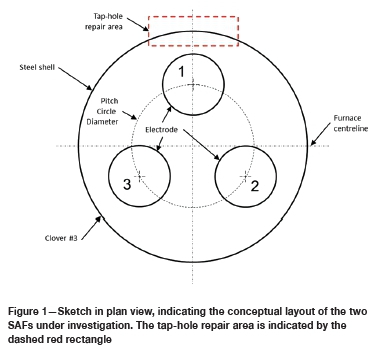
The SAFs under investigation were of circular design, with inner diameters of the steel shells at 13.7 m and heights (from the cold face of the hearth refractories to the top of the sidewalls) approximately 5.5 m. The three S0derberg electrodes (1.55 m in diameter) were positioned equilaterally with one, single-level tap-hole positioned at electrode 1 (referred to as the 'tap electrode') -see Figure 1. For both shutdowns, preparations were made for 3 χ 3 m repair of the refractory material in the tap-hole area. In the case of Furnace A, the sidewall at clover no. 2 was also repaired, and in the case of Furnace B, the sidewalls at both clover no. 2 and clover no. 3 were repaired.
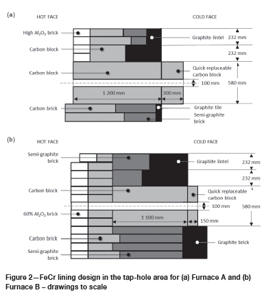
The refractory designs in the tapblock areas are indicated in Figure 2. In both designs, a single carbon block formed the tapblock on the inside of the steel shell. On the cold face of the tapblock a smaller replaceable block (the quick-replaceable carbon block in Figure 2) was installed. In the case of Furnace B, the tapblock was extended further into the furnace by the installation of a row of carbon bricks towards the hot face of the tapblock. The hot face of the carbon bricks was protected by a layer of sacrificial alumina bricks. Towards the cold face, semi-graphite bricks and graphite bricks or tiles were installed. Semi-graphite bricks have artificial graphite as aggregate and petroleum pitch or coal tar as binder. No copper coolers were installed in the tap-holes, and the steel shells around the tap-holes were cooled with water - thin-film cooling in the case of Furnace A and forced channel cooling in the case of Furnace B.
Tapping practice
With the furnaces having only one single-level tap-hole, slag and alloy were tapped simultaneously. Each furnace was equipped with a pedestal-type drill-and-claygun. Furnace A was tapped eight times a day on average with a standard deviation of 1 (calculated from a daily production data-set for 1 January 2014 to 30 June 2016). Similar information for Furnace B was not available.
Operational practices included the sampling of slag and alloy at each tap. The slag sample was taken with an oxygen lance in the launder because oxygen lances were available freely on the tap floor. The alloy sample was taken in the alloy ladle with a 'lollipop-sample dipstick' or also in the launder. Slag and alloy compositions were determined by powder X-ray fluorescence (XRF). The carbon content of alloy samples was determined by combustion (LECO).
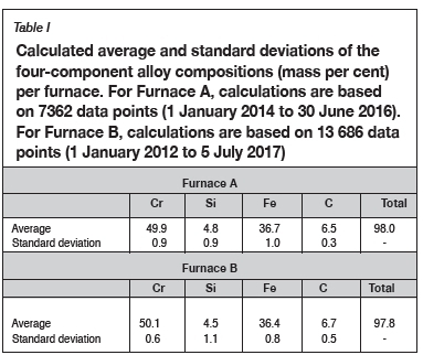
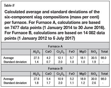
The calculated averages and standard deviations in chemical compositions of tapped slag (six main components only) and alloy (four main components only) were calculated for the periods 1 January 2014 to 30 June 2016 for Furnace A and I January 2012 to 5 July 2017 for Furnace B. The data-sets were not filtered for outliers. The alloy compositions are reported in Table I, and slag compositions in Table II.
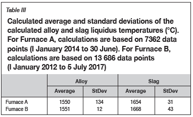
Tap temperatures were not measured on either of the SAFs. Liquidus temperatures were calculated by the plant operating system based on the chemical compositions of the slag and alloy. The calculations used to determine these liquidus temperatures were not made available to the author. The calculated averages and standard deviations in liquidus temperatures of the slag and alloy are summarized in Table III. Data-sets for the same periods were used and were again not filtered for outliers.
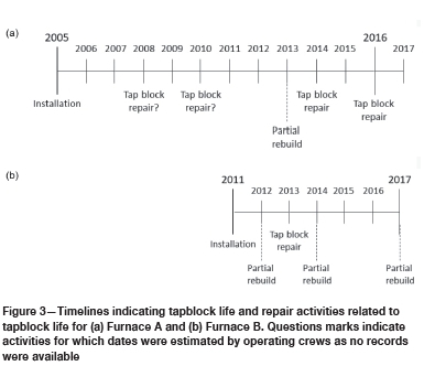
Tapblock life
The tapblock life of Furnace B was significantly shorter than for Furnace A - see timelines in Figure 3. During initial installation, the SAFs were fully relined. During a tapblock repair only the tapblock is replaced, while during a partial rebuild both the tapblock and a section of the sidewall are replaced. The linings were installed in 2005 in Furnace A and 2011 in Furnace B. In Furnace A, the tapblock was replaced during a repair on average every 2-3 years. In Furnace B, the tapblock was replaced either during a repair or during a partial re-build, on average every 18 months.
Method
Furnace preparation prior to switch-out
In both instances, when the SAFs were prepared for the partial rebuild, the intention was for the SAFs to be emptied by melting down the burden and tapping through the tap-hole. For a specific SAF, the night prior to switch-out, feed to the furnace was stopped and power input maintained. The melt-out was monitored by managing the furnace power input (MW) and specific energy consumption (MWh per ton alloy tapped). During such an operation, not only the burden (consisting of ore, flux, reductant, slag, coke bed, and alloy) will be melted and tapped, but also any freeze lining that formed during normal operation of the furnace.
Tap-hole wear study on the macro-scale and wear profiling
For the macro-scale investigation, photographs were taken of the refractory in situ. A CANON EOS 30D camera and CANON zoom lens (EF 75-300 mm F4-5.6) installed on a tripod and triggered by remote trigger was used. The camera settings for aperture and shutter speed were adjusted manually based on the lightmeter readings on the camera. Lighting was provided by free-standing floodlights and no flash was applied. The refractory thickness was measured using a tape measure.
Thermodynamic calculations approach
The containment philosophy for the two furnaces was based on a conductive lining design (Steenkamp, Denton, and Hayman, 2017). In a conductive lining design where a layer of process material is frozen on the hot face of the refractory lining, chemical compatibility between refractory material and liquid process material is not important as the intention is for a frozen layer of process material to form at the interface between the liquid process material and the refractory material. Due to the dynamic conditions in the tap-hole area, the probability of a stable freeze lining forming is very low, as the excavation of these two tapblocks clearly illustrates. The probability that during tapping the tapblock refractory material is in contact with liquid alloy or slag is very high. Therefore, the potential for chemical wear of the tapblock refractory by FeCr alloy or slag was determined by thermodynamic calculation.
The Equilibrium model in FACTSage 7.2 was applied in the thermodynamic calculations (Bale et al., 2002). Depending on the type of calculation the FToxid and/or SGTE and FACTPS databases were selected. Default gas and solids were selected as pure species. Duplicates were suppressed with the order of preference being FACTPS, FToxid, and SGTE databases.
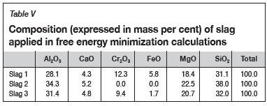
The composition of the alloy used in the calculations is presented in Table IV, and slag in Table V. In all calculations, initial conditions were not specified.
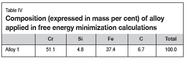
The alloy composition in Table IV is the average of the normalized alloy compositions for Furnace A and Furnace B presented in Table I.
The slag compositions in Table V were determined as follows:
> Slag 1 is the average of the normalized slag compositions for Furnace A and Furnace B presented in Table II. These analyses showed elevated levels of Cr2O3 and FeO due to the presence of entrained alloy as well as partially altered chromite (Bergmann, Govender, and Corfield, 2016). Using the results in thermodynamic calculations will result in levels of wear that are artificially attributed to the reduction of FeO, and to a lesser extent reduction of Cr2O3.
> Slag 2 is Slag 1 without the Cr2O3 and FeO present and normalized. The purpose was to determine if reduction of any of the other phases present in the slag could result in refractory wear.
> Slag 3 is Slag 1 excluding the presence of alloy phases, based on a study done by Bergmann, Govender, and Corfield (2016).
For the purpose of the calculations, the composition of the carbon block was assumed to be 100% C as the actual composition of the refractory was not known. As an alternative, refractory material consisting of 100% SiC was considered due to the use of SiC-based refractory material as a tapblock in silicomanganese production (Steenkamp, Pistorius, and Muller, 2016).
The temperature range was selected based on the calculated liquidus temperatures of the tapped alloy and tapped slag presented in Table III. For alloy, the temperature range 1450-1650°C at 50°C intervals was selected, and for slag, 1550-1750°C at 50°C intervals. In all instances, results were calculated at the temperatures selected as well as at temperatures where phase transformations occurred, i.e. normal+transitions was selected.
A pressure of 1 atmosphere was selected, although the ambient pressure at the plant is typically 0.85 atmospheric.
Equilibrium phase distributions of alloy and slag on their own
To obtain an understanding of the system under investigation, the equilibrium phase distributions of slag and alloy were calculated. For slag the FToxid and FACTPS, and for the alloy the SGTE and FACTPS databases were selected. For alloy, all solution phases were selected except for SGTE-DIAM. For slag, all solution phases were selected except for FToxid-OlivB and FToxid-Oliv? (one of the solution phases available in the FToxid database).
Equilibrium phase distribution of alloy reacted with refractory
The equilibrium phase distribution of the reaction products for the reaction of 50 g of alloy with 50 g of refractory was then calculated as a function of temperature. The aim was to identify the potential for chemical reactions between refractory and alloy, the types of reactions that would occur, and the temperatures at which these reactions would occur. The SGTE and FACTPS databases were selected. All solution phases were selected except for SGTE-DIAM. For pure solids, Cr4C formation was suppressed to allow for the formation of carbide solution phases.
Equilibrium phase distribution of slag reacted with refractory
Subsequently, the equilibrium phase distribution of the reaction products for the reaction of 50 g of slag with 50 g of refractory was calculated as a function of temperature. The aim was to identify the potential for chemical reaction between refractory and slag, the types of reactions that would occur, and the temperatures at which these reactions would occur. The SGTE, FTOxid, and FACTPS databases were selected. All solution species were selected except for FToxid-OlivB, FToxid-oliv?, and SGTE-DIAM. For pure solids Cr4C formation was suppressed.
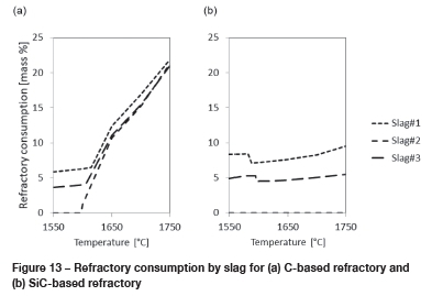
Refractory consumption
Finally, refractory consumption as a function of temperature was calculated according to Equation [1].
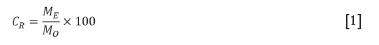
where:
CR: Refractory consumption, in mass per cent
MO: Original mass of refractory, in grams
ME: Mass of refractory in equilibrium with alloy or slag at a specific temperature, in grams
Results and discussion
Plant-based observations
The tap-hole area of Furnace A was in a much better condition than that in Furnace B, as seen in Figure 4a compared to Figure 4b. The photographs in Figure 4 were taken after removal of the tap launders.
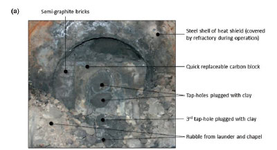
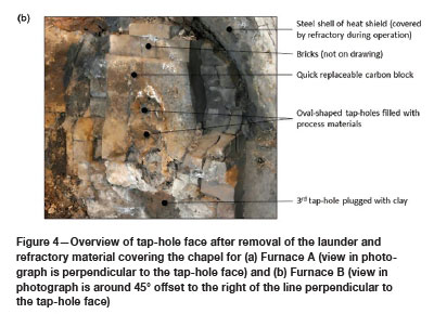
At both SAFs, the quick-replaceable carbon blocks were installed in an area referred to as the chapel, which was named after the shape of the protective heat shield around this area. In Figure 4, parts of the steel shells of the protective heat shields are clearly visible as the refractory materials which cover them during operation were removed by the time the photographs were taken. In Figure 4a the rubble generated during the removal of the launder and the refractory from the protective heat shields is still visible.
The quick-replaceable carbon blocks on both SAFs had very large, oval-shaped tap-holes as seen in Figure 4. The tap-hole in Furnace A was filled with tap-hole clay (Figure 4a) and in Furnace B with slag and alloy (Figure 4b). For each SAF, the oval-shaped tap-hole appeared to consist of two distinct tap-holes, as is clearly visible in Figure 4a. Below the quick-replaceable carbon block a third 'tap-hole' was visible, again seen more clearly in Figure 4a. These observations indicate that even though the tap-hole design philosophy was based on one single-level tap-hole, normal operations require two tap-hole levels and emergency operations a third. Therefore the tap-hole life-cycle (Steenkamp et al., 2016) was not taken into account when the refractory design was undertaken. Furnace designers will probably argue that operations were not conducted properly, but these two SAFs were operated by two different operating crews and the fact that the observation was made on both SAFs is probably an indication that tapblock life could be improved by a design that allows for the need for three tap-hole levels.
The dimensions of the quick-replaceable carbon blocks were determined by measuring tape, and those of the oval-shaped tap-hole by dimensional analysis (see Figure 5). In both cases, the oval-shaped tap-holes covered in the order of 50% of the surface area of the quick-replaceable carbon blocks. In comparison, for a new quick-replaceable carbon block the tap-hole area is only 10% of the total area.
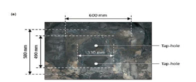
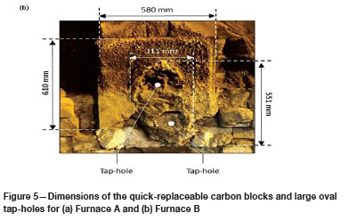
Another observation made from Figure 5 is that the quick-replaceable carbon block in Furnace B was installed at a 90° offset from the original design. In Figure 5a the long end of the block is in a horizontal position and in Figure 5b in a vertical position. The deviation is attributed to the tapblock wear in Furnace B being much more significant than in Furnace A, as can be seen in Figure 6.
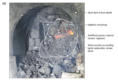
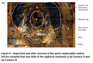
Upon removal of the quick-replaceable carbon blocks, very little of the original tapblock remained for Furnace A (Figure 6a) and none for Furnace B (Figure 6b). The areas where the tapblocks were supposed to be were filled with process material. In Furnace A (Figure 6a), the process material consisted mainly of coke bed, in other words slag and carbonaceous reductant. In Furnace B (Figure 6b), the process material consisted of a coke bed and tap-hole clay mixture towards the top and alloy at the bottom. In Figure 6b, the tap-hole clay used to plug the tap-hole is clearly visible.
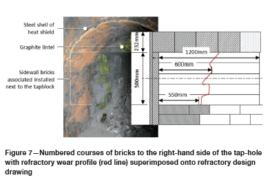
For Furnace A, a wear profile of the refractory surrounding the tapblock could be determined by manual measurement once the refractory around the tapblock cooled, allowing access. Measurements were done using a tape measure and the results were superimposed onto the design drawing - see Figure 7. As can be seen from the drawing, only in the order of 50% of the sidewall refractory surrounding the tapblock remained. The wear observed was probably a result of a combination of sidewall refractory wear associated with each of the clovers and wear associated with the tapping of liquid slag and alloy through the tap-hole and associated lancing activities. For Furnace B, a wear profile could unfortunately not be determined due to time constraints.
Thermodynamic calculations
In the sections below, the phase distributions for specific conditions are presented as a function of temperature. The conditions were alloy or slag on their own, and slag or alloy in combination with C or SiC refractory.
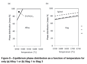
Equilibrium phase distributions of alloy and slag on their own
In Figure 8, the results for alloy and slag only are presented. At temperatures below 1500°C a solid iron-containing chrome carbide is present (see Figure 8a). Above 1500°C the alloy will be 100% liquid. In the slags, a spinel (Cr, Fe, Mg, and Al-rich) and a liquid slag phase are present in the temperature range 1550°C to 1750°C. As the temperature increases, the liquid slag phase increases as expected. The slag:spinel ratios for Slag 1 and Slag 3 are very similar over the temperature range, ranging between 2.3 and 4.5. For Slag 2, the ratio is higher over the temperature range and ranges between 3.9 and 7.8. The lower spinel content in this slag is expected due to the absence of spinel-forming Cr and Fe.
Equilibrium phase distribution of alloy reacted with refractory
In Figure 9, the results for alloy in contact with refractory are presented.
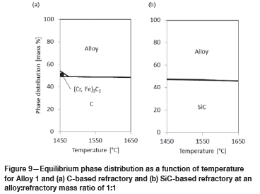
For alloy in contact with C-based refractory, three phases are present: the C-based refractory, the liquid alloy, and an iron-containing chrome carbide with an increased carbon content (metal-cation-to-carbon ratio is 1.5 for the carbide formed in Figure 9a, compared to 2.3 for the carbide formed in Figure 8a). This carbide phase is present only at temperatures below 1475°C. The slight reduction in the amount of C-based refractory is either due to the formation of (Cr, Fe)3C2 or to solution into the liquid alloy.
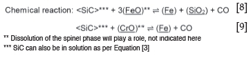
For alloy in contact with SiC-based refractory, only two phases are present: the SiC-based refractory and the liquid alloy. In the temperature range under investigation, the reduction in the amount of SiC-based refractory is due to solution into the liquid alloy.
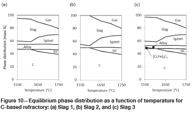
From these results, it can be concluded that two potential corrosion mechanisms apply: chemical reaction or dissolution, described by the following three chemical reactions:
where:
<M> depicts species present as a solid phase
(M) depicts species present as a liquid phase
M depicts species in solution
M depicts species present as a gas phase.
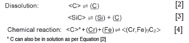
Equilibrium phase distribution of slag reacted with refractory
In Figure 10, the results for slag in contact with C-based refractory are presented.
For all three slags, spinel and liquid slag phases are present in the temperature range under investigation. Interestingly enough, the slag:spinel ratio initially increases and then decreases with temperature in all three instances.
For all three slags, SiC forms as a reaction product at around 1600-1650°C. The amount of SiC formed is greatest for Slag 2 (see Figure 10b).
In the slags with Cr and Fe present (Slag 1 and Slag 3), liquid alloy forms in the temperature range under investigation. For Slag 3, the iron-containing chrome carbide with metal-cation-to-carbon ratio of 2.3 observed in Figure 9a also forms at temperatures below 1590°C.
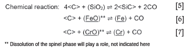
From these results, it can be concluded that one potential corrosion mechanism applies: a chemical reaction - described by Equations [5] to [7]:
In Figure 11, the results for slag in contact with SiC-based refractory are presented.
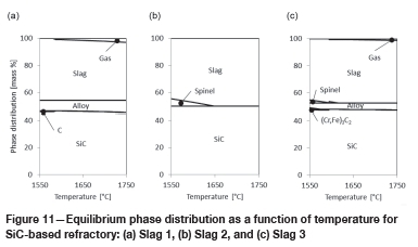
The liquid slag phase is present in all three cases in the temperature range under investigation. Only for Slag 2 and Slag 3 are there spinel slag phases, and only at temperatures below 1600-1650°C.
For Slag 1, C forms as a reaction product below 1580°C, and for Slag 3 SiC forms below 1600°C.
In the slags with Cr and Fe present (Slag 1 and Slag 3), liquid alloy forms in the temperature range under investigation. Gas also forms in increasing amounts as the temperature increases. For Slag 2 no gas forms as no Cr2O3 or FeO are present in the slag.
From these results, it can be concluded that one potential corrosion mechanism applies: chemical reaction, described by Equations [3] and [4] above, and Equations [8] and [9]:
Refractory consumption
From the results presented in Figure 9, the main corrosion mechanism responsible for the wear of C- or SiC-based refractory by FeCr alloy is the dissolution of the refractory into the alloy. As can be seen in Figure 12, the potential for SiC-based refractory to dissolve into alloy is greater than for C-based refractory.
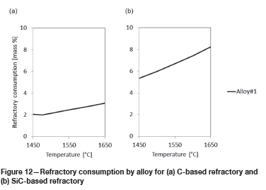
From results presented in Figure 10 and Figure 11, the main corrosion mechanism responsible for the wear of C- or SiC-based refractory by FeCr slag is chemical reaction. This includes the reduction of CrO and FeO in the slag to form alloy, and the reduction of SiO2 in the slag to SiC.
For Slag 2, where CrO and FeO are absent, only SiC formation applies and only for C-based refractory material. For Slag 1 and Slag 3, both alloy and SiC formation apply. In alloy formation, dissolution of the spinel phase into the slag to supplement the CrO and FeO, reduced according to Equations [6] to [9], plays a role. To what extent the reaction kinetics will allow for the dissolution to occur during tapping is a matter for further investigation. Based on the refractory consumption calculations presented in Figure 13, C-based refractory as a tapblock material will perform similarly to SiC-based refractory at temperatures below 1600°C. At 1600°C to 1650°C, SiC formation will result in increased consumption of C-based refractory, and at temperatures exceeding 1650°C the SiC-based refractory will outperform the C-based refractory. To what extent lancing affects the temperature and slag composition in the tapblock, and how this contributes to the mechanisms observed, will be interesting to understand.
Conclusions
> In the furnaces excavated, the tap-hole was one of two high refractory wear areas, with the others being the sidewalls around the clovers of electrodes 2 and 3. The life of the tapblock in the open SAF was on average double that in the closed SAF. The results presented here do not explain the difference, and a similar study on the potential effect of refractory corrosion by gas phases present in fully enclosed SAFs will be useful.
> In both furnaces excavated, very little (if any) of the tapblocks remained and the SAFs were basically operated only with the quick-replaceable carbon block as the tapblock.
> Thermodynamic calculations indicate that both alloy and slag had the potential to corrode the tapblocks, either through dissolution or through chemical reaction. For the alloy, the main mechanism is related to dissolution of C or SiC into the alloy. For slag, chemical reactions between CrO, FeO, and SiO2 in the slag and refractory are the main mechanisms with alloy, SiC, and gas the reaction products formed. At temperatures below 1650°C, C-based refractory will potentially be the best choice in tapblock refractory, while above this temperature a SiC-based refractory would be preferred.
> Laboratory-scale investigations to confirm these observations will be useful from an applied research perspective, and to study the reaction mechanisms involved from a fundamental research perspective.
> Further investigation into the effect of the lancing process on tap-hole wear would add significant value to the understanding of tap-hole wear, both in terms of the effect of the reaction between the refractory and oxygen in the gas phase and also in terms of the changes in chemical composition of the slag and the temperature changes in and around the tapblock.
Acknowledgements
The support of management and personnel at a South African producer of ferrochrome and colleagues from Mintek who assisted with observations, measurements, and sampling on shift is gratefully acknowledged. The author further would like to acknowledge valuable inputs and discussions with Markus Erwee. This work is published with the permission of Mintek.
References
Bale, C., Chartrand, P., Degterov, S., and Eriksson, G. 2002, FactSage thermochemical software and databases, Calphad, vol. 26. pp. 189-228. [ Links ]
Barker, I.J., Rennie, M.S., Hockaday, C.J., and Brereton-Stiles, P.J. 2007. Measurement and control of arcing in a submerged-arc furnace. Proceedings f Infacon XI: Innovation in Ferroalloy Industry, New Delhi, India, 18-21 February 2007. Indian Ferro Alloy Producers Association. https://www.pyrometallurgy.co.za/InfaconXI/685-Barker.pdf [ Links ]
Basson, J. and Daavittila, J. 2013. High carbon ferrochrome technology. Handbook of Ferroalloys - Theory and Technology. Butterworth-Heinemann, Oxford, UK. Chapter 9. [ Links ]
Bergmann, C., Govender, V., and Corfield, A.A. 2016. Using mineralogical characterisation and process modelling to simulate the gravity recovery of ferrochrome fines. Minerals Engineering, vol. 91. pp. 2-15. [ Links ]
Coetzee, C., Duncanson, P.L., and Sylven, P. 2010. Campaign extensions for ferroalloy furnaces with improved tap hole repair system. Proceedings of Infacon XII: Sustainable Future, Helsinki, 6-9 June 2010. Outotec Oyj. pp. 857-866. [ Links ]
Coetzee, C., Lamont, P.H., Duncanson, P.L., and Sylven, P. 2010. New refractory lining direction at Jindal Stainless FeCr#1 and #2 furnaces. Proceedings of Infacon XII: Sustainable Future, Helsinki, 6-9 June 2010. Outotec Oyj. pp. 891-898. [ Links ]
Duncanson, P.L. and Toth, J.D. 2004. The truths and myths of freeze lining technology for submerged arc furnaces. Proceedings of Infacon X: Transformation through Technology, Cape Town, South Africa, 1-4 February 2004. pp. 488-499. https://www.pyrometallurgy.co.za/InfaconX/062.pdf [ Links ]
Erwee, M.W. Reynolds, Q.G., and Zietsman, J.H. 2016. Comparison of 2D and 3D computational multiphase fluid flow models of oxygen lancing of pyrometallurgical furnace tap-holes. JOM, vol. 68, no. 6. https://www.mintek.co.za/Pyromet/Files/2016Erwee-JOM.pdf [ Links ]
Gasik, M.I. 2013. Technology of chromium and its ferroalloys. Handbook of Ferroalloys - Theory and Technology. Butterworth-Heinemann, Oxford, UK. Chapter 8. [ Links ]
Hancock, J.D. 2006. Practical Refractories. Cannon & Hancock, Vereeniging, South Africa. [ Links ]
Hubble, D.h. 1999. Steel plant refractories. The Making, Shaping and Treating of Steel - Ironmaking Volume. 11th edn. The AISE Steel Foundation, Pittsburgh, PA: pp. 161-228. [ Links ]
Inada, T., Kasai, A., Nakano, K., Komatsu, S., and Ogawa, A. 2009. Dissection investigation of blast furnace hearth-Kokura no. 2 blast furnace (2nd campaign). ISIJ International, vol. 49, no. 4. pp. 470-478. [ Links ]
McDougall, I. 2013. Ferroalloys processing equipment. Handbook of Ferroalloys -Theory and Technology. Butterworth-Heinemann, Oxford, UK. Chapter 4. [ Links ]
Nelson, L.R. and Hundermark, R.J. 2016. The tap-hole - key to furnace performance. Journal of the Southern African Institute of Mining and Metallurgy, vol. 116, no. 5. pp. 465-490. [ Links ]
Pariser, H.H., Backeberg, N.R., Masson, O.C.M., and Bedder, J.C.M. 2018. Changing nickel and chromium stainless steel markets - Market review by Heinz Pariser. Proceedings f Infacon XV: International Ferro-Alloys Congress, Cape Town, South Africa, 25-28 February 2018. https://www.pyrometallurgy.co.za/InfaconXV/0001-Pariser.pdf [ Links ]
Steenkamp, J.D., Denton, G.M., and Hayman, D.A. 2017. Insulating or conductive lining designs for electric furnace smelting? Applications of Process Engineering Principles in Materials Processing, Energy and Environmental Technologies: A Symposium in Honor of Professor Ramana G. Reddy, San Diego, California, USA, 26 February to 2 March 2017. Springer. pp. 209-220. [ Links ]
Steenkamp, J.D., Hockaday, C.J., Gous, J.P., and Nzima T.W. 2017. Dissipation of electrical energy in submerged arc furnaces producing silicomanganese and high-carbon ferromanganese. JOM, vol. 69. pp. 1712-1716. [ Links ]
Steenkamp, J.D., Pistorius, P.C., and Muller, J. 2016. Insights into the potential for reduced refractory wear in silicomanganese smelters. Journal of the Southern African Institute of Mining and Metallurgy, vol. 116, no. 1. pp. 101-108. [ Links ]
Steenkamp, J.D., Sutherland, J.J., Hayman, D.A., and Muller, J. 2016. Tap-hole life cycle design criteria: A case study based on silicomanganese production. JOM, vol. 68, no. 6. pp. 1547-1555. [ Links ]
 Correspondence:
J.D. Steenkamp
Email:joalets@mintek.co.za
Received: 14 Mar. 2019
Revised: 16 Apr. 2019
Accepted: 6 May 2019
Published: June 2019

