


Services on Demand
Article
 English (pdf)
 Article in xml format
 Article references
Indicators

Related links
-
 Cited by Google
 -
 Similars in Google
Share

 Permalink
Journal of the Southern African Institute of Mining and Metallurgy
On-line version ISSN 2411-9717
Print version ISSN 2225-6253
J. S. Afr. Inst. Min. Metall. vol.119 n.5 Johannesburg May. 2019
http://dx.doi.org/10.17159/2411-9717/18/068/2019
PAPERS OF GENERAL INTEREST
Comparison of the efficiency of plaster stemming and drill cuttings stemming by numerical simulation
H. Cevizci
Suleyman Demirel University, Engineering Faculty, Mining Engineering Department, Turkey
SYNOPSIS
Numerical simulation of the plaster stemming method (PSM) was performed and compared with the conventional drill cuttings stemming method (DCSM). Many earlier in situ tests have proved that PSM can use the blast energy more efficiently than DCSM. Despite PSM generating more blast vibrations, it has advantages over DCSM such as better fragmentation and lower cost per unit volume of rock blasted. In this study, numerical simulation with Autodyn software using a 2D tool was employed to prove the efficiency of plaster stemming by comparing parameters such as pressure, Y-velocity, Y-force, internal energy, acceleration-Y, and compression. For example, the maximum pressure attained at the top of explosive column was 7 395 MPa for DCSM whereas it was as high as 11 945 MPa for PSM. Most of the computed parameters were significantly higher in PSM than those obtained for DCSM. This paper is the first study elucidating the efficiency of PSM by numerical simulation. It is concluded that PSM can save substantial amounts of money and effort.
Keywords: blasting, stemming, plaster, drill cuttings, numerical simulation, Autodyn.
Introduction
The stemming of blast-hole collars in surface mines with an inert material redirects blasting energy to the rock more efficiently, thus the blast-induced energy is utilized more effectively in breaking rock. With proper stemming, the gases should not escape due to loose stemming material. More efficient stemming with better confinement therefore increases the blast fragmentation. In addition, the distance of scatter is increased, giving rise to a looser rock pile that can be more easily loaded and transported. In order to improve the performance of a blast, stemming is used to help maintain the gas pressure over time (Konya and Konya, 2018). Proper stemming has been shown to increase the explosive efficiency by over 41% (Snelling and Hall, 1912).
The most common stemming material in open pits and quarries is drill cuttings because of their ready availability at blast sites and the drill cuttings stemming method (DCSM) is a low-cost method. However, it has a major disadvantage in that dry drill cuttings eject very easily from blast-holes during an explosion, thus a great percentage of the blast energy is wasted and lost to the atmosphere. Cevizci (2012, 2014, 2013, 2017) studied blasting parameters in open pits and obtained better results with the plaster stemming method (PSM) in many limestone, basalt, and clay quarries. Moulding plaster is preferred for stemming because of the fast hardening time of 25-30 minutes.
Plaster stemming confines blast-induced pressure, therefore a shorter stemming column provides the same effect as a longer column of drill cuttings. Hence more explosive can be used per drill-hole. Cevizci and Ozkahraman (2012) pointed out that generally, as the stemming column increases, more large fragments are produced, which cause loading and hauling problems and increase costs. Also, increased utilization of hole length reduces specific drilling costs due to the increased burden and spacing distances. The biggest cost item in blasting operations is blast-hole drilling. Another advantage of PSM is better fragmentation, with more cracks induced within the rocks.
Many studies of the stemming effect have been carried out by numerical simulation. Park and Jeon (2010) investigated vibration reduction in tunnelling by air deck stemming, by means of numerical and experimental studies. The numerical and experimental results agreed well. Fiserova (2006) compared numerical modelling and experimental results and found good agreement. In addition, numerical studies are cost-effective and easier to set up and run than experiments. To date, many studies have been done to investigate the accuracy of numerical simulations and experiments.
A plaster stemming trial and blast-induced vibrations
Cevizci (2012) carried out tests comparing plaster stemming and drill cuttings stemming, each method being used on a single row of seven holes 89 mm in diameter. The stemming length was 1.5 m and 58.7 kg ANFO with 1.25 kg primer was used in the case of the DCSM. A stemming length of 1 m and 61.3 kg ANFO with 1.25 kg primer was used for the PSM. Nonel caps with 42 ms delay were used at the surface, and 500 ms delay at the hole bottom. Vibration levels were measured 88 m away from the blast-holes. PSM achieved better fragmentation and lower cost per unit volume. However, blast-induced vibration was considerably increased. Of course, such an increase can be detrimental to equipment, pit slope stability, and general safety. However, the measured values were under the legal threshold values.
For the DCSM trial (Cevizci, 2015), peak particle velocity (PPV) was 12.0 mm/s. The components of vibration were transverse PPV 6.22 mm/s at 14 Hz, vertical PPV 11.9 mm/s at 19 Hz, longitudinal PPV 9.78 mm/s at 23 Hz. For the plaster stemming trial, PPV was 17.8 mm/s. The components of vibration were transverse PPV 12.8 mm/s at 13 Hz, vertical PPV 8.76 mm/s at 21 Hz, and longitudinal PPV 17.8 mm/s at 14 Hz. The vertical component of vibration was lower and the frequency was higher, which constitutes an advantage for PSM, but the longitudinal and transverse components were higher and frequencies were lower, which is disadvantageous. However, the measured values were under the safety limits despite the short measuring distance.
Numerical simulation of drill cuttings and plaster stemming methods
In this study, numerical simulation with Autodyn 2D axial symmetry was performed. Two rock types with different strengths and a constitutive model were used for the simulation. Blasting can be numerically described by a general system of differential equations such as the laws of conservation of mass, momentum, energy, and a supplementary equation. In order to solve these equations, finite difference, finite volume, and finite element numerical techniques have been developed (Oran and Boris, 2001; Toro, 1997; Zukas, 2004; Benson,1992).
In this study, two models were built for each rock type (a total of four models). The first model utilized drill cutting stemming and second plaster stemming. In all four models, all parameters were the same except for stemming type, rock type, and explosive. In addition, the accuracy of the model was checked by changing parameters such as the blast pattern, scale of the model, and explosives. Seven different materials - two rock types (limestone and 'Rock II'), plaster, sand, ANFO, TNT, and air - were used in these models. ANFO is widely used in blasting at open pits and quarries. Sand was substituted for drill cuttings since it has similar physical effects in the stemming process. The Lagrange solver is preferred for modelling rock and plaster because it is more suitable for solids (Fairlie, 1998). The Arbitrary Lagrange Euler (ALE) processor can also be used, and is useful to provide automatic rezoning of distorted grids. The Euler solver is used for the blasting process and sand because it is more suitable for fluids and gases. In order to check the accuracy of the Euler solver for sand, the results were compared with those obtained with the Lagrange solver, and were found to be similar. Limestone, Rock II and plaster were defined manually, but sand, ANFO, TNT, and air are specified in Autodyn library and were used as such.
Limestone is defined as reference density 2.69 g/cm3; other parameters defined are linear EOS, Drucker-Prager strength model, principal stress failure model, bulk modulus 65 GPa, shear modulus 27 GPa, yield stress 80 MPa, reference temperature 273 K, specific heat 910 J/kgK, and thermal conductivity 1.3 J/mKs. Plaster is defined as reference density 1 g/cm3, linear EOS, Drucker-Prager strength model, principal stress failure model, bulk modulus 3 GPa, shear modulus 1.1 GPa, yield stress 2 MPa, reference temperature 293 K, specific heat 1000 J/kgK and thermal conductivity 0.3 J/mKs.
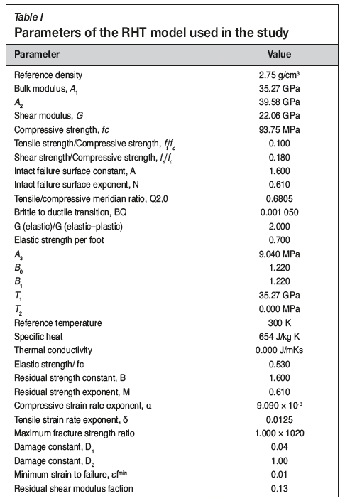
Polynomial EOS (Park and Jeon, 2010) and the Riedel, Hiermaier and Thoma (RHT) strength and failure model are used for Rock II, with the parameters listed in Table I (Riedel et.al., 1999; Riedel, 2000).
For models, the initial condition is set and ideal gas EOS is used for air. The internal energy of air is set as 2.0682.105 J/ kg. For modelling high explosive, ANFO and TNT, Euler solver employing Jones-Wilkins-Lee (JWL) EOS for detonation products is preferred. The JWL Equation [1] is implemented in Autodyn as:
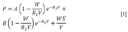
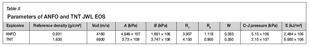
A and B (Pa), the R1and R2coefficients, and W, the Grüneisen coefficient depend on the composition of the explosive. The variable V = v/vois the expansion of the explosive products and E (J/m3) is detonation energy per unit volume. Various authors such as Dobratz and Crawford (1985), Finger et al. (1976), and Souers and Kury (1983) studied the values of JWL coefficients. JWL EOS parameters of ANFO and TNT are as listed in Table II (taken from the library of Autodyn). Euler processor, Compaction EOS, MO Granular strength, Hydro (Pmin) failure are used for sand. The reference density of sand is 2.641 g/cm3.
The mesh size is 10 mm and the same mesh system is applied for both PSM and DCSM. The acceleration due to gravity is set as 9.81 m/s2 through the x direction (according to open pit blasting).
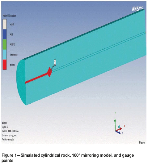
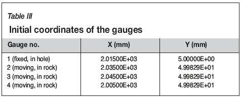
In limestone quarries in Turkey, an average 2.2 m burden and 2.5 m spacing was determined in 89 mm diameter holes and a 10 m bench height by slab blasting tests (Ozkahraman, 1993). Similar geometrical parameters representing the real conditions are chosen for the models. A cylindrical rock specimen is modelled with dimensions of 3000 mm in diameter, 10 000 mm in length, and a 90 mm diameter hole located in the centre (Figure 1). The centre of the drill-hole coordinate at the top of the hole is (0, 0). The length of stemming is 2000 mm in both methods. Gauges are placed in the model as shown in Table III (Figure 1). Gauge 1 is placed 15 mm under the stemming and gauge 2 is 5 mm from the inner surface of hole (50 mm from the hole centre) inside the rock. The main limitation of the gauge is that wherever it is placed, the measurements can be taken only at the middle of the cell.
Initial conditions and boundaries were defined. Interaction and output settings are very important for correct results. The models were built in structured parts that have more than 300 000 nodes and elements. In addition, thousands of cycles were performed.
Detonation was started at the middle of the explosive column (at coordinates 6000, 0). It was assumed in the model that the interface between the plaster stemming and rock was joined, since the plaster plug connects the hole surface. In other words, the plaster plug can move with the main rock mass during blasting (Cevizci, 2013).
Simulation results
The maximum values of pressure, Y-velocity, Y-force, internal energy, acceleration-Y, and compression from the numerical simulation model are given in Table IV. Compression μ is a ratio (Autodyn, 2013), which is
where ρ is density.
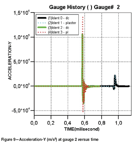
The following nomenclature is used in Figures 2-9:
- Ident 0 - dc : DCSM - limestone - ANFO
- Ident 1 - plaster : PSM - limestone - ANFO
- Ident 2 - dc : DCSM - Rock II - TNT
- Ident 3 - pl : PSM - Rock II - TNT
Measurements at gauge 1 (inside hole)
Figure 2 shows the pressures at gauge 1 location (coordinate 2015, 5) versus time. The maximum pressures using DCSM and PSM are 7 395 and 11 945 MPa for limestone, and 11 876 and 12 962 MPa for Rock II. Figure 3 shows the compression at gauge 1 versus time. Maximum compression with PSM (4.4063) is higher than that for DCSM (0.8327). Similar results were obtained with Rock II. Figure 4 shows the Y component of velocity at gauge I versus time. PSM results in higher maximum velocity in both limestone (519 961 ms-1) and Rock II (473 550 ms-1).
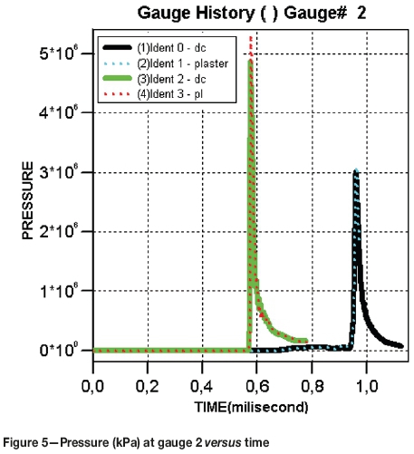
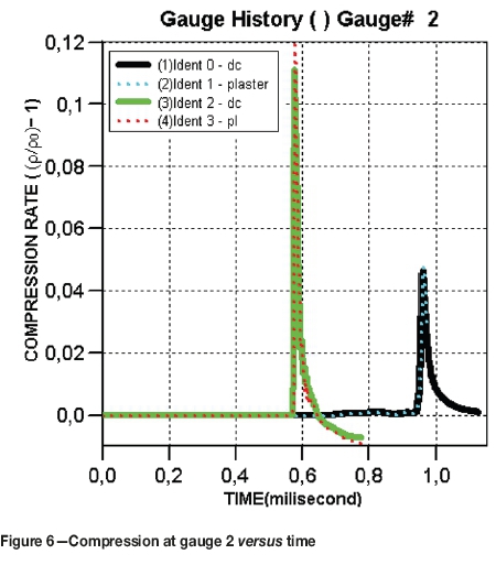
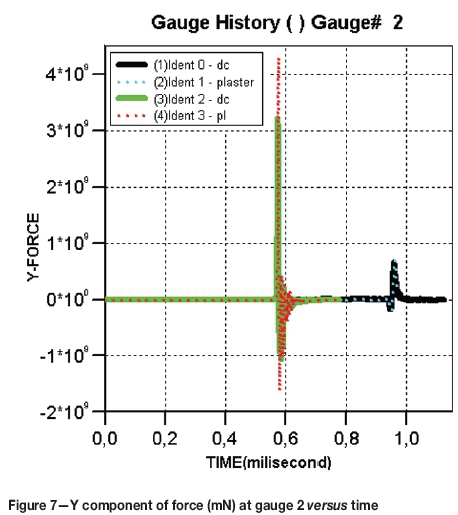
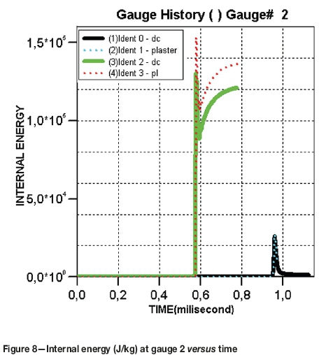
Measurements at gauge 2 (inside rock)
Figure 5 shows pressures at gauge 2 location (coordinate 2035, ~50) versus time. The maximum pressures for DCSM and PSM are 3 015 and 3 104 MPa for limestone, and 4 871 and 5 317 MPa for Rock II. Figure 6 shows values of compression at gauge 2 versus time. The maximum compression for PSM (4 775 χ 10-2) is higher than that for DCSM (4.638 χ10-2). Similar results were obtained with Rock II. Figure 7 shows the Y component of force at gauge 2 versus time. PSM results in a higher maximum Y-force in both limestone (6.466 χ 105, 7.050 χ 105 N) and Rock II (3.213 χ 106, 4.310 χ 106 N). Figure 8 shows internal energy at gauge 2 versus time. Maximum internal energies for DCSM and PSM are 2.585 χ 104 and 2.722 χ 104 J/kg for limestone and 1.299 χ 105 and 1.535 χ 105 J/kg for Rock II. Figure 9 shows acceleration-Y at gauge 2 versus time. Maximum acceleration-Y for PSM (2.392 χ104 m/s-2) is higher than that for DCSM (2.194 χ 104 m/s2). The Rock II results were similar. The results of gauge 3 and gauge 4 are similar to those of gauge 2.
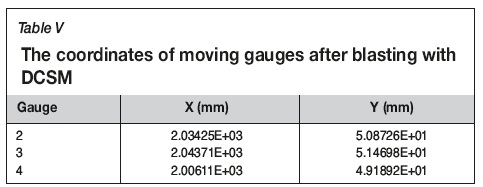
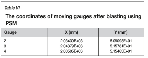
Moving gauges in the rock were preferred, which is available as a default setting in the software. For the ANFO in limestone rounds, the last locations are shown in Table V for DCSM and in Table VI for PSM. With PSM, the gauges are moved further away from the hole towards the free surface by blasting.
Conclusion
Numerical simulations of blasting using conventional DCSM and the newly developed PSM were, for the first time, successively compared by using Autodyn software. The simulations clearly revealed that the blasting performance with PSM was better than that with DCSM, as indicated by most of the measured parameters, in both limestone and Rock II.
Plaster stemming results in high stresses due to the more effective confining of gases inside the blast-holes. In the case of drill cuttings stemming, much of the blast energy is wasted by the gases escaped from the hole. Previous work (Cevizci, 2012 2013, 2014) has shown than the measured PPV values are higher with PSM compared to DCSM. For instance, in one blasting test with the same amount of explosive per delay (Cevizci, 2017), the PPV with PSM was approximately twice that measured using DCSM. The initial shock waves due to the better confinement with moulding plaster are responsible for this increased efficiency of the blast energy used in rock breakage.
Site tests support these numerical simulation results. Blast-induced vibration is increased by using plaster stemming instead of drill cuttings stemming. These indicators show that energy is transferred to the rock more effectively. In situ test results such as better muckpile fragmentation and higher vibration levels with PSM are confirmed by the numerical simulation results. Consequently, because the total drilling and blasting cost with PSM is approximately 20% lower, and the fragmentation is better Cevizci, 2012), PSM should be preferred in blasting operations. Plaster is a cheap material. In situ application of the PSM is slightly difficult, but currently a project is under way on the mechanization of PSM. ANFO is water-resistant and the plaster solution can cause problems. However, using a little drill cuttings in conjunction with plaster can solve this problem.
References
Autodyn. 2013. ANSYS Autodyn User's Manual. Canonsburg, PA. [ Links ]
Benson, D.J. 1992. Computational methods in Lagrangian and Eulerian hydrocodes. Computer Methods in Applied Mechanics and Engineering, vol. 99. pp. 235-394. [ Links ]
Cevizci, H. 2012. A newly developed plaster stemming method for blasting. Journal of the Southern African Institute ofMining and Metallurgy, vol. 112, no. 12. pp. 1071-1078. [ Links ]
Cevizci, H. 2013. A new stemming application for blasting: a case study. Rem: Revista Escola de Minas, vol. 66. pp. 513-519 [ Links ]
Cevizci, H. 2014. Fragmentation, cost and environmental effects of plaster stemming method for blasting at a basalt quarry. Archives ofMining Science, vol. 59. pp. 837-848. [ Links ]
Cevizci, H. 2015. The environmental and ecological effects of plaster stemming method for blasting: A case study. Ekoloji, vol. 24, no. 95. pp. 17-22. doi: 10.5053/ekoloji.2015.11 [ Links ]
Cevizci, H. 2017. The effect of plaster stemming for large hole diameter stripping blasting: A case study. Proceedings of 25th International Mining Congress and Exhibition of Turkey, Antalya. Chamber of Mining Engineers of Turkey. pp. 333-339. [ Links ]
Cevizci, H. and Özkahraman, H.T. 2012. The effect of blast hole stemming length to rockpile fragmentation at limestone quarries. International Journal of Rock Mechanics and Mining Sciences, vol. 53. pp. 32-35. [ Links ]
Dobratz, B.M. and Crawford, P.C. 1985. LLNL explosive handbook: Properties of chemical explosives and explosive simulants. Technical report UCRL- 52997- Chg.2. Lawrence Livermore National Laboratory, California. [ Links ]
Fairlie, G.E. 1998. The numerical simulation of high explosives using Autodyn 2D & 3D. Explo'98: Proceedings of the Institute of Explosive Engineers 4th Biannual Symposium. http://truegrid.com/paper052f.pdf [ Links ]
Finger, M., Lee, E., Helm, F., Hayes, B., Hornig, H., McGuire, R., Kahara, M., and Guidry, M. 1976. The effect of elemental composition on the detonation behavior of explosives. Proceedings of the 6th Symposium on Detonation, San Diego, CA, 24 August 1976. US Department of Energy. [ Links ]
Fiserova, D. 2006. Numerical analyses of buried mine explosions with emphasis on effect of soil properties on loading. PhD thesis, Cranfield University, UK. 239 pp. [ Links ]
Konya, C.J. and Konya, A. 2018. Effect of hole stemming practices on energy efficiency of comminution. Energy Efficiency in the Mineral Industry. Awuah- Offei, K. (ed.). Springer, Cham, Switzerland [ Links ]
Oran, E.S. and Boris, J.P. 2001. Numerical Simulation of Reactive Flow. 2nd edn. Cambridge University Press. 529 pp. [ Links ]
Özkahraman, H.T. 1993. Critical evaluation of blast design parameters for discontinuous rocks by slab blasting. PhD thesis, Middle East Technical University, Ankara. [ Links ]
Park, D. and Jeon, S. 2010. Reduction of blast-induced vibration in the direction of tunneling using an air-deck at the bottom of a blasthole. International Journal of Rock Mechanics and Mining Sciences, vol. 47. pp. 752-761. [ Links ]
Riedel, W., Thoma, K., Hiermaier, S., and Schmolinske, E. 1999. Penetration of reinforced concrete by BETA-B-500, numerical analysis using a new macroscopic concrete model for hydrocodes. Proceedings of the Ninth International Symposium on Interaction of the Effects of Munitions with Structures. Berlin, 3-7 May 1999. Akademie der Bundeswehr für Information und Kommunikation. pp. 315-22. [ Links ]
Riedel, W. 2000. Beton unter dynamischen lasten meso-und makromechanische modelle und ihre parameter. Ernst-Mach-Institut, Freiburg. [ Links ]
Snelling, W. and Hall, C. 1912. The effects of stemming on the efficiency of explosives. US Department of the Interior, Bureau of Mines, Washington, DC. [ Links ]
Souers, P.C. and Kury, J.W. 1993. Comparison of cylinder data and code calculations for homogeneous explosives. Propellants, Explosives, Pyrotechnics, vol. 18. pp. 175-183. [ Links ]
Toro, E.F. 1997. Riemann Solvers and Numerical Methods for fluid dynamics: A Practical Introduction. Springer-Verlag. Berlin. 592 pp. [ Links ]
Zukas, J.A.2004. Introduction to Hydrocodes. Studies in Applied Mechanics. Elsevier. pp. 175-183. [ Links ] ♦
 Correspondence:
H. Cevizci
Email: halimcevizci@sdu.edu.tr
Received: 29 Mar. 2018
Revised: 29 Sep. 2018
Accepted: 29 Oct. 2018
Published: April 2018
ORCiD ID: H. Cevizci https://orchid.org/0000-0003-4016-5136

