


Services on Demand
Article
 English (pdf)
 Article in xml format
 Article references
Indicators

Related links
-
 Cited by Google
 -
 Similars in Google
Share

 Permalink
Journal of the Southern African Institute of Mining and Metallurgy
On-line version ISSN 2411-9717
Print version ISSN 2225-6253
J. S. Afr. Inst. Min. Metall. vol.119 n.5 Johannesburg May. 2019
http://dx.doi.org/10.17159/2411-9717/16/287/2019
PAPERS OF GENERAL INTEREST
Field validation of estimated primary fragment size distributions in a block cave mine
S. Annavarapu
Master Geotech Services Pvt LTD, Nagpur, India
SYNOPSIS
Fragment size distributions play an important part in the design and planning of block cave mining operations. Though several methods have been proposed for estimating fragment size distributions in advance of mining, the calibration of these estimating procedures to field measurements has been a challenge. The Block Size Estimator (BSE) program was developed for providing an assessment of primary fragmentation expected in a block cave mine using drill-core piece length data and joint characteristics from the exploration and geotechnical evaluation programmes. In order to validate the results from the BSE program, the drill-core piece length data and the joint characteristics in different rock types from the DOZ block cave mine in Indonesia were used to help generate fragment size distributions in different areas of the mine. The predicted fragment size distributions were compared with the fragmentation observed at the drawpoints during operation of the mine.
This paper presents the details of the validation of the fragment size estimates by the BSE program using fragment size distribution data from the drawpoints at the extraction level at the DOZ block cave mine, and the challenges encountered in developing reasonable correlations between the estimated and measured fragment size distributions.
Keywords: block caving, fragmentation, size distribution, rock mass characteristics, modelling.
Introduction
The assessment of fragmentation is an important aspect of the design and planning of the block cave mining method, and forms an integral part of the design of the excavations at the extraction level and the selection of material handling systems for transporting the ore to the processing stations. Secondary blasting requirements can also be estimated based on the fragment size distributions developed for the block cave (Laubscher, 1994).
Several methods of estimating fragment size distributions in block cave mines have been developed based on joint set parameters estimated from structural data from oriented core drilling campaigns and mapping of available excavations and outcrops. The BCF program (Esterhuizen, 1999) estimates the fragmentation using a combination of empirical, analytical, and rational methods to model the behaviour of materials during the primary and secondary fragmentation processes. The program JKFrag uses advanced tessellation of joint traces to create rock blocks and then generate fragment size distributions (Brown, 2002). Nickson, Coulson and Hussey (2000) presented the details of processing of the geotechnical data from the Mont Porphyre project, including an assessment of block sizes from the data collected on the core logging sheet. The distance between natural fractures was used to create distributions of block lengths, and a distribution of potential block sizes was estimated assuming that the blocks had equal dimensions in all directions. The results agreed closely with the results of the BCF program. Hadjigeorgiou, Grennon, and Nickson (2002) demonstrated the use of oriented borehole data to provide characteristic block size distributions for a mining project using a software package called Stereoblock, which generates a three-dimensional joint network for a given volume and calculates the volumes of blocks created by the intersections of these joints, simulated as circular planes. The distributions of joint orientation and joint spacing generated from statistical analysis of the oriented core data are used for the creation of the Stereoblock model. The diameter of the circular planes representing the joints is determined based on the mean and standard deviation of the joint trace length obtained from scan-line mapping.
Of these approaches, the BCF program has found the greatest acceptance in the block cave sector and has been used extensively for developing fragment size distributions from the scoping study stage (with limited geotechnical data) to the operational stage (with available observations for back-analyses).
However, Butcher and Thin (2007) reported that the model ore blocks are generated independently of the jointing statistics.' The fragmentation results from the BCF program are often too coarse because the effects of block formation due to stress-induced joint extension, and stress-induced failure of rock bridges between joints are not considered.
The availability of structural data from different parts of a block cave mine is often limited by the extent of the geotechnical programme in general and the core orientation programme in particular. The cost and time associated with these programmes, especially in the early stages of exploration of the orebody, makes it difficult to assign significant resources to them. However, the larger number of exploration holes from which core piece length data is available makes a case for developing an algorithm for using this data for estimating fragment size distributions within the block cave. With this motivation, the Block Size Estimator (BSE) program was developed for estimating the block size distribution using core piece length to generate in-situ and primary fragmentation estimates for block cave operations (Srikant, 2013).
Validating the fragment size estimates produced by the various available programs through calibration against field observations is essential for the development of confidence in the prediction of fragment size distributions. Although drawpoint fragmentation estimation using photographic methods, comparative charts, and size assessment has been undertaken at many mines (Srikant, 2004; Brown, 2007) a major problem in such validation studies is that the programs develop estimates of in-situ or primary fragmentation and use empirical approaches or expert systems for estimating the secondary fragmentation at different heights of draw. The validation is therefore for the complete system of in-situ block size estimation followed by the simulation of the process of comminution within the draw column (Moss, 2012).
Recent studies at Ridgeway Deeps and Cadia East mines in Australia (Brunton, Lett, and Thornhill, 2017) compared the fragment size distribution predicted using the BCF software with the observed fragment size distribution generated by analysis of photographs of the drawpoints using the SPLIT Desktop system. The authors concluded that BCF predictions matched relatively well to the measured coarser component of the fragmentation distribution (top size and P80), but for the finer component of the fragmentation distribution (P50 and P20), the BCF predictions were significantly coarser than the measured values.
Since the only observations that can be used to calibrate the primary fragmentation estimates are at the drawpoints at the extraction level of the block caves, it is difficult to correlate the primary fragment size distributions estimated by the program with field observations. The fragments observed at the drawpoints can be expected to be finer than the primary fragments since they would have been subjected to comminution forces within the draw column. However, limited breakdown of the rock fragments is expected within the first 50 m of draw from the drawpoints and the fragment size distributions may be closer to the primary fragmentation.
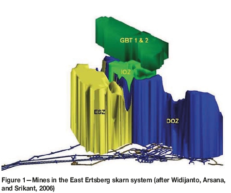
The observations of fragmentation at the drawpoints in a block cave mine in Indonesia during the period from 2004 to 2007 were used to validate the outputs from the BSE program. The mines of the Ertsberg District, in the province of West Papua in Indonesia, are operated by PT Freeport Indonesia (PTFI). The Deep Ore Zone (DOZ) mine is a copper-gold deposit found on the northeast flank of the Ertsberg diorite and lies within the Ertsberg District of Papua Indonesia. The DOZ mine is essentially the third lift of the block cave operations that have exploited the East Ertsberg skarn system (Figure 1), and benefits from experience gained while mining the previous block caves in the same skarn system. The mine is laid out for LHD mining using 6.1 m3 and 8.4 m3 capacity LHDs at the extraction level, from where the broken rock is transferred through grizzlies feeding 55 t low-profile dump trucks which direct-dump into a gyratory crusher with a 1.37-m wide feed opening size (Barber, Thomas, and Casten, 2000).
Four major rock types are mined in the DOZ - Ertsberg diorite, forsterite skarn, magnetite skarn, and DOZ breccia. Fragmentation characteristics for these rock types vary from fine (in the DOZ breccia) to coarse (in the diorite). The fragment size distributions for the DOZ block cave were estimated by the BSE program using the drill-core piece length data from different zones in the DOZ block cave and the joint set characteristics of the different rock types. The estimated fragment size distributions show significant correlation to the observed fragmentation at the drawpoints in similar rock conditions for the first 50 me of draw.
Estimating fragment size distributions
The BSE program requires the drill-core piece lengths, core piece orientation, and the joint set characteristics (joint set dip, dip direction, and spacing) to generate the fragment size distributions. At the DOZ mine, several campaigns of geotechnical drilling resulted in the development of a large data-set with good core piece length data. Drill-hole survey data was also available for many of the drill-holes, which could be used to generate the orientation of each ore piece. Joint set characteristics were available for different rock types from campaigns of geological and geotechnical mapping of underground excavations in different rock types.
Drill-core piece length data
During several campaigns of drilling at the DOZ mine, geotechnical and geological data was collected and stored in a comprehensive database. The collected data included information that could be used to develop drill-core piece length data. From each drill run, the data collected included the length of the drill run (Len_run), the core diameter (Dia), the cumulative length of recovered core (Len_Rec), the cumulative length of whole core pieces longer than twice the core diameter (Len_RQD), the cumulative length of broken core (Len_br), the length of the longest piece of whole (non-broken) core (Len_lp), the number of whole core pieces (Num_pc), the cumulative length of pieces that are longer than or equal to 0.4 m length (Len_0.4), the cumulative length of pieces that are longer than or equal to 0.2 m length (Len_0.2), and the cumulative length of pieces that are 1.0 cm in size (Len_0.01). Drill-hole geotechnical data for the DOZ mine was sorted into a series of size ranges and the cumulative lengths of logged core pieces with lengths that fall within each bin size were tallied.
For each drill run within the data-set, the downhole survey data was used to calculate the azimuth and plunge of the drill run and this information was assigned to each core piece within the drill run. The enhanced data-set now contained drill-core piece lengths and orientation data for each core piece. The drillhole data was then sorted by location and rock type so that the predicted fragmentation could be compared with that observed at the drawpoints. The footprint of the DOZ block cave was split into three-panel wide sections, and all the drill-hole intercepts within each section lying within the expected column height for the panels in the section were accumulated and sorted by rock type. The resulting data-set for each rock type and panel within the first 50 m of the block cave was then used for developing the primary fragment size distributions for each of the sections.
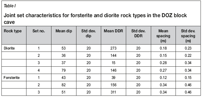
Joint set characteristics for different rock types
The joint set characteristics used in the BSE model for the diorite and forsterite skarn rock types were generated from analysis of oriented core drilling and from mapping in the available drifts at the extraction and undercut levels in the DOZ block cave (Table I).
The Block Size Estimator program
The development of the primary fragment size distribution for block cave mining from drill core data requires the estimation of three-dimensional volumetric fragment sizes from one-dimensional drill-core piece lengths. The basic premise of the BSE program is that each core piece represents an in-situ block intersected by the drill-hole. The block is created using three almost orthogonal joint sets. Adjacent joints within the same joint set are expected to have similar orientations and rock blocks can, therefore, be expected to be parallelepipeds in shape. The volume of the parallelepiped is estimated based on the length of the drill-core piece and the orientation of the drill-hole with respect to the sides of the parallelepiped.
The conversion of the one-dimensional drill-hole data into a three-dimensional block volume is undertaken based on trigonometry concepts using the core piece length (l), drillhole azimuth (Θ) and drill-hole plunge (φ) along with the dip direction (DDR), dip (DIP), and spacing (s) of joint set data. The BSE computer program was developed based on the concepts presented in Srikant and Nicholas (2004), as shown in Figure 2.
Primary fragmentation estimates in the DOZ
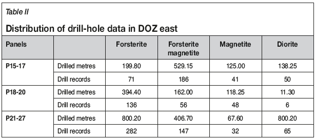
The primary fragment size distributions were estimated for the DOZ mine based on the geotechnical drilling data available from the different sectors of the DOZ. However, most of the drawpoint fragmentation observations during the period of data collection were from the east side of the block cave (panels 13-27), so only the relevant data was analysed. Table II shows the number of drill-core data records available in each zone by rock type. Since some of the zones within the footprint of the DOZ block cave had sparse data within the lower 50 m of the draw column, the data from these zones was not used to estimate fragment size distributions in that zone. In order to avoid poorly distributed data, zones with less than 30 drill-core records were not analysed for fragment size distribution.
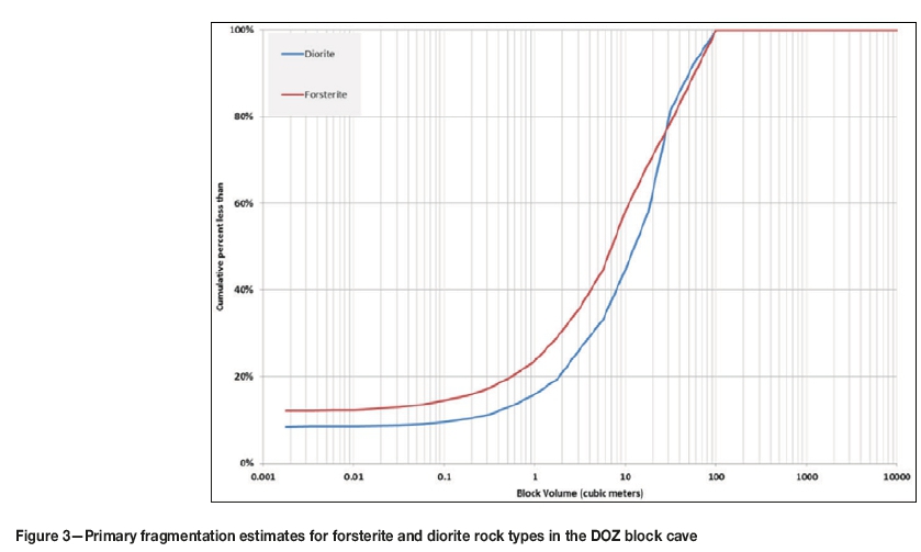
The overall primary fragmentation estimates generated by the BSE model for the DOZ mine for the forsterite skarn and the diorite rock types are shown in Figure 3.
Problems with estimating fines
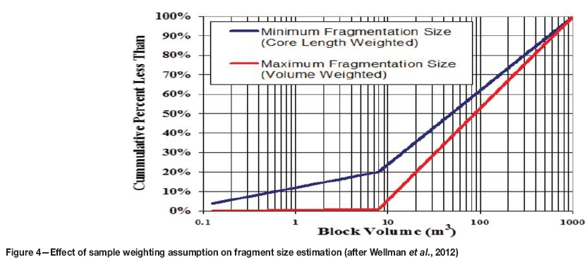
The estimation of fragment sizes from drill-hole data requires the conversion of one-dimensional piece length data to three-dimensional block size information. In the BSE program, each core piece from the drill-hole was assumed to represent a rock fragment and average aspect ratios were used to generate a volume-weighted block size distribution. Wellman et al. (2012) studied the impact of this assumption on the distribution of block sizes and concluded that the use of the volume-weighted or length-weighted, or some intermediate weighting factor to represent the distribution of block sizes, is key in representing the distribution of expected block sizes, as shown in Figure 4.
The development of an appropriate model for estimating fragment size distributions within a region using drill-hole data is essentially a sampling problem. One- and two-dimensional data-sets are used to estimate the appropriate three-dimensional size distribution. Although the BSE model can help convert even small core pieces to small block volumes, the percentage of fines generated by the smallest pieces was observed to be very small. The smallest core piece length used in the computation of rock fragment volumes was 0.005 m (5 mm), which can be converted to a block volume of 0.0000125 m3 (125 mm3), which is still significantly larger than the fines observed at the drawpoints. In order to better represent fines in the primary fragmentation estimates from the BSE model, the percentage of fines is estimated to be equal to the percentage of the drill-hole that can be correlated to fines (Len_br + Len_run - Len_rec). This formulation was included in the BSE model to help generate fines in the primary fragmentation estimates.
Drawpoint mapping
Measuring fragmentation at the drawpoints of a block cave mine is a very difficult task and current methods of mapping yield estimates of the actual fragmentation. Field measurements have been conducted at the Tongkuangyu copper mine (Aimin and Yongxue, 2000), but such techniques are not practical in a high-production mines with large equipment and low manpower. Mapping of the fragmentation at the drawpoints at the DOZ block cave was undertaken in several campaigns to help correlate the predicted and observed fragmentation (Srikant, Nicholas, and Rachmad, 2004). Drawpoint fragmentation data from the DOZ mine was also collected by students from the Institut Teknologi, Bandung (ITB) in Indonesia (Lukito, 2005; Sinaga, 2005). Recognizing that observers can more readily assess block side lengths rather than block volumes in a drawpoint, the procedure relied on estimates of block side lengths as illustrated in Table III, which shows a partially completed drawpoint fragmentation log.
The material size distribution is divided into five categories: fines, small block, intermediate block, large block, and oversize. The first three categories represent the material size that could pass through a 1 χ 1 m grizzly. The large blocks category represents the material that could be handled by the LHDs without any size reduction. The oversize category represents the material that requires either secondary blasting at the drawpoint or hang-up blasting. The dimensions of the largest block were also recorded to help assess average aspect ratios for the different rock types.
The observer counts the number of intermediate blocks (0.5 m to 1 m side length) and large blocks (1 m to 2 m side length) and multiplies the numbers with proportional area-based percentages, 2% for each intermediate block and 5% for each large block. The percentages of oversize and fines were estimated, while the small blocks category was calculated to make up the rest. The draw height information for each drawpoint, which was important for the analysis, was collected through the Cave Management System (CMS), a monthly-planning interface between the long-term block cave planning software and the daily production planning systems at the DOZ block cave (Samosir, Brannon, and Diering, 2004). Rock type information was collected through routine geological mapping at the drawpoints. Several rock types are normally observed at each drawpoint, and the percentage of occurrence of the different rock types was recorded. For the purposes of this study, the most dominant rock type was assigned to the drawpoint.
In many cases, fines were observed to cover several small and medium boulders at the drawpoint and thus the percentage of fines recorded during drawpoint fragmentation mapping was found to be high (Srikant, 2006). This is particularly true in the first 10 m of draw, where there is a high possibility of the large primary fragments being covered by the fine material resulting from the undercut and/or drawbell blasts.
The drawpoint mapping method described above was easy to implement in the DOZ mine, but cannot be used as an accurate measure of fragment size distributions at the drawpoints. The measurements are known to be quite subjective, but a large data-set was available for calibration of fragment size distributions estimated using the BSE program. While several attempts were made to measure drawpoint fragmentation using analysis of photographs taken at the drawpoints in the DOZ mine, the procedures required environments relatively free of dust and moisture and were difficult to establish as a routine. The measurements by Lukito and Sinaga are of value since they were conducted by the same persons over several weeks.
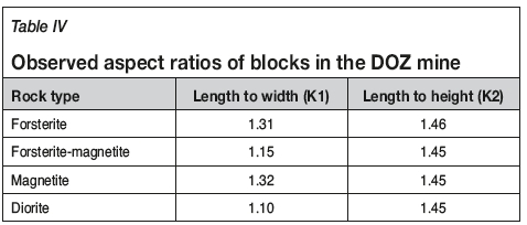
Visual estimates of drawpoint fragmentation can potentially be used to calibrate the results of fragmentation analyses. However, correlation of the estimates with observations proved to be a challenge since the fragmentation estimates were reported as volumetric estimates by convention, and the drawpoint mapping procedures developed for the DOZ evaluated the fragmentation observed at the drawpoints as linear measures. Table IV shows the average aspect ratios observed at the drawpoints for the different rock types in the DOZ mine. These observed aspect ratios for the two rock types were used for converting the linear fragment size estimates from drawpoint mapping to volumetric estimates.
Comparison of observed and predicted primary fragmentation
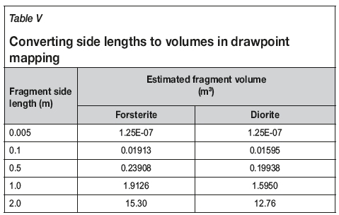
Primary fragment size distributions were developed from the block volumes generated by the BSE models using drill-hole core piece lengths from the lower 50 m in the draw column at the DOZ mine. The distributions from each zone were compared to the fragment size distributions observed at the drawpoints in the same zone with draw heights up to 50 m. The linear dimensions in the drawpoint fragmentation mapping form were converted to volumes using the values in Table V, which are based on the aspect ratios of the blocks in the forsterite and the diorite. Drawpoints in the DOZ mine are 4.5 m wide and 4.5 m high and the total volume of rock in the drawpoint was estimated to be 65 m3 using an angle of repose of 35 degrees. The dimensions of the largest block observed in the drawpoint were used to estimate the volume of the largest block. The fragment size distribution was adjusted accordingly to account for the volume of the largest block observed in the drawpoint.
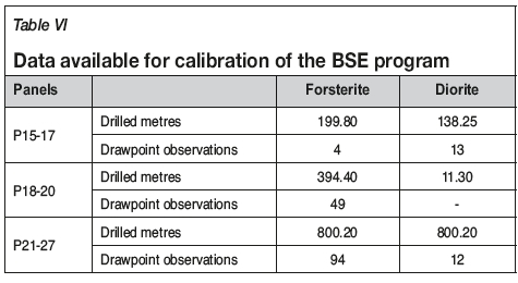
More than 3800 observations of fragment size distributions at the drawpoints in the DOZ were reported by Srikant (2006) and Sinaga (2005). The observations were sorted by rock type, panel, and draw height. Though 8091 m of drill-core data records are available from the lower 50 m of the DOZ mine along with 580 drawpoint fragmentation records, only eight zones could be used for calibrating the BSE model against primary fragmentation observations. These zones are shown in Table VI.
Forsterite skarn
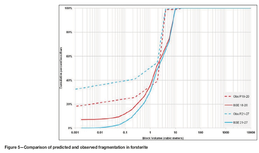
A total of 143 drawpoint observations were recorded in the forsterite rock type for draw heights less than 50 m. Of these, 49 observations were from drawpoints in panels 18-20 and 94 were from drawpoints in panels 21-27. The predicted and observed primary fragment size distributions for these panel groups within the forsterite rock type are shown in Figure 5 and show a reasonable correlation, though the predicted fragmentation is slightly coarser than the observed fragment size distribution. A significant reason for this difference could be the fact that large boulders are often obscured by fines.
Diorite
A total of 28 drawpoint observations were recorded in the diorite rock type for draw heights less than 50 m. Of these, three observations were from drawpoints in panels 12-14, 13 were from drawpoints in panels 15-17, and 12 observations were from drawpoints in panels 21-27. The predicted and observed fragment size distributions for these panel groups within the diorite rock type are shown in Figure 9. Unlike in the forsterite rock type, there is a significant difference between the observed and predicted fragment size distributions with the predicted fragment size distribution being coarser by an order of magnitude. An examination of the fragment sizes generated by the BSE model shows that there are two blocks with volumes greater than 100 m3. These blocks have resulted from core piece lengths greater than 3 m and the higher aspect ratios in the diorite rock type.
Conclusions
The BSE program was developed to estimate primary fragment size distributions using drill-core data, especially for block cave operations. The program uses drill-core data, which is generally available from most parts of the areas to be mined, from the initial stages of discovery of the deposit to mine development, along with joint set information so that the estimates can reflect the variability of fragmentation within the orebody. The BSE program helps the mine engineering group to evaluate fragmentation and plan mine facilities prior to construction of the mine.
Success in the estimation of primary fragmentation at the extraction level in a block cave is limited by the large number of unknowns about the rock mass and about the processes of comminution within the draw column. The characteristics of the jointed rock mass can only be estimated based on data generated from geotechnical drilling, and the spatial relationships of these characteristics are less understood than those of mineral compositions and assay values. The density of geotechnical data is also often very low and there is, therefore, less confidence in the extrapolation of the data to areas where there has been no drilling or even in the interpolation of data between adjacent drill-holes.
Drawpoint fragmentation mapping information can be a very useful tool in the calibration of procedures for estimating fragmentation. However, such mapping was found to be time-consuming and required a geological or geotechnical technician to interrupt operations while taking measurements of fragmentation at the drawpoints. The analysis of scaled photographs of fragmentation at the drawpoints can help reduce the time taken to obtain the information from the field and also reduce the subjectivity involved in mapping fragmentation at the drawpoints, but the lighting conditions at the drawpoints and the presence of dust and moisture in the underground environment made it difficult to take quality photographs that can be analysed using programs such as SPLIT Desktop to develop fragment size distributions. While Zamora (2006) developed a system to quickly take scaled photographs at the drawpoints in El Teniente, reducing the interruption of mucking operations at the extraction level, the use of the camera system to take scaled photographs at the drawpoint in the DOZ was not successful due to the moisture and dust levels at the drawpoints.
A campaign of drawpoint fragmentation assessment using photographs from the drawpoints was initiated in 2006 and the data was analyzed by Lukito (2005) using the SPLIT Desktop software. Though the data was collected over a period of 3 months, adequate correlations could not be drawn between the cave height and the fragment size distributions. Most of the problems were related to the covering of boulders with fines, which caused an under-estimation of the larger blocks at the drawpoint.
In this study, the BSE model was calibrated against the limited number of drawpoint fragmentation mapping observations from the DOZ block cave collected during the period 2004 to 2007. The use of a larger database of fragment size distributions from different mines in different rock types is recommended to help improve calibration of the BSE model. In addition, efforts must be undertaken to better understand the processes of comminution within the draw column.
Acknowledgements
This paper is based on the study conducted by the author as part of his PhD dissertation and was undertaken at the DOZ mine with the approval of the management of PT Freeport Indonesia. The author gratefully acknowledges the assistance and guidance of David Nicholas of Call & Nicholas, Inc., David Flint, George MacDonald, and Tim Casten and Chuck Brannon of Freeport McMoRan during the course of this study. The guidance of Mary Poulton, John Kemeny, and Sean Dessureault at the University of Arizona is also acknowledged.
References
Aimin, Z. and Yongxue, S. 2000. Application of block caving system in the Tongkuangyu Copper Mine. Proceedings of MassMin 2000. Chitombo, G. (ed). Australasian Institute of Mining and Metallurgy, Melbourne, Australia. pp. 325-331. [ Links ]
Barber, J., Thomas L., and Casten, T. 2000. Freeport Indonesia's Deep Ore Zone Mine. Proceedings of MassMin 2000. Chitombo, G. (ed). Australasian Institute of Mining and Metallurgy, Melbourne, Australia. pp. 289-294. [ Links ]
Brown, E.T. 2007. Block Cave Geomechanics. 2nd edn.. JKMRC, University of Quensland, Australia. [ Links ]
Brunton, I., Lett, J., and Thornhill, T. 2016. Fragmentation prediction and assessment at the Ridgeway Deeps and Cadia East block cave operations. Proceedings of the Seventh International Conference and Exhibition on Mass Mining (MassMin 2016). Australasian Institute of Mining and Metallurgy, Melbourne. pp 151-159. [ Links ]
Butcher, R.J. and Thin, I.G.T. 2007. The inputs and choices for predicting fragmentation in block cave projects. Proceedings of the 1st International Symposium on Block and Sub-level Caving, Cape Town. Southern African Institute of Mining and Metallurgy, Johanesburg, South Africa. pp. 35-49. [ Links ]
Esterhuizen, G.S. 1999, BCF Version 3.0 - A program to predict block cave fragmentation - Technical reference and user's guide. Society for Mining, Metallurgy & Exploration, Littleton, Colorado. [ Links ]
Hadjigeorgiou, J., Grennon, M., and Nickson, S. 2002. In situ block size distributions from borehole data: a case study. Transactions of the Society for Mining, Metallurgy and Exploration, vol. 312. pp. 20-27. [ Links ]
Laubscher, D.H. 1994. Cave mining - the state of the art. Journal of the South African Institute of Mining and Metallurgy, vol. 94, no. 10. pp. 279-292. [ Links ]
Lukito, H.A. 2005. Analysis of secondary fragmentation size distribution in DOZ block cave mine, PT Freeport Indonesia. B. Mining Report. Institut Teknologi Bandung, Bandung, Indonesia. [ Links ]
Moss, A. 2012. Caving: The need to measure. Proceedings of the 2nd Mining Innovation Conference, Sydney, Australia. Australasian Institute of Mining and Metallurgy, Melbourne. pp. 3-4. [ Links ]
Nickson, S., Coulson, Α., and Hussey, J. 2000. Noranda's approach to evaluating a competent deposit for caving. Proceesings of MassMin 2000, Brisbane. Australasian Institute of Mining and Metallurgy, Melbourne. pp. 367-383. [ Links ]
Samosir, E., Brannon, C., and Diering, T. 2004. Implementation of cave management system (CMS) tools at the Freeport DOZ Mine. Proceedings of MassMin 2004. Karzulovic, A. and Alfaro, M.A. (eds). Instituto de Ingenieros de Chile, Santiago, Chile. pp. 513-518. [ Links ]
Sinaga, H.N. 2005. Analyze efficiency explosive and secondary blasting cost based on HOD and rock type dominant. B. Mining Report. Insitut Teknologi Bandung, Bandung, Indonesia. [ Links ]
Srikant, Α., and Nicholas, D.E. 2004. Assessment of primary fragmentation from drill core data. Proceedings of MassMin 2004. Karzulovic, A. and Alfaro, M.A. (eds). Instituto de Ingenieros de Chile, Santiago, Chile. pp. 55-58. [ Links ]
Srikant, Α., Nicholas, D.E., and Rachmad, L. 2004. Visual estimation of fragment size distributions in the DOZ block cave. Proceedings of MassMin 2004. Karzulovic, A. and Alfaro, M.A. (eds). Instituto de Ingenieros de Chile, Santiago, Chile. pp. 286-290. [ Links ]
Srikant, Α. 2006. Fragment size estimation and measurement in the DOZ block cave. Mining Engineering, vol. 58, no. 10. pp. 43-47. [ Links ]
Srikant, Α. 2013. Estimating primary fragment size distributions from drill core data. PhD dissertation, University of Arizona, Tucson, AZ. [ Links ]
Widijanto, E., Arsana, N., and Srikant, Α. 2006. Geotechnical challenges in the DOZ block cave mine. Rock Mechanics in Underground Construction: Proceedings of the 4th Asian Rock Mechanics Symposium.. Leung, C.F. and Zhou, Y.X. (eds). World Scientific, Singapore. p. 210. [ Links ]
Wellman, E.C., Annavarapu, S., Pratt, R.W., and Nicholas, D.E. 2012. Prediction of fragmentation - an update of the Core2Frag program. Proceedings of MassMin 2012. Sudbury, Ontario. Canadian Institute of Mining, Metallurgy and Petroleum, Montreal. [ Links ]
Zamora, Α. V. 2006. Persoanl communication. [ Links ] ♦
 Correspondence:
S. Annavarapu
Email: mgsrikant@gmail.com
Received: 16 July 2016
Revised: 10 June 2018
Accepted: 29 Oct. 2018
Published: May 2019
ORCiD ID: S. Annavarapu https://orchid.org/0000-0001-6054-4104

