


Serviços Personalizados
Artigo
 Inglês (pdf)
 Artigo em XML
 Referências do artigo
Indicadores

Links relacionados
-
 Citado por Google
 -
 Similares em Google
Compartilhar

 Permalink
Journal of the Southern African Institute of Mining and Metallurgy
versão On-line ISSN 2411-9717
versão impressa ISSN 2225-6253
J. S. Afr. Inst. Min. Metall. vol.119 no.4 Johannesburg Abr. 2019
http://dx.doi.org/10.17159/2411-9717/17/390/2019
PAPERS OF GENERAL INTEREST
Geotechnical data analysis to select a feasible method for development of a long axis, large diameter vertical ventilation shaft
E.J. WallsI, II; W.C. JoughinI; H-D. PaetzoldIII
ISRK Consulting (Pty) Ltd, South Africa
IIJeWal Geotechnical (Pty) Ltd, South Africa
IIIPalabora Mining Company (Pty) Ltd, South Africa
SYNOPSIS
In selecting a suitable method to sink a vertical shaft for underground access, a number of constraints influence the ultimate decision of where and how to develop the shaft, not least among these being safety, development and construction time, and cost. Two additional considerations stand out: these being geotechnical conditions and technology, the latter taking into account existing underground access. Assuming a project for which an existing underground excavation is available, it is tempting to build a shaft sinking project from the outset based on the raiseboring method, which has the potential to be the safest, fastest, and least expensive method provided that geotechnical conditions permit.
And therein lies the rub: regardless of project time or cost constraints, when it comes to raiseboring a long (say, greater than 500 m), large diameter (greater than 4.5 m) shaft, the rock mass conditions ultimately dictate what method of shaft sinking will be feasible. Over the course of several studies for a particular project, several geotechnical analyses were carried out specifically for the purpose of developing a shaft by raiseboring. Risk analysis and experience showed that where the rock mass conditions indicated an unacceptably high risk potential, an alternative method needed to be considered, even if this meant increasing both the time and financial requirements.
In this paper we present an overview of geotechnical investigation practices for shaft sinking. Decision-making thresholds for raiseboring or other methods of shaft sinking are discussed, including probabilities of failure, empirical rock mass classification, basic wedge failure, and back-analysis of a failed case. The design of appropriate support, and analysis of relative safety benefits for various shaft sinking methods, falls outside the scope of this work, and will be presented in a separate paper.
Keywords: raiseboring, probability of failure, rock mass classification.
Introduction
The potential for rock mass failure during shaft development and construction affects whether a project is completed safely, on time and on budget. During the course of several studies to establish ventilation shafts for an underground expansion project, geotechnical analyses of rock mass stability and failure potential were carried out. The investigations were guided by the method of McCracken and Stacey (1989) together with insights from Peck and associates (Peck, 2000; Peck and Lee, 2007, 2008; Peck, Coombes, and Lee, 2011).
Considerations for method selection
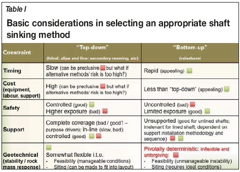
Regardless of project constraints involving time, budget, and safety, an understanding of the geotechnical conditions together with technology limitations is critical for determining which method of shaft sinking will work. Where an existing underground excavation permits, raiseboring is attractive by way of being rapid and cost-effective, with limited exposure of workers within the shaft during excavation and therefore a relatively low safety risk compared with conventional, labour-intensive methods such as blind sinking, slipe and line, or other downward-orientated excavation methods, not to mention Alimak shafts, V-Mole, among others (Table I).
However, for a long (> 500 m), large diameter (> 4.5 m) raisebored shaft, the probability of encountering unfavourable (high-risk) rock conditions is greater than for a short shaft. This factor, in the authors' opinion, is currently inadequately addressed in shaft planning projects. Additionally, an increased diameter presents an increased surface area for wedges to form and stress-driven spalling to occur. The shaft walls must be able to stand up (be stable) for the period that it takes to complete the reaming. For example, a 1000 m or longer shaft that is advanced, say, 3 m to 5 m per day must be stable for up to six months to one year before staged support can be installed. Only once the shaft has been completed can support be installed, assuming that the shaft will be equipped with a headgear in order to do so (not typically needed for an unequipped ventilation shaft, as for this project).
Rock mass failure prior to completion of a raisebored shaft can have catastrophic consequence for the project. The project will incur increased costs, be delayed, the site may need to be abandoned entirely if it cannot be rehabilitated, and equipment may need to be sacrificed if not retrievable. Major wedge failure from the advancing face can occur, impacting the performance of the reamer. Alternately, uncontrolled unravelling of the sidewalls presents a risk to safety and equipment while attempting to retrieve the cutter head during cutter changes, as well as a risk to the long-term stability and functionality of the shaft.
Currently, technologies for raiseboring shafts longer than 500 m preclude the concurrent installation of support of any kind, be it shotcrete, tendons, mesh, or otherwise. This is due to the length of the shaft, which inhibits remote shotcrete efforts, the presence of an advancing face that makes conditions unsafe for personnel to access and install support, while if support is indeed installed, the reamer diameter must then be reduced in order to re-enter and complete the shaft.
It is therefore important to regard the potential risk of rock mass failure as a major deciding factor when choosing the best shaft-sinking method for a project. Geotechnical conditions must be favourable over an extended linear distance (> 1000 m in this case) and be within a tolerable threshold for failure risk.
Geotechnical risk analysis
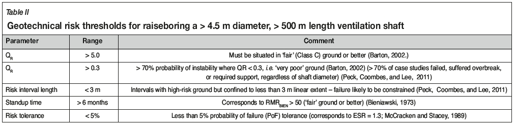
An account of geotechnical risk analysis criteria was put forward by McCracken and Stacey (1989) followed by insights of Peck and associates (Peck; 2000; Peck and Lee, 2007, 2008; Peck, Coombes, and Lee, 2011). A summary of geotechnical risk considerations for the development of a large diameter (> 4.5 m), long (> 500 m), unlined and unsupported ventilation shaft is presented in Table II. Other risk parameters not included in the table are less influential. These include, among others:
> RQD/Jn: an indication of block failure potential in relation to shaft diameter where RQD represents rock quality designation and Jn represents the number of joint sets (Barton, 2002; Peck et al; McCracken and Stacey, 1989)
> Jr/Ja: an indication of shear failure potential, found to be somewhat inconclusive as an indicator for stability in relation to shaft diameter
> Work by Andersen (2015) includes a stability index (SSL) based on a combination of Jr and Ja (Barton, 2002); however, this work was not available at the time of the project and would be worthwhile to incorporate in shaft projects going forward.
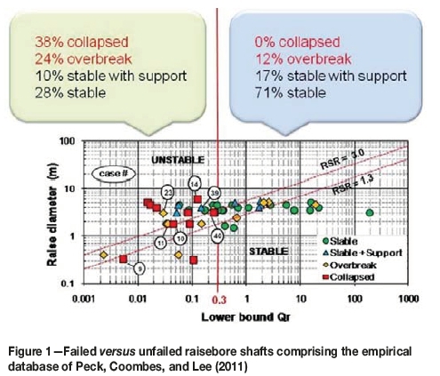
It is worthwhile to note that the approaches of McCracken and Stacey (1989), and Peck, Coombes, and Lee e2011) are largely empirical and as such carry certain limitations (Figure 1. One such obvious limitation is the predominance of data from shafts with a diameter less than or equal to 4.5 m, and only a single case for 6.0 m, which failed. Although raisebored shafts greater than 4.5 m and up to 6.1 m diameter are known to have been completed successfully, these are not contained in the empirical database. This precludes the establishment of a stability trend in relation to shaft diameter. Is the trend linear or nonlinear, for example? This is a question that is yet to be answered through research initiatives. An estimate of stability for large (> 4.5 m) diameter shafts can therefore be somewhat loosely (and potentially erroneously) based on empirical data from the literature and hence subject to preferentially biased decision-making. Nonetheless, as is evidenced in the outcomes of this project, minimum stability threshold indicators remain fairly reliable, such as the intolerably high probability of failure in conditions where Q < 0.3 over an interval length greater than 3 m.
The analysis of rock mass stability for a shaft sinking project is typically based on geotechnical core logging results from a single vertical borehole. A rock mass classification (RMC) value is obtained and related to excavation size to estimate probable stability or instability. Where orientated discontinuity data is available, the potential for wedge failure should be numerically analysed as presented in this paper. Similarly, the potential effects of local field stress conditions on shaft wall deformation (spalling or dog-earing) should be carried out, albeit empirically (Martin, Kaiser, and McCreath 1999) as a function of, and subject to, the quality of available local stress field data. This is the approach that was taken for the project. Only where the shaft is expected to undergo continuing disturbance during its serviceable lifespan, related to ongoing mining activities or unusual stress interactions, is further numerical analysis typically undertaken. In this case, numerical analysis of stress-driven deformation potential was undertaken independently and is not included in this paper.
A selection of representative examples from the suite of shaft analyses that were carried out for this project is presented in this paper.
QR and maximum stable unsupported span (MSUS)
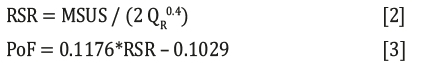
The McCracken and Stacey (1989) method of estimating rock mass stability requires that a RMC value, QR, be calculated for a geotechnical interval, which interval is in the order of 3 m long along the length of core (Peck et al., 1989) for a shaft investigation. Using this approach, the maximum stable unsupported span (MSUS) was estimated for face stability and wall stability in each interval according to the relationship:

where RSR is a risk term (raisebore support ratio), in which e.g. RSR = 1.3 relates to a tolerance threshold of 5% probability of failure for a ventilation shaft. It is understood that such a shaft is typically not equipped but is expected to provide a life-of-mine service function and therefore must not suffer excessive or premature failure.
Results of MSUS for one of the shafts are presented in Figure 2 showing the comparison between wall and face stability, and highlighting potential diameters of interest ranging from 1.8 m (pilot shaft) through to 6.0 m. The tendency for increased instability of the face in comparison with that of the shaft walls is evident from the chart; this may be expected intuitively, given that the advancing face presents a horizontal free surface more susceptible to failure under the influence of gravity than the vertical shaft walls. More importantly, areas of poor stability are consistent for both the face and shaft walls.
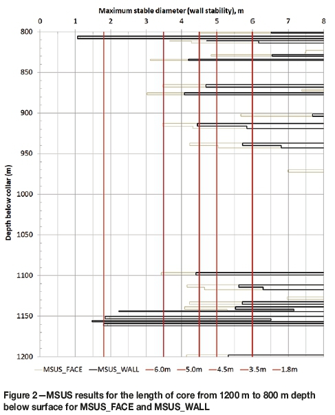
It is clear from the plotted results that over a 70 m length of the shaft, from 1165 m to 1095 m above the bottom collar, a zone of distinctly unfavourable ground persists, such that a shaft of no more than 1.8 m diameter will be stable in the worst case, or up to 4.0 m in the slightly less severe segments.
Also of importance is that between the shaft bottom and top collars, the final reaming diameter will no doubt be reduced in relation to the initial diameter at the shaft bottom collar. This is because as cutters are changed and the reamer is lowered and raised again, it becomes more and more difficult for the reamer to re-enter the shaft and resume reaming unless the cutter diameter is reduced to accommodate changes in the rock mass conditions. This must be taken into account during the planning of the shaft diameter requirements for ventilation (or other purposes) in that the rock mass conditions must be suitable for a larger diameter at the base of the shaft than at the top. In Figure 2, for example, a 6 m diameter shaft commencing at 1050 m would probably need to be successively reduced in diameter by some 0.15 m at 950 m and again at 925 m to successfully negotiate each difficult zone. The reamer diameter cannot be enlarged at a later point after it has been reduced at any stage without reaming from the start of the constriction to restore the diameter.
Standup times
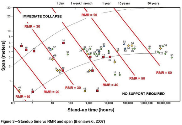
An estimate of the potential standup times for unsupported shaft walls was carried out according to Bieniawski's RMRBIENrelationship with excavation span (modified by Lauffer, 1988) (Figure 3. During the geotechnical core logging, parameters had been logged according to the Laubscher RMR90 classification method owing to the particular software that was being used. These parameters therefore needed to be translated into suitably corresponding input values compatible with RMRB1EN. This was achieved by a comparison of descriptors for the two methods and assigning values based on self-similar characteristics. This approach is not ideal and has the potential to result in an underestimation or overestimation of RMRBIEN by up to ten. The relationship between standup time, RMRBIEN, and excavation span is logarithmic, which means that a difference of RMRBIEN = 10 can change the interpretation from a standup time of one week (RMRBIEN = 40) to 1 year (RMRBIEN = 50) for a 6 m diameter shaft.
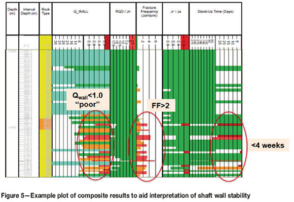
It is for this reason, among others, that no one parameter should be read in isolation, but the interpretation requires a side-by-side 'reading' of composite results, presented for example in Figure 5.
The minimum required standup time for a raisebored shaft was estimated using the application of Bieniawski, Celada, and Galera (2007) for tunnel boring. For both the standup time and excavation time estimates it is important to remember that the empirical methods were developed for horizontal tunnels. Some selective 'engineering interpretation' is therefore necessary to apply adjustments for vertical orientation with respect to geotechnical conditions.
Estimates of raiseboring advance rates also affect the interpretation of required standup time. As this is an area that appears still to be relatively loosely documented, there is scope to investigate this further. For this project, an average advance rate of 10.5 m was estimated for the shaft (accounting for variable advance rates as a function of lithology type) using the TBM approach of Bieniawski, Celada, and Galera (2007). However, in line with findings from available literature (Anderson and Cox, 1991; Hickson, 1998) and personal communication with contractors, an advance rate in the order of 3.5 m per day was planned and achieved. The TBM estimation approach was found to be not well suited to estimating raisebore advance rates in this case. Nonetheless, the outcome was that for a 1200 m long shaft, and the shaft walls would need to be stable for at least six months or more, which requires 'good' ground (Peck, Coombes, and Lee, 2011) for the site.
One of the sites that were rejected for the planned shaft location contained a total of 15 discrete locations, each in excess of 3 m long, distributed along the length of the shaft axis from 1200 m to surface, for which RMRBIEN < 45, i.e. less than one month standup time. This suggested that there was too high a risk associated with the site, and combined with the collective geotechnical indicators, presented a case for investigating an alternative location.
Stress-driven failure and SRF
The investigation into potential stress-driven failure or 'dog-earing' (spalling) through the selection of an appropriate stress reduction factor (SRF) was the subject of extended debate within the project. The SRF value is significant because it scales down the resulting RMC values by a factor that can range widely between a minimum of less than 2.5 and a maximum of more than 100, depending on the relationship between stress and rock strength. This has a major impact on the resulting rock mass class for the logging interval.
Based on somewhat limited local stress field information, the initial estimates of stress-driven failure potential led to overly conservative expectations of spalling potential. 1nitially, for the selection of an SRF value, the recommended approach of Peck, Coombes, and Lee (2011) was applied. The studies that comprise the empirical data of Peck, Coombes, and Lee (2011) are largely sourced from Australian locations, for which stress-driven effects are more telling than for this project located in South Africa. 1n contrast, observations of underground conditions on this project indicated that excessive stress-driven failure at depth (> 1000 m) was not to be expected. Similarly, results from the empirical estimate of dog-earing (spalling) using the approach of Martin, Kaiser, and McCreath (1999) also indicated greater potential for failure than observed on the operation. This created a conflict between 'theoretical' guidelines, field observations, and results from previous numerical analyses on the operation.
A serious outcome for the project was that the risk analysis based on stress effects appeared to be 'overly conservative' and created some uncertainty in interpreting the data. By applying the Australian approach too diligently in the initial investigation, it became apparent that the results were not in line with actual rock mass behaviour on the operation. As a result, it was necessary to adjust the analysis going forward, but not before this had had a disastrous effect for the project when one of the shafts was excavated in unsuitable ground, which is discussed in a subsequent section.
Going forward, estimates of stress-driven rock mass response based on the approaches of Peck, Coombes, and Lee (2011) and Martin, Kaiser, and McCreath (1999) were rejected based on local observations of rock mass behaviour at the operation. Instead, an SRF value for each logging interval was selected in accordance with Barton's guidelines for local 'shear' or weakness zones (Barton, 2002). This approach was regarded as more appropriate in this environment, in which failure is largely governed by gravity-driven kinematic failure.
Wedge failure potential
To obtain a reliable estimate of the potential for wedge failure, it was necessary to extract joint set information from the geotechnical investigation holes. This was carried out through a combination of local in-pit field mapping, downhole geophysics (televiewer logs), and vertical core orientation. Vertical core orientation frequently presents a 'rotational' error challenge. Also, in a magnetite-influenced environment such as this one, televiewer orientation can be similarly problematic, being reliant on magnetic orientation. However, within a limited extent of intervals, say, 50-100 m, it is considerably less important in a circular shaft to obtain 'absolute' orientations than relative orientations, given that the dip angle can be determined reliably relative to the horizontal. While the absolute orientations were not confidently established, it was nonetheless possible to generate size, shape, and factor of safety (FoS) distributions for potential wedge failures over limited intervals using the relative dip direction orientations, spacings, and joint surface conditions of the respective joint sets.
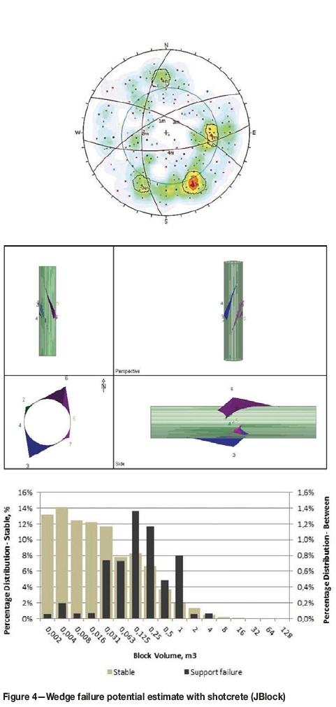
From this data, the maximum wedge sizes (using Unwedge, a Rocscience application(Figure 5) and probability distribution of potential wedge failures (using the application JBlock, Figure 4) (Esterhuizen and Streuders, 1998) were generated. Based on these results, it was concluded that without support, blocks in the order of 5 m3 (15 t) could be expected to fail. Investigations were carried out to assess the PoF for wedges greater than 1 m3 with or without shotcrete and with or without tendons (Figure 4). It was determined that with, say, shotcrete alone, up to 16% of all the failed blocks would be larger than 1 m3, whereas with tendon support, this would be reduced to 0.5%. Given that blocks larger than 1 m3 have a mass in excess of 3 t, this was significant and led to the conclusion that raiseboring in certain locations would not be feasible without support, and in particular, tendon support.
Note that JBlock analysis has a shortcoming for circular shaft stability analysis, since it generates only 'flat', not circular, release surfaces and does not account for the limiting effect on wedge width as a function of the circular shaft surface. Results obtained with JBlock were therefore compared against the Unwedge analysis to establish an upper limit for potential block failure volume.
Probability of failure (risk analysis)
An understanding of the probability of failure (PoF) goes hand in hand with an integrated reading of the suite of empirical results, which may be presented in several ways. For example, in Figure 5, various data columns stacked side-by-side illustrate the variability of stability indicators down the length of the hole.
Typically, these stability and excavability indicators include, among others, QR, MSUS, RQD/Jn (block size indicator), standup time, a stress factor (such as RCF), support requirements, and cutter life or boreability indices. Needless to say, the illustration can become somewhat crowded but it is helpful to obtain an overall impression of the shaft's PoF as a whole.
For this purpose, the McCracken and Stacey (1989) stability chart (Figure 1), as presented by Peck, Coombes, and Lee (2011), together with the relationship for MSUS (Equation [1]) was transformed to present an estimate of PoF for each logged interval along the length of the investigation hole (typically 3 m per interval, Equation [2] and Equation [3]). To translate the 'RSR' term to a PoF, the linear relationship (Equation [3]) was applied, based on RSR = 3.0 being equivalent to a 25% PoF and RSR = 1.3 equivalent to a 5% PoF. At this stage the PoF thresholds (25% and 5%) are selected directly from McCracken and Stacey's recommendations (1989); however, to more fully appreciate the associated risk consequence, it would be helpful to associate these risk terms with time and cost factors going forward.
The total length of shaft (m) affected by a certain PoF threshold (say, length of shaft with PoF > 5) for various shaft diameters, was generated (Figure 6). For example, at a particular site, for a 6 m diameter shaft, some 300 m was associated with a PoF > 5%, whereas at the same site, a 3.5 m diameter shaft would have only 80 m with the same PoF > 5%. For the same site, considering a threshold PoF > 25% (unacceptably high risk), some 70 m of a 6 m diameter shaft would be susceptible to this high potential for failure, whereas this would be reduced to around 20 m if the diameter is reduced to 3.5 m. Over a total shaft length of 1200 m, a reduction from 70 m (cumulative total affected length of shaft) to 20 m of unstable ground is sufficiently significant to affect the feasibility of a project. In this manner, it was possible to directly compare the apparent risk of failure associated with shaft diameters to assist in the decision-making process for the project.
Failure analysis (back-analysis)
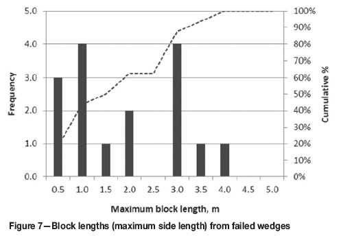
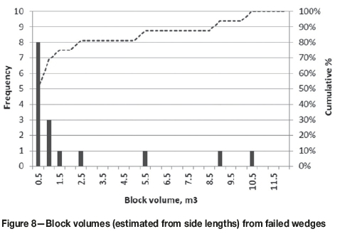
During the raiseboring of one of the large diameter (6.0 m) shafts for the project, severe failure was experienced which forced an abandonment of the site and revision of the project. An indication of the failure dimensions was obtained from visually recorded block sizes located on the muckpile at the base of the shaft (Figure 7 and Figure 8. Over a distance of some 100 m upwards from the bottom collar, blocks as long as 4.0 m, with volumes in excess of 5 m3 were found to have fallen from the sidewalls of the shaft, with yet more blocks being wedged on top of the reamer.
Several factors were identified as having contributed to this outcome, of which unfavourable rock mass conditions and support deficiencies at the base of the shaft (bottom collar) were noteworthy. An interactive state of unravelling appears to have occurred, commencing at the shaft bottom collar and migrating progressively upwards. A remote camera inspection revealed a cavity estimated to be 20-30 m or more horizontally across. 1t was not possible to determine with confidence whether the effects of brow failure and subsequent shaft sidewall failure were directly linked. This was because rock mass conditions appeared to be susceptible to failure within the shaft independently of the brow condition. Nonetheless, it was firmly established that stability of the shaft bottom collar is essential to maintain stable conditions and mitigate against progressive wedge failure away from the base of the shaft.
The presence of near-vertical discontinuities also contributed to excessive failure within the shaft. Steep-dipping discontinuities result in shaft wall instability and present a distinct risk to unsupported vertical sidewalls. 1t is difficult to identify these features during the geotechnical investigation stage due to the combined constraints of small hole diameter and the vertical (sub-parallel) axis of the drill-hole, which precludes intersections with steep-dipping structures. A detailed discussion on the optimum distribution of geotechnical investigation holes and investigation practices falls outside the scope of this paper. However, for a large-scale, potentially high-risk project, information from several differently orientated investigation holes is vital to avoid overlooking risks for the sake of reducing upfront costs.
For comparison, Figure 9 shows results for MSUS from two separate large-diameter shafts within the same operation in similar rock types and in a similar area. Both sets of results (Shaft A and Shaft B) indicate problematic conditions for a large (> 4.5 m) diameter shaft. However, Shaft A was successful (albeit not without significant challenges) while Shaft B was unsuccessful (this case study, Figure 5). The overall appearance of results for Shaft A indicates intervals in which the shaft walls will be unstable for diameters greater than 4.5 m. However, these intervals are confined to substantially shorter extents and are constrained within more competent intervals, in contrast with the indicators for Shaft A. During execution, Shaft A did indeed suffer some setbacks such as large wedge failure, including, towards the final stages, shearing of the reamer, and the last 30 m was completed by drop-raising. However, the shaft walls as a whole did not suffer extensive failure and in spite of the challenges, the shaft was completed successfully and remains stable following the application of shotcrete. Risk mitigating measures for Shaft B, incorporating in-line remote shotcrete application had been considered but could not be put into effect due to project and technology constraints (> 500 m length shaft).
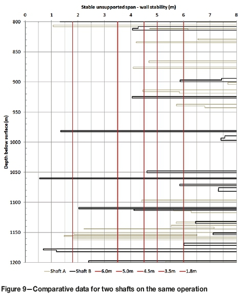
It is therefore perhaps easier to understand, in the context of 'successfully' completing Shaft A, as well as the difficult, yet successful, completion of an earlier shaft of similar dimensions (5.8 m diameter, 700 m length) within the same operation, that developing Shaft B by raiseboring may have seemed feasible. However, given the overall character of the data and outcome of the shaft boring attempt, it was made clear that even though previous projects may have been completed successfully, each location needed to be regarded in its own right for feasibility investigationss.
Selection of a suitable shaft sinking methodology
The selection of a suitable excavation method for a project is governed by a number of considerations which can be summed up as either financial (budget and timing) or practical (safety, technology, accessibility, and rock mass conditions). It is always necessary to work within the financial constraints of a project, or there would be no way forward. However, the practical constraints must be similarly regarded in their own right. 1n a project such as this, where several shafts with similar dimensions (diameter and length) had been successfully completed (albeit not without problems) using raiseboring, it was understandably difficult to consider that the same method may not always work, particularly given the demand for low-cost, rapid completion of a critical shaft.
Unfortunately, conditions within an operation may be variable, as encountered here, with the result that an alternative method of shaft excavation has to be considered. This remains the subject of a current investigation, the results and outcome of which will be presented in a future paper.
Conclusions
The analysis approaches of McCracken and Stacey (1989) together with insights of Peck and associates (Peck 2000; Peck and Lee 2007, 2008; Peck, Coombes, and Lee 2011) were successfully applied to the risk analysis of several planned and completed shaft vertical shafts within a particular underground expansion project. These empirical approaches have certain limitations; nonetheless, when applied with reasonable insight, the method was found to be effective and reliable for the estimation of geotechnical risk associated with a shaft sinking project.
In selecting an appropriate method for developing a large-diameter (> 4.5 m), long (> 500 m) shaft, it is important to remember that technological constraints in conjunction with geotechnical conditions must be considered equally deterministic for a project as timing and financial considerations. The suggested risk tolerance threshold put forward by McCracken and Stacey, i.e. PoF < 5% for an unlined, raisebored ventilation shaft, is still considered to be a reasonable criterion, beyond which alternative locations, risk indicators, or sinking methods must be considered.
1t is helpful and worthwhile to supplement the empirical analysis of rock mass stability with analyses such as susceptibility to wedge (kinematic) failure and stress-driven deformation, and these analyses should be carried out for any shaft-sinking investigation. 1n order to achieve this, orientated structural data should be gathered not only from vertical investigation holes sited as close as practically possible to the planned shaft axis (accounting for limitations associated with the sinking method), but also from inclined investigation holes to detect sub-parallel (near-vertical) structures. It is furthermore vitally important to take into account observations of local conditions, together with literature and numerical studies, in decision-making. For this project, the rejection of stress-based estimations of failure in favour of the influence of 'shear structures' (SRF) was considered to be appropriate.
Going forward, it would be of great value to supplement the available empirical database with records of successful and unsuccessfully raisebored shafts in the order of > 4.5 m diameter and > 500 m in length as part of a research initiative. This would assist in improving the overall understanding of the probability of success in large raisebore shaft projects, as diameters upwards of 7.0 m are being pioneered.
Acknowledgements
The author would like to thank the client and contractor(s) (unnamed) for allowing the work to be published and for providing their invaluable insights into the outcomes of the analysis.
References
Andersen, N. 2015. Pre-sink shaft safety analysis using wireline geophysics. Journal of the Southern African Institute of Mining and Metallurgy, vol. 115. pp.435-439, [ Links ]
Anderson, J.M. 1991. Optimisation of raisebore size. AusIMM Proeceedings, no. 1. pp. 39-43. [ Links ]
Barton, N. 2002. Some new Q-value correlations to assist in site characterisation and tunnel design. International Journal of Rock Mechanics & Mining Sciences, vol 39. pp. 185-216. [ Links ]
Barton, N.L. 1974. Engineering classification of rock masses for the design of tunnel support. Rock Mechanics, vol. 6, no. 4. pp. 189-236. [ Links ]
Bieniawski, Z.T. 1973. Engineering classification of jointed rock masses. Transactions of the South African Institution of Civil Engineers, vol. 15. pp. 335-344. [ Links ]
Bieniawski, Z.T. 1989. Engineering Rock Mass Classifications, a Complete Manual for Engineers and Geologists in Mining, Civil, and Petroleum Engineering. Wiley, New York. [ Links ]
Bieniawski, Z.T., Celada, Β., and Galera, J.M. 2007. Predicting TBM excavability. Tunnels and Tunnelling International, September. pp. 25-28 [ Links ]
Esterhuizen, G.S. and Streuders, S.B. 1998. Rockfall hazard evaluation using probabilistic keyblock analysis. Journal of the South African Institute of Mining and Metallurgy, vol. 98, no. 2. pp. 59-63. [ Links ]
Hickson, P.W. June 1988. Six metre raiseboring at Z C Mines. Proceedings of the AusIMM North West Queensland Branch, Underground Operators' Conference, June 1988. Australasian 1nstitute of Mining and Metallurgy, Melbourne. [ Links ]
Laubscher, D.H. 1990. A geomechanics classification system for the rating of rock mass in mine design. Journal of the South African Institute of Mining and Metallurgy, vol. 90, no. 10. pp. 257-273. [ Links ]
Martin, CD., Kaiser, ΕΚ., and McCreath, D.R. 1999. Hoek-Brown parameters for predicting the depth of brittle failure around tunnels. Canadian Geotechnical Journal, vol 36. pp. 136-151. [ Links ]
McCracken, A. and Stacey, T.R. 1989. Geotechnical risk assessment for large-diameter raise-bored shafts. Transactions of the Institution of Mining and Metallurgy, Section A: Mining Industry, vol. 98. pp. A145-A150. [ Links ]
Peck, W.A. 2000. Determining the stress reduction factor in highly stressed jointed rock. Australian Geomechanics, vol. 35, no. 2. pp. 57-60. [ Links ]
Peck, W.A. and Lee, M.F. 2007. Application of the Q-system to Australian underground metal mines. Proceedings of the International Workshop on Rock Mass Classification in Mining, Vancouver. pp. 129-140. N1OSH, Cincinnatti, OH. [ Links ]
Peck, W.A. and Lee, M.F. 2008. Stability of raise bored shafts in Australian mines. Proceedings of the 13th Australian Tunneling Conference. Australasian Institute of Mining and Metallurgy, Melbourne. pp. 331-337. [ Links ]
Peck, W.A., Coombes, Β., and Lee, M.F. 2011. Fine-tuning raise bore stability assessments and risk. Proceedings of the 11th AusIMM Underground Operators' Conference. Australasian 1nstitute of Mining and Metallurgy, Melbourne. pp. 215-226. [ Links ]
Stacey, TR. and Harte, N.D. 1989. Deep level raise boring - Prediction of rock problems. Proceedings of the ISRM Symposium: Rock at Great Depth, Pau, France. Maury, V. and Fourmaintraux, D. (eds.). Balkema, Rotterdam. pp. 583-588. [ Links ]
 Correspondence:
E.J. Walls
jwalls@srk.co.za
Received: 4 Sep. 2017
Revised: 24 Oct. 2018
Accepted: 14 Nov. 2018
Published: April 2019

