


Services on Demand
Article
 English (pdf)
 Article in xml format
 Article references
Indicators

Related links
-
 Cited by Google
 -
 Similars in Google
Share

 Permalink
Journal of the Southern African Institute of Mining and Metallurgy
On-line version ISSN 2411-9717
Print version ISSN 2225-6253
J. S. Afr. Inst. Min. Metall. vol.119 n.2 Johannesburg Feb. 2019
http://dx.doi.org/10.17159/2411-9717/2019/v119n2a1
DIAMONDS - SOURCE TO USE 2018 CONFERENCE
Kimberlite-country rock contact delineation at Finsch Diamond Mine
T. Khati; M. Matabane
Petra Diamonds, South Africa
SYNOPSIS
Accurate delineation of the contact between a kimberlite pipe and country rock at production level depths is a challenge due to limited geological data. Geological information is obtained from widely spaced diamond core boreholes which are drilled either from surface or from higher mining levels within the pipe. Kimberlite pipe/country rock contacts are notoriously irregular and variable, further reducing the confidence in contact positions defined by the drill-holes. At Finsch Diamond Mine (FDM), the opportunity arose to further improve the confidence in the contact positions relative to the planned slot (end) positions of each sublevel cave tunnel during the development stage of these tunnels. As a result, the accuracy of the 3D geological model has improved.
The use of diamond drill core for this purpose is expensive due to site establishment requirements. The lengthy time taken during site establishment also delays the development of tunnels and support cycles, thereby extending the completion dates. FDM has reduced delays during development by adopting percussion drilling, in conjunction with gamma ray logging. The S36 drill rig is mounted on a moveable platform and does not require a costly and lengthy site establishment. The holes are generally drilled (0°/flat) on grade elevation, and these holes could also be drilled from the rim tunnels (developed in waste) into the kimberlite pipe. A single-boom production drill rig is normally used to drill holes about 20 m in length.
On completion of the contact delineation drilling, gamma logging of the holes is conducted using the GeoVista geophysical sonde (or probe) to log the natural gamma signature of the dolomite/ kimberlite contact. The advantage of this tool is that the readings are continuous within centimetre intervals, and due to contrasting characteristics between kimberlite (rich in clay minerals) and dolomite, the contact position can be determined accurately. The better definition of contact positions also adds value to tunnel stopping distance in terms of developing the tunnel's slot at the optimum distance from the contact (easier blasting of longhole rings, avoidance of contact overbreak and premature waste ingress, and other matters relating to extraction of ore from these tunnels). This method is highly successful and has reduced development costs (on-time completion), improved definition of the pipe's contact position for geological modelling, improved blast design, and mitigated early waste ingress by maintaining the contact's integrity.
Keywords: natural gamma logging, contact delineation, kimberlite-dolomite contact, middling, waste ingress.
Introduction
The objective of the project is to establish the kimberlite-dolomite contact position with the intention of ensuring proper planning designs and management of waste during development. Contact delineation is performed with the intention of improving confidence in the resource model. The holes are drilled flat using a percussion drill and logged using a GeoVista geophysics tool. Geological information is available as soon logging is complete and the updated geological model is communicated to the production team. The main aims of the project are to reduce the time delay during contact delineation, and increase confidence in the position of the kimberlite-dolomite contact in an endeavour to fast-track the delivery of the development ends to caving. Kimberlite-dolomite country rock delineation is done from the rim tunnels or from within the kimberlite pipe in each tunnel. The aim of planning the mining tunnel and slot at the right location is to ensure stability of the tunnels and safe extraction of ore with no waste being accounted for. Secondary to this, delineation has enabled Finsch Diamond Mine (FDM) to locate the mudstone lenses found at the slot positions of the tunnels, thereby ensuring that slot positions are not established within an incompetent lithology.
Geological setting
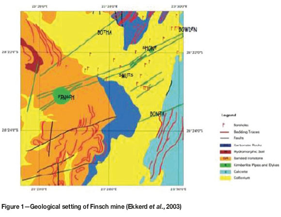
Finsch mine is located 160 km west-northwest of the city of Kimberley, South Africa. The kimberlite main pipe is a near-vertical intrusion with a surface area of 17.9 ha and is elliptical in outline. The main orebody occurs on a northeast-striking dyke called the Smuts Dyke and forms part of the Finsch kimberlite cluster, comprising the Finsch, Shone, and Bowden pipes (Ekkerd, 2005). It has been classified as a Group II kimberlite, with an age of 118 Ma. One of the characteristics of Group II kimberlites is a high potassium content.
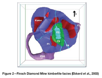
The Finsch kimberlite consists of eight main kimberlite facies, denoted F1 to F8 (Figure 2). The F5/F6 and F3 facies constitute the precursor bodies on the outer perimeter of the main pipe. These precursor bodies are mainly coherent kimberlite types. F1, F7, and F8 form part of the main pipe, with F1 and F8 being volumetrically the most significant units. F1, F7, and F8 are volcanoclastic kimberlite types. F2 and F4 occur as a hypabyssal plug and dykes within the main pipe and are postulated to represent the last stage of intrusion of the kimberlite (Ekkerd et al., 2003). Kimberlite magma, upon eruption, sampled Karoo and Transvaal Supergroup sediments, and these are now preserved in the main pipe as large xench'ths of basalt, mudstone, dolerite, and sandstone.
Literature review
In sublevel block caving the middling between the rim tunnels and the kimberlite-dolomite contact should not be more than 15 m to ensure tunnel stability in the SLC environment (Tukker et al., 2016). Moreover, the exact spatial location of the pipe contact is as important as that of the internal kimberlite phase contacts for ensuring the stability and integrity of the rim tunnels. The designs of rings were done based on trial and error or on the application of 'rule of thumb' (Onederra, 2004). Moreover, rings must function as designed, and it is important that engineers, geologists, and mine and plant managers have access to accurate modelling and simulation processes and cost-effective design parameters at the outset. According to Onederra and Chitombo (2007), the objectives of ring design include (but are not limited to) reduction of dilution and efficient orepass performance, therefore FDM decided to delineate the contact. The difference in blasting domains is a significant factor in ensuring proper ring designs and should be ascertained jointly by the geologist, geotechnical engineer, and drill and blast engineers.
Discussion
At FDM, the middling between the slot position and the kimberlite-dolomite contact is 7.5 m to 8 m. The reason for this middling is to achieve the best extraction of ore without damaging the contact. Rings are to be designed in such manner that the interaction with the contact is minimal, i.e. no damage to the contact and yielding more ore before waste ingression. Incompetent lithofacies such as mudstone compromise the stability of tunnels (Tukker et al., 2016), therefore the slot must be within competent lithofacies.
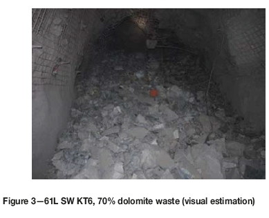
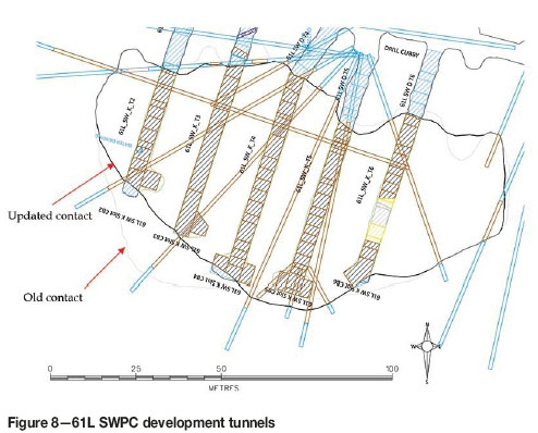
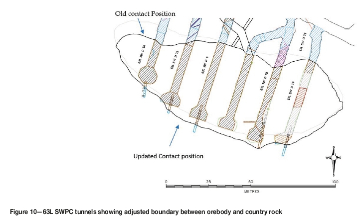
A different approach was taken when designing slot positions within the South West Precursor (SWPC). A 2 m middling was opted for as the SWPC is extremely competent hypabyssal kimberlite that provides easy caving. As a consequence, mining too close the country rock poses the risk of introducing large amounts of waste early (Butcher, 2000). Waste or dilution is better prevented than controlled as it threatens the viability of the mine, especially in SLC where up to 40% waste is encountered. To illustrate early introduction of waste, Figure 3 shows a slot ring reporting 70% waste rock upon the first blast. The irregular shape of the SWPC, poor mining practices, and failure to define the contact are the reasons for breaching of the kimberlite-dolomite contact on the 61 level. In contrast to the 61 level, the 63 level orebody boundary was redefined, with few tunnels breaching the contact (see Figure 8).
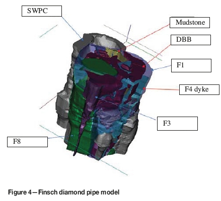
The SWPC (F5/F6) is coherent/hypabyssal, competent kimberlite. Figure 4 shows the kimberlite facies at Finsch mine relative to the country rock (dolomite); there is dolomite situated between the main pipe and SWPC. Finsch mine utilizes vertical and inclined dump ring designs. In addition to raiseboring, vertical dump is used to initiate free fall of ore flow. Experience has shown that a correctly designed middling will enable proper ore caving with less damage to the contact, which is already brecciated/broken, thus ensuring minimal unplanned waste ingress and ring designs to within ±1-2 m. In addition, the correct middling will enable a ring dump not less than 45°. A flatter angle will make charging and ore extraction difficult because of the flat repose angle (Bullock and Hustrulid, 2001). The steeper the angle of repose, the better the extraction due to the flow of ore under gravity. Proactive waste management practices during the development of tunnels are crucial to ensure that the rings continue to hold back excessive waste ingression. Dilution and ore losses are drawbacks for sublevel caving.
Scientific investigations have been conducted to determine the flow of ore in a cave and to identify means of reducing ore losses and minimizing dilution. Dilution varies between 15% and 40% and ore losses can be from 15% to 25%, depending on the geological conditions. Dilution is of less importance for orebodies with diffuse boundaries where the host rock contains low-grade mineralization, or for magnetite ores, which are upgraded by simple magnetic separators (Hamrin, 1986). The geology department at FDM conducts visual estimations to determine waste percentages in the drawpoints which, coupled with delineation, effectively controls excessive waste mining and loading.
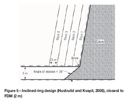
Mathebula (2004) estimates 70% waste ingression towards the end of the block 4. The dolomite sidewalls ravel back to a stable angle, and large volumes of waste will report to the bottom, which will result in low grade due the mixing of dolomite and kimberlite. Bull and Page (2000) characterize sublevel caving as a compromise between ideal layouts and what the orebody allows. For this reason, the mine engineers tend to focus on immediate development costs and conclude that less development is cheaper, thereby overlooking the negative effects on head grade (due to planned and unplanned dilution) and loss of production. The mine plan should consider dilution and production as the most significant factors in mine design layout. During production, the rings must be inclined (10-20°) to prevent waste from being drawn in early before most of the ore material is loaded (Figure 5).
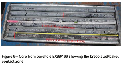
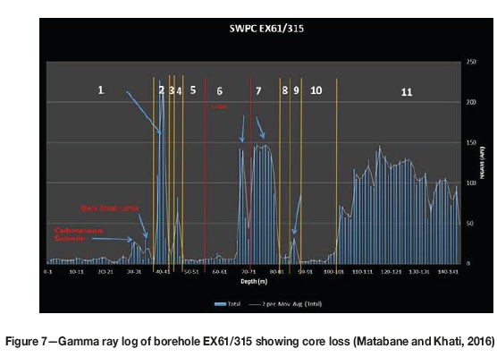
Kimberlite-country rock delineation was adopted at Finsch with the intention of reducing development costs such as that due to breached contact support. Figure 6 shows tunnels where the contact was breached which resulted in an increase in mining cycle time, costs, and reinforcement requirements (class 7 support) (Onederra, 2004). As a result of breaching contacts, there will be high waste ingress in comparison with what the waste ingress model of Page and Bull (2001) predicts (70-80%) at the end of caving. As an illustration, Figure 3 shows 70% waste vs 80% ore recovery. The need to delineate the kimberlite-country rock contact was shown by the irregularity of the SWP, and poor drilling and blasting practices which resulted in contact positions not being at the anticipated position (see Figure 8). Delineating the contact improves geological confidence in the model and compensates for the core losses encountered during drilling as a result of core handling errors and bad ground conditions (Figure 6). Four out of five tunnels intersected the kimberlite-dolomite contact unexpectedly. If the contact is not delineated accurately, tunnels are blasted through the contact, thereby damaging about 2 m of the baked and brecciated contact margin or zone (Figure 7).
Specifically, the visual estimation performed in 63L SW KT6 slot resulted in 70% waste vs kimberlite. Contact delineation has increased confidence in the resources even though there has been a volumetric decline, as shown by the previous contact position (grey vs black outline in Figure 8).
The irregular shape of the SWPC and core loss during diamond drilling is compensated with the use of contact delineation (Figure 8). FDM experienced poor mining practices on 61 level, as shown by Figure 8, as four out of five tunnels breached the kimberlite-dolomite contact. In order to implement correct principles in controlling waste, there is a need to define waste, i.e. top, side, or internal. The reduction is by definition, design, and draw principles. Unsupported mining in massive orebodies tends to lead to high waste or dilution (40%) (Kosowan, 1999), and dilution increases with more muck being extracted.
Mine design is critical as it impacts on development costs, drill and blast, recovery, and geotechnical stability, i.e. where the stress field orientation and rock mass quality influence the mine design. FDM experiences both internal and side dilution, hence contact delineation is aimed at preventing or reducing early ingress of waste. As identified by Butcher (2000), the define, design, and draw principle is aimed at preventing dilution rather than controlling it. However, if prevention fails, controls must be put in place. The FDM geology department conducts visual inspections on a daily basis.
According to Butcher (2000), the define principle is geologically significant in delineation of the orebody and surrounding country rock. Geology must determine the boundaries of country rock and orebody. Following the design principle, FDM set the boundary at 7.5-9 m between the orebody contact and stope boundary. This measure will reduce the side and internal dilution through better ring designs and better blasting practices. In addition to prevention principles, FDM conducts daily visual estimations as a control measure in the drawpoints and scanline logging during tunnel mapping.
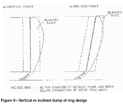
Figure 9 shows ring designs used at FDM and their benefits, i.e. a vertical front is used to initiate the rings and inclined rings have the potential to delay introduction of waste from above, and shield brows from break-back. When designing rings in an SLC mining method, it is important to consider lithology, density, and grade (Mathebula, 2004). Development should take place in competent rocks to accommodate mining-induced stresses. Mudstone is incompetent, hence FDM avoids the development of slots within the mudstone facies. Slot position is dependent on the rock mass conditions, stope access, and extraction sequence. The slot should also be designed to reduce failure within the production rings (Villaescusa, 2014). Support should be increased when mining through incompetent ground (Mzimela, 2013). Finsch kimberlite facies are hard, but upon interaction with water they become as weak as soil; thus the strength is compromised upon exposure to moisture. The emplacement mechanism influences the size and geometry, rock mass competency, and character of the pipe contact zones. These factors affect the mining method and dilution. Characterizing the clay provides important clues to the susceptibility of the various kimberlite facies to weathering. Knowledge of country rock and pipe geology is paramount. Delineation programmes should aim to ensure that the holes penetrate deep enough into the waste rock to ensure it is not a country rock xenolith. One of the geotechnical issues to consider in selecting the mining method and design is the strength and deformation characteristics of the rock mass. Some kimberlite facies are weak to moderately strong. Designing in a strong rock mass is not an issue; however, when kimberlite is exposed to moisture, swelling of smectite clays present in the matrix weakens the rock. The weathering susceptibility of kimberlite must be known in order to build this factor into the mine design and avoid surprises during development, such as a tunnel collapses due to water.
Geotechnically, it is important to know the lithology being mined, especially as regards density and other properties. A 2 m offset or standoff is considered when designing rings within tunnels next to the kimberlite-dolomite contact. This is important in ensuring that minimal waste is allowed into the cave and there is no damage to the kimberlite-dolomite contact.
The inclination of rings is 10 to 20° forward to assist in feeding the ore prefentially into the drift by providing a small overhang to diluting material above (Darling, 2011). The inclination is to ensure that holes are drilled on a similar plane for improved blasting results and additional protection of the brow. Inclined brows improve stability and access for charging of the holes. Safety is another reason for inclined ring designs (Kosowan, 1999). In addition, the gradient depends on the relative size and densities of ore and waste rocks. When ore material is coarser than waste material, the dump must be tilted backwards to avoid fine ore material being lost in the void of blasted waste rock (Kosowan, 1999).
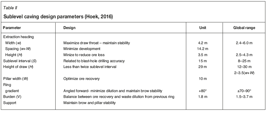
A forward inclined ring is best for ensuring good breakage of rock blocks and would avoid crossing discontinuities that could potentilly result in cut-offs and poor fragmentation. The purpose of the slot position is to provide a free face when blasting (Table II and Hoek, 2016). The Karoo sediments found within the main pipe and in the SWPC make drilling ahead of the development tunnels a necessity. Mine planning and design flexibility is needed to accommodate changes in the modelled lithological units and their effects on the geotechnical and resource model (Tukker et al., 2016). The middling between rim tunnels and actual contacts should not be less than 15 m to ensure stability of rim tunnels. Geotechnically, sublevel caving requires specific rock mass conditions and stoping geometry; ring drilling may vary and involve or include upholes, downholes, and even inclined holes (Villaescusa, 2014).
Figure 8 shows 61L which intersected the dolomite contact prematurely due to a sharp inward turn of the contact. The 61L SW KT6 is situated between tunnels 8 and 9; contact holes were not drilled beforehand and 'blind' mining was undertaken in this case. This sharp turn or curve is believed to be the reason for the 70% waste ingress when the first ring was blasted. Contact drilling could have mitigated this issue. In order to implement working waste control measures, the type of waste must be known - namely; top, side, and internal waste. This will lead to waste reduction by defining, designing, and drawing (Butcher, 2000).
The middling between the slot position and the contact should be 7.5-8 m. Therefore, owing to the four tunnels intersecting the contact, early waste ingress was experienced when the rings were blasted. This should be avoided at all costs as failure to drill in advance results in mining through the contact. In addition to the sharp inward turn of the contact from previous position, waste ingress was compounded by the type of ring design. An inclined front reduces ingress of waste as it prolongs ore extraction. Moreover, contact delineation helps in ensuring that pockets near contacts are found and properly supported. Pockets of water reduce the stability of the kimberlite-dolomite contact, rendering it weak. The cost of blasting and supporting was high when contact delineation tunnels were developed blindly into the country rock, resulting in unnecessary expenditure.
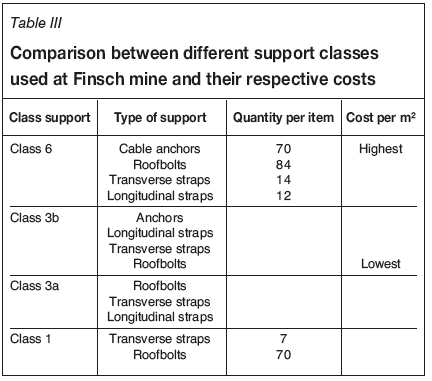
This wastage is in the form support equipment, where for example class 6 is used instead of class 1 (class 6 support is three times the cost of class 1 support). Historically, drilling to confirm inner geological contacts has been an expensive, challenging, and time-consuming exercise. However, at FDM short percussion holes about 30 m in length have been drilled to delineate the contact, with an information turnaround time of less than 24 hours. Contact delineation has afforded FDM with information regarding lithological units and enabled quick decisions such as whether to extend a tunnel or keep to the original design. In addition, where mudstone was intersected slot positions have been moved to a more competent kimberlite facies
Conclusions
Finsch Diamond Mine experienced challenges relating to SLC development tunnels where the kimberlite-country rock contact was breached, resulting in increased development and support costs which in turn led to delays in turnaround times (mining cycle). Drilling a single contact delineation hole per tunnel is found to be workable; however, two to three holes are ideal to ensure covering all sides of the slot area. In order to avoid delays in drilling for the contact, monthly planning should incorporate the delineation holes and the planning and survey departments need to include these holes when issuing survey notes. In the case of tunnels breaching the contact, as shown by Figure 8, penalties should be implemented. Therefore, two to three percussion holes approximately 7.5-8 m in length should be drilled per tunnel. Contact delineation has resulted in cost savings, especially regarding waste reduction. Furthermore, early waste ingress was experienced in certain areas of the mine as a result of breached kimberlite-dolomite contacts. Knowledge of the position of the contacts increased the confidence in resources, as shown by Figure 8 and Figure 10, and geological boundaries were adjusted accordingly. At Finsch Diamond Mine, waste ingress is the result of poor mining practices and incompetent ground conditions. The geology department, through contact delineation, has prevented dilution early on rather than controlling waste, with cost savings estimated to be in the millions. As part of enforcement, financial penalties should be put in place to ensure that mining contractors do not breach the kimberlite-dolomite contact. In addition, monthly planning must take the drilling of these contact holes into consideration.
References
Bull, G. and Page, C.H. 2000. Sub-level caving - Today's dependable low cost "ore factory". Proceedings of Massmin 2000, Brisbane, Australia. Australasian Institute of Mining and Metallurgy, Melbourne. pp. 537-556. [ Links ]
Butcher, R.J. 2000. Dilution control in Southern African mines. Proceedings of Massmin 2000, Brisbane, Australia. Australasian Institute of Mining and Metallurgy, Melbourne. pp. 1133-118. [ Links ]
Dustan, G. and Power, G. 2011. Sub level caving. SME Mining Engineering Handbook. Darling, P. (ed.). Society for Mining, Metallurgy & Exploration, Littleton, CO. pp. 1417-1452. [ Links ]
Ekkerd, J. 2005. The geology of the block 5 resource. Internal Report. Finsch Diamond Mine. [ Links ]
Ekkerd, J., Stiefenhofer, J., Field, M., and Lawless, P. 2003. The geology of Finsch Mine, Northern Cape, South Africa. Proceedings of the 8th International Kimberlite Conference, Victoria, BC, 22-27 June 2003. Elsevier, Amsterdam. [ Links ]
Hamrin, H. 1986. Guide to Underground Mining Methods and Applications. Chapter 1. Atlas Copco, Sweden. [ Links ]
Hoek, E. 2016. Surface and underground project case histories: Comprehensive Rock Engineering: Principles, Practices, and Projects. vol. 5. Elsevier. [ Links ]
Hustrulid, W. and Kvapil, R. 2008. Sublevel caving - past and future. Proceedings of the 5th International Conference and Exhibition on Mass Mining, Luleá, Sweden, 9-11 June 2008. Lulea University of Technology. pp. 124-132. [ Links ]
Kosowan, M.I. 1999. Design and operational issues for increasing sublevel cave intervals at Stobie Mine. MASc thesis, Laurentian university, Sudbury, ontario, Canada. [ Links ]
Matabane, M.R. and Khati, T. 2016. Application of gamma ray logging for kimberlite contact delineation at Finsch Diamond Mine. Proceedings of Diamonds Still Sparkling, Gaborone, Botwsana, 15-16 March. Southern African Institute of Mining and Metallurgy, Johannesburg. [ Links ]
Mathebula, V. 2004. The design and implementation of the Toop of Block 4(TOB 4)/ BOP resource at Finsch Mine (a division of central mines). Journal of South African Institute of Mining and Metallurgy, vol. 104. pp. 163-170. [ Links ]
Mzimela, B. 2013. Code of Practice: The design, development/construction, safe operation and maintance of draw points, tipping points, rock passes and box. Lime Acres. [ Links ]
Onederra, I. 2004. Breakage and fragmentation modelling for underground production blasting application. Proceedings of the IRR Drilling and Blasting 2004, Conference. Perth, WA. [ Links ]
Onederra, I. and Chitombo, G. 2007. Design methodology for underground ring blasting. Mining Technology, vol. 116, no. 4. pp. 180-195. [ Links ]
Page, C.H. and Bull, G. 2001. Sub level caving: A fresh look at this bulk mining method. Underground Mining Methods: Fundamentals and International Case Studies. Hustrulid, W.A. and Bullock, R.L. (eds). Society for Mining, Metallurgy, and Exploration, Littleton, Co. p. 718. [ Links ]
Tukker, H., Marsden, H., Holder, A., Swarts, B., van Strijp, T., Grobler, E., and Engelbrecht, F. 2016. Koffiefontein Diamond Mine sublevel cave design. Proceedings of Diamonds Still Sparkling, Gaborone, Botwsana, 15-16 March. Southern African Institute of Mining and Metallurgy, Johannesburg. [ Links ]
Villaescusa, E. 2014. Geotechnical Design for Sublevel Open Stoping. CRC Press. [ Links ] ♦
This paper was first presented at the Diamonds - Source to Use 2018 Conference, 11-13 June 2018, Birchwood Hotel and OR Tambo Conference Centre, JetPark, Johannesburg, South Africa.

