


Serviços Personalizados
Artigo
 Inglês (pdf)
 Artigo em XML
 Referências do artigo
Indicadores

Links relacionados
-
 Citado por Google
 -
 Similares em Google
Compartilhar

 Permalink
Journal of the Southern African Institute of Mining and Metallurgy
versão On-line ISSN 2411-9717
versão impressa ISSN 2225-6253
J. S. Afr. Inst. Min. Metall. vol.118 no.12 Johannesburg Dez. 2018
http://dx.doi.org/10.17159/2411-9717/2018/v118n12a2
PAPERS OF GENERAL INTEREST
Explicit representation of rock reinforcement in 3D DEM models for foliated ground
E. KarampinosI; J. HadjigeorgiouI; M. PierceII
IUniversity of Toronto, Canada
IIPierce Engineering, USA
SYNOPSIS
One of the main challenges in the numerical modelling of ground support in underground excavations is to reproduce the performance of the sequential installation of the reinforcement while capturing the rock mass behaviour of an advancing face in 3D. The 3D modelling approaches used to simulate the progressive advance of excavations are mostly continuum and often cannot reproduce the rock mass failure mechanisms. The 3D discrete element method (DEM) can better reproduce structurally controlled rock mass failure mechanisms and can explicitly represent the reinforcement elements. This paper builds on previous work that reproduced the structurally controlled squeezing conditions in an underground hard-rock mine using 3D DEM and the in situ behaviour of reinforcement under pull conditions. It addresses important issues on the way reinforcement is explicitly introduced in discrete element models. A pseudo-3D model is employed to overcome the computational restrictions and time limitations of a 3D modelling approach. The work focuses on the scaling of the material properties of the ground support elements when the thickness of the model is not equal to the out-of-plane spacing of reinforcement. It demonstrates the scaling methodology based on the type of the modelled reinforcement elements used and investigates the significance of this approach. The advantages and disadvantages of this approach with respect to 2D and 3D methods are discussed. The results are compared with field data and previous modelling work done at the mine.
Keywords: rock reinforcement, discrete element method, squeezing ground.
Introduction
Numerical models can provide significant insight into the anticipated behaviour of underground excavations. The modelling of ground support, however, is not a trivial exercise. An effective representation of ground support in underground excavations should capture the behaviour of both the rock mass and the support elements. When numerical models are used for design purposes, the complexity of the problem requires significant time and expertise (Sweby, Dight, and Potvin, 2016).
At a laboratory scale, numerical models have successfully reproduced the results of laboratory tests on rockbolts by explicit modelling of the bolt, the borehole, and the grout. Chen and Li (2015) used a continuum FLAC3D (Itasca Consulting Group Inc., 2012) model to simulate the mechanical behaviour of D-bolts as observed experimentally. Grasselli (2005) used a 3D finite element code to model the behaviour of fully grouted rods and expandable bolts under shear.
At a larger scale, 2D models are most commonly used to capture the behaviour of ground support around excavations. The most severe limitation of these models is the difficulty in taking into account the sequencing of the excavation and the support installation during excavation (Lorig and Varona, 2013). Three-dimensional models can simulate explicitly the progressive advance of excavations. These models are mostly continuum (Vlachopoulos et al., 2013; Vakili et al., 2013; Perman et al., 2007; Beck, Kassbohm, and Putzar, 2010).
This paper builds on previous modelling work using the 3D discrete element method (DEM) to analyse structurally controlled deformations and investigates different ways to represent reinforcement. The previous work demonstrated that 3D DEM models can successfully capture the buckling and squeezing mechanisms observed in underground hard rock mines (Karampinos et al., 2015). The method allows for a more refined consideration of the role of fractures within the rock mass, including rotation of separate blocks, opening of fractures, and detachment of blocks from their initial position. The interaction of the separate blocks with the reinforcement is also modelled explicitly.
The representation of reinforcement in numerical models depends on whether the tunnel is modelled in 3D, pseudo-3D (a slice of finite thickness) or 2D. 3D models can simulate explicitly the timing of support installation relative to the incremental advanceme of the face, which is important to capture in cases where the support is installed close to the face. Computational restrictions and time limitations often do not allow for 3D modelling, and so techniques have been developed to account for the impact of tunnel advance in both pseudo-3D and 2D modelling approaches, such as the pressure reduction or face de-stressing methods (Vlachopoulos and Diederichs, 2014). Previous work presented by Karampinos, Hadjigeorgiou, and Turcotte (2016) used the pressure reduction method in 3DEC to capture the impact of tunnel advance on the effectiveness of reinforcement in managing structurally controlled deformations at the LaRonde mine.
While a pseudo-3D model offers the advantage of providing some insight into the variability in deformation control that the reinforcement provides in the out-of-plane direction, scaling of the ground support element properties (and emergent forces) is generally still required, unless the thickness of the model is set equal to the out-of-plane spacing of the ground support. Such scaling must always be used in 2D models, where the effect of ground support must be averaged over the actual spacing between elements in the out-of-plane direction (see, e.g. Donovan, Pariseau, and Cepak, 1984; Itasca Consulting Group Inc., 2014). The choice between 2D, pseudo-3D, and 3D models is dictated by problem geometry, computational restrictions, etc.
This paper addresses important issues on the way reinforcement is explicitly introduced in distinct element models. It focuses on a case where a pseudo-3D model of fixed thickness (not equal to the out-of-plane spacing of reinforcement) was employed. This necessitated scaling the properties of the reinforcement elements according to the modelled, versus true, spacing. The work illustrates the methodology of scaling the mechanical properties based on the type of the reinforcement elements used, with particular focus on the performance of rebars, friction rock stabilizers, and hybrid bolts. The advantages and disadvantages of this pseudo-3D approach (as opposed to purely 2D or 3D) are discussed and the results are compared with field data and previous modelling done at the LaRonde mine.
Capturing the performance of reinforcement in in situ pull-out tests
The mechanical behaviour of reinforcement elements can be modelled in a 3D DEM, such as 3DEC, using structural elements. Global reinforcement elements can be used successfully to simulate the performance of the different bolts used at LaRonde (Karampinos, Hadjigeorgiou, and Turcotte, 2016). These elements are assumed to be divided into a number of segments. Nodal points are located at the end of each segment. They can simulate the resistance to pull-out that results from the combined effect of shear forces developing at the interface between the reinforcement and the rock or the grout and the axial stiffness of the steel itself. The first part is accounted for by a spring-slider system at each of the nodal points. A maximum limit can be assigned to the shear force developed per unit length of element. A spring is also located between the nodal points to simulate the axial behaviour of the steel. An axial stiffness, a tensile strength, and a strain limit can be assigned to the element (Itasca Consulting Group Inc, 2013).
Karampinos, Hadjigeorgiou, and Turcotte (2016) calibrated material properties, simulating the performance of the reinforcement elements used at LaRonde based on in situ pull-out tests. The calibrated material properties for the rebars, friction rock stabilizers (FRSs) and hybrid bolts used at the LaRonde mine are shown in Table I. An elastic-plastic material behaviour was assigned to the spring-slider system that represented the bonding between the blocks and the structural elements at the nodal points. The elastic behaviour of this system was controlled by the bond stiffness assigned to the elements. The cohesive strength of the bond applied a limit to the shear force developed per unit length of element. The elastic behaviour of the steel, represented by a spring between the nodes, was controlled by the Young's modulus assigned to the elements. A tensile yield strength and a strain limit were assigned to the spring to represent the yielding of the steel and bolt rupture respectively.
A hybrid bolt is a rebar installed inside a FRS. This setup can be easily installed in fractured ground and results in an increased loading capacity compared to a FRS without rebar, Turcotte (2010). The performance of the hybrid bolt under axial load using the global reinforcement elements is shown in Figure 1 as an example. The graphs show that when the peak axial load is reached, the bolt starts to slide. After that point, the bolt continues to slide under a constant load while the tensile capacity of the element is not exceeded. The FRS stabilizer has a similar mechanical behaviour with low loading capacity.
A different behaviour was assigned to the elements representing the rebars. It was assumed that the nodal points could not slide, while the elements between the nodes could stretch. When the bolt reaches its axial capacity, plastic deformation occurs and the bolt ruptures when the strain limit is reached (Karampinos, Hadjigeorgiou, and Turcotte, 2016).
Field observations from squeezing conditions at LaRonde mine
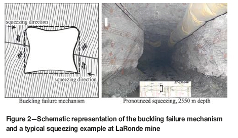
The buckling mechanism at LaRonde has been described by several authors (Potvin and Hadjigeorgiou, 2008; Mercier-Langevin and Wilson, 2013; Karampinos et al., 2015). Figure 2 shows a schematic representation of the mechanism and a typical squeezing example at 2550 m depth. In thinly foliated ground, the stress redistribution around the excavation results in axial loading of the rock slabs. This causes contraction along the foliation and dilation orthogonal to the foliation planes. The dilation decreases the critical buckling load. As buckling occurs in the walls the process propagates deeper into the rock mass. The direction of squeezing is normal to the foliation planes.
The performance of reinforcement elements at LaRonde mine
Figure 3 demonstrates the recorded impact of the hybrid bolts at the LaRonde mine. Borehole extensometers were installed in the back and the north wall at 2690 m approximately one week after the excavation of the examined section. The measurements presented in Figure 3a showed that the introduction of the hybrid bolts and straps reduced the displacement rate, although they did not completely arrest the deformation. The extensometers were subsequently sheared due to excessive deformation. For practical purposes, when a drift becomes less than 3.5 m wide, the excess and fragmented rock is removed by 'purging' the walls. Figure 3b shows the significant reduction of the purging distance after the introduction of the hybrid bolt and straps as a secondary support strategy. This distance was defined as the length of the drift sections requiring purging of the walls in a direction parallel to the direction of mining (Karampinos, Hadjigeorgiou, and Turcotte, 2016).
Implementation of global reinforcement elements in modelled squeezing conditions
The construction of a true 3D numerical model using the DEM was not a practical option due to computational and time limitations. The constraints have been discussed by Karampinos et al. (2015), who therefore decided to construct a pseudo-3D model. The option implemented was to model a thin slice of a drift. The constitutive models used to reproduce the squeezing mechanism have been described by Karampinos et al. (2015). The progressive reduction of the forces acting at the boundaries of the excavation in the model captured the deformation changes resulting from tunnel advance as observed in the field.
The pressure reduction method was used to introduce the calibrated global reinforcement elements at different deformation stages following the same sequence used at LaRonde. The forces acting at the boundaries of the excavation were progressively reduced by a reduction factor (r) through a series of modelling steps. This method provides a longitudinal displacement profile (LDP) indicating the progressive displacement for each wall and allows modelling of the sequential installation of reinforcement at different deformation stages. The face of the excavation is considered to be ahead of the modelled section when the reduction factor is equal to unity. As r reduces, the face approaches the modelled section and overpasses it. At the final modelling stage the reduction factor is equal to zero and the face has no effect on the modelled section. The model reached equilibrium at the last modelling stage in all the examined cases. The modelling steps are not directly related to actual steps of a 3D advancing face.
Figure 4 shows the model geometry and the modelled squeezing conditions in LaRonde prior to the introduction of reinforcement in the model. The employed technique captured the progressive extent of joint slip and plastic zones around the opening as observed in several squeezing case studies and indicated a direction of squeezing normal to the foliation planes. The model captured the rotation and detachment of the rock blocks and the opening of the fractures. The direction of squeezing is normal to the foliation planes and the extent of joint slip follows the same trend.
A series of reinforcement cases was originally examined and has been presented by Karampinos, Hadjigeorgiou, and Turcotte (2016). It was ascertained that the use of a hybrid bolt as a secondary support strategy reduces the bulking of the tunnel sidewalls and can decrease the required rehabilitation. The representation of variability in deformation control (by reinforcement) in the out-of-plane direction in these cases was limited to the thickness of the modelled slice. This work investigates the impact of using unscaled versus scaled material properties for the reinforcement elements at LaRonde in the pseudo-3D model.
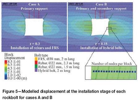
This work focuses on two cases investigating the 3D impact of primary and secondary reinforcement at the LaRonde mine. The mine has recognized, based on empirical experience, that under squeezing conditions the reinforcement is best installed in stages. In case A, primary support comprising rebars in the back and FRSs in the sidewalls was installed at r = 0.3 (stage 6). In case B, in addition to the primary support, secondary support was installed in the sidewalls at r = 0.15 (stage 8). Figure 5 shows the modelled displacement at the installation stage when the reinforcement elements were added using the calibrated material properties. The reinforcement elements were installed in the middle of the 0.05 m thick model. A bond strength ten times higher than that presented in Table I was assigned to the first node of each global reinforcement element to simulate the effect of a plate on each bolt. The elements were not pre-tensioned.
3D impact of the discrete effect of reinforcement
The impact of linear scaling of the reinforcement material properties was examined to account for the fact that the pseudo-3D model thickness in this case is not equal to the true out-of-plane spacing of the reinforcement. This approach averages the effect of reinforcement in 3D and takes into account the out-of-plane spacing of reinforcement (i.e. along the tunnel axis) (Itasca Consulting Group Inc, 2014).
The impact of the reinforcement in a 0.6 m out-of-plane spacing was examined based on the spacing used at LaRonde. The calibrated material properties of the global reinforcement presented in Table I were linearly scaled to distribute the discrete effect of the bolts in the out-of-plane direction.
The material properties of the structural elements were divided by 12 to account for a 0.6 m spacing in the 0.05 m thick discrete element model. For the FRS and the hybrid bolt, the parameters scaled were those controlling the axial force and the shear force of the elements, namely the Young's modulus, the tensile yield strength, the bond stiffness, and the cohesive strength of the bond. For the rebar, the parameters scaled were those controlling the axial force of the elements and the shear stiffness. Based on the calibration of the elements, as discussed previously, and the modelled failure mechanism, it was assumed that the bolts do not slide at the anchorage points in both scaled and non-scaled cases. Therefore, the cohesive strength of the bond was not modified. The scaled material properties for the FRS, the hybrid bolt, and the rebar are shown in Table II. These properties were used in the reinforcement scenarios from cases A and B.
Impact ofprimary support on the displacement
Figure 6 shows the modelled displacement and the performance of rockbolts for case A (when only primary support was introduced to the model) using scaled and non-scaled material properties. The reduction of the displacement in the hangingwall when non-scaled properties were used was 4%, whereas when scaled properties were used, there was no reduction of the displacement. The failure in rebars in the back, when scaled properties were used, was reasonable given the lower material properties used. The bonds of the rebars in the back remained intact in both cases while the bonds of the FRSs failed in both cases, resulting in sliding of the bolts.
In interpreting the results of the axial forces generated by using scaled elements, it is recognized that these are influenced by the reinforcement modelling strategy. In effect, instead of employing widely spaced elements, closely spaced elements with scaled properties were used to capture the same reinforcement effect that would be obtained by using widely spaced elements. Consequently, the axial forces shown in the right-hand side of Figure 6 are the result of using tightly spaced scaled elements. In order to extrapolate these results to obtain the emergent forces that would result with the use of widely spaced elements, it would be necessary to multiply the forces on the right-hand side in Figure 6 by 12 (0.6/0.05). This would actually result in higher axial forces as the elements are more widely spaced in the out-of-plane direction (i.e. each rockbolt must therefore take more load).
Impact ofsecondary support on the displacement
Figure 7 shows the final modelled displacement and the performance of rockbolts for case B using scaled and non-scaled material properties. In this case, hybrid bolts were introduced to the sidewalls after the installation of the primary support and after some initial displacement had occurred. The modelling results from when non-scaled properties were used are shown as a reference. When non-scaled properties were used, the reduction of the displacement was 18%. When scaled properties were used, the reduction of the displacement was 10%. The model reached equilibrium at the last modelling stage (step 13) in all the examined cases. The plots illustrate that the bonds of the FRSs and the hybrid bolts failed to a greater extent when scaled properties were used, due to the lower bond strength assigned to the elements. The results are logical.
Figure 8 shows the combined interpretation of the LDP for the centre of the hangingwall (left wall), the footwall (right wall), the back, and the floor. The results from all the walls indicate similar trends. Scaling the material properties averaged the effect of reinforcement in 3D and increased the modelled displacement for each case. The modelled displacement was higher when scaled material properties were used than when non-scaled properties were assigned to the bolts. The modelled displacement using scaled and non-scaled properties indicated the same trends. The introduction of hybrid bolts as part of a secondary support strategy contributes to a significant reduction in drift convergence.
Non-scaled elements show a larger reduction in displacement. The results obtained from both approaches are consistent with field observations. The non-scaled results are closer to field observations. However, neither of the two approaches explicitly takes into consideration the impact of surface support. This would have to account for load transfer between the different elements, which is not a trivial exercise and is beyond the scope of this paper.
Conclusions
The advantages and disadvantages of this pseudo-3D (as opposed to purely 2D or 3D) approach have been discussed, and the results compared with previous modelling done at the LaRonde mine. The calibrated material properties of the global reinforcement elements were linearly scaled to investigate the significance of this approach in taking into account the out-of-plane effect in the DEM analysis of structurally controlled deformation. This approach averaged the effect of reinforcement in 3D, taking into account a spacing pattern of reinforcement and increasing the modelled displacement for each case.
The results obtained from scaled and non-scaled input reinforcement properties are consistent with field observations. It was evident that, for the examined problem, both approaches capture the same trends for the impact of reinforcement elements and give similar magnitudes in reduction. The use of hybrid bolts as part of a secondary support strategy contributed to a significant reduction of the convergence.
Neither of the two approaches explicitly takes into consideration the impact of surface support. This would have to account for load transfer between the different elements, and is not a trivial exercise. In this investigation, the impact of scaling was not significant because of other factors (very low stiffness of elements on pull-out, lack of surface support). This may not always be the case.
Acknowledgements
The support of the Natural Sciences and Engineering Research Council of Canada and of Agnico Eagle Mines is acknowledged. Itasca Consulting Inc. provided access to 3DEC.
References
Beck, D., Kassbohm, S., and Putzar, G. 2010. Multi-scale simulation of ground support designs for extreme tunnel closure. Proceedings of the Second [ Links ]
International Symposium on Block and Sublevel Caving 2010. Potvin, Y. (ed.). Australian Centre for Geomechanics, Perth. pp. 146-160. [ Links ]
Chen, Y. and Li, C.C. 2015. Experimental and three-dimensional numerical studies of the anchorage performance of rock bolts. Proceedings of the 13th ISRM Congress, Montreal, 10-13 May. International Society for Rock Mechanics and Rock Engineering. [ Links ]
Donovan, K., Pariseau, W., and Cepak, M. 1984. Finite element approach to cable bolting in steeply dipping VCR slopes. Geomechanics Application in Underground Hard rock Mining. Pariseau, W. (ed.). Society of Mining Engineers of AIME, New York. pp. 65-90. [ Links ]
Grasselli, G. 2005. 3D behaviour of bolted rock joints: experimental and numerical study. International Journal of Rock Mechanics and Mining Sciences, vol. 42, no. 1. pp 13-24. [ Links ]
Itasca Consulting Group Inc. 2012. FLAC3D - Fast Lagrangian Analysis of Continua. 5.0. Minneapolis, MN. [ Links ]
Itasca Consulting Group Inc. 2013. 3DEC - Theory and background, Minneapolis, MN. [ Links ]
Itasca Consulting Group Inc. 2014. UDEC - Special features manual, Minneapolis, MN. [ Links ]
Karampinos, E., Hadjigeorgiou, J., Hazzard, J., and Turcotte, P. 2015. Discrete element modelling of the buckling phenomenon in deep hard rock mines. International Journal of Rock Mechanics and Mining Sciences, vol 80. pp. 346-356. [ Links ]
Karampinos, E., Hadjigeorgiou, J., and Turcotte, P. 2015. Management of squeezing ground conditions at LaRonde mine. ISRM congress 2015. Montreal. [ Links ]
Karampinos, E., Hadjigeorgiou, J., and Turcotte, P. 2016. Discrete element modelling of the influence of reinforcement in structurally controlled squeezing mechanisms in a hard rock mine. Rock Mechanics and Rock Engineering, vol. 12, no. 49. pp. 4869-4892. [ Links ]
Lorig, L. and Varona, P. 2013. Guidelines for numerical modelling of rock support for mines. Proceedings of the Seventh International Symposium on Ground Support in Mining and Underground Construction, 13-15 May 2013. Brady, B. and Potvin, Y. (eds.). Australian Centre for Geomechanics, Perth. pp. 81-106. [ Links ]
Mercier-Langevin, F. and Wilson, D. 2013. Lapa mine - ground control practices in extreme squeezing ground. Proceedings of the Seventh International Symposium on Ground Support in Mining and Underground Construction, 13-15 May 2013. Brady, B. and Potvin, Y. (eds.). Australian Centre for Geomechanics, Perth. pp. 119=-132. [ Links ]
Perman, F., Sjoberg, J., Olofsson, O., and Rosengren, L. 2007. Numerical analyses of shotcrete reinforcement. Proceedings of the 11th ISRM Congress, Lisbon. http://wwww.bergkonsult.se/dokument/pub-07-02.pdf [ Links ]
Potvin, Y. and Hadjigeorgiou, J. 2008. Ground support strategies to control large deformations in mining excavations. Journal of the Southern African Institute of Mining and Metallurgy, vol. 108, no. 7. pp. 397-404. [ Links ]
Sweby, G., DightI, P.M., and Potvin, Y. 2016. A numerical modelling case study - correlation of ground support instrumentation data with a three dimensional inelastic model. Proceedings of Ground Support 2016, 12-14 September 2016. Australian Centre of Geomechanics, Perth. [ Links ]
Turcotte, P. 2010. Field behaviour of hybrid bolt at LaRonde Mine. Proceedings of Deep Mining2010, Santiago, Chile, 6-8 October 2010. Van Sint Jan, M. and Potvin, Y. (eds.). Australian Centre for Geomechanics, Perth. pp. 309-319. [ Links ]
Vakili, A., Sandy, M., Mathews, M., and Rodda, B. 2013. Ground support design under highly stressed conditions. Proceedings of the Seventh International Symposium on Ground Support in Mining and Underground Construction, Perth, Australia, 13-15 May 2013, Brady, B. and Potvin, Y. (eds.). Australian Centre for Geomechanics, Perth. pp. 551-564. [ Links ]
Vlachopoulos, N., Diederichs, M., Marinos, V., and Marinos, P. 2013. Tunnel behaviour associated with the weak Alpine rock masses of the Driskos Twin Tunnel system, Egnatia Odos Highway. Canadian Geotechnical Journal, vol. 50, no. 1. pp. 91-120. [ Links ]
Vlachopoulos, N. and Diederichs, M.S. 2014. Appropriate uses and practical limitations of 2D numerical analysis of tunnels and tunnel support response. Geotechnical and Geological Engineering, vol. 2, no. 32. pp. 469-488. [ Links ] ♦
Paper received Jul. 2017
Revised paper received Mar. 2018

