


Services on Demand
Article
 English (pdf)
 Article in xml format
 Article references
Indicators

Related links
-
 Cited by Google
 -
 Similars in Google
Share

 Permalink
Journal of the Southern African Institute of Mining and Metallurgy
On-line version ISSN 2411-9717
Print version ISSN 2225-6253
J. S. Afr. Inst. Min. Metall. vol.118 n.11 Johannesburg Nov. 2018
http://dx.doi.org/10.17159/2411-9717/2018/v118n11a12
PAPERS OF GENERAL INTEREST
Technical and economic assessment of subsurface rock mass deformation and pore pressure monitoring using a network of wireless devices
C. HolckI; O. FredeI; E. Widzyk-CapehartI; J. YarmuchII; J. ReadIII; R. CastroII
IAdvanced Mining Technology Center, University of Chile, Chile
IIDepartment of Mining Engineering, University of Chile, Chile
IIICSIRO Chile International Centre of Excellence, Chile
SYNOPSIS
Steepening of slopes provides the means to reduce waste extraction and increase ore recovery in open pit mines; however, it may also adversely affect safety by posing a higher risk of slope failure. The implementation of slope monitoring programmes is recommended to manage this risk inherent in steeper slopes. In this paper, the design and evaluation of monitoring campaigns to measure subsurface deformation and groundwater pore pressure in open pit mines is presented. The monitoring programmes were applied to a theoretical case of an open pit mine designed using DeepMine software (BOAMine SpA, 2015). Mine plans were developed based on the initial base case scenario with monitoring programmes considered for four types of monitoring instrumentation: two established technologies, in-place inclinometers (IPIs) and vibrating wire piezometers (VWPs); one emerging technology, the ShapeAccelArray (SAA); and a novel technology under development, the Enhanced Networked Smart Markers (ENSMs). Technical and economic appraisals of the monitoring programmes and sensitivity analysis of the developed mine plans showed that using ENSMs spaced every 4 m had the lowest cost per unit of data gathered.
Keywords: open pit optimization, slope stability, subsurface deformation monitoring, pore pressure, ENSM technology.
Introduction
Several open pit mines have already exceeded their design life and, as they become deeper and reach depths over 1000 m, they face higher rock stress levels and tensile deformations (Stacey and Xianbin, 2004; Stacey et al., 2003). The more complex the conditions in modern open pit mines, the more difficult it is to achieve long-lasting, stable pit slopes and to meet the mine's economic needs: maximize financial returns, minimize risks to operational safety, achieve optimal ore recovery, and minimize waste extraction (Stacey, 2009). Steepening of slopes provides the means to reduce waste extraction and increase ore recovery (Stacey, 2009; Calderon and Tapia, 2006; Bye and Bell, 2001; Jefferies, Lorig, and Alvarez, 2008); however, it may adversely affect operational safety, as steeper slopes are less stable than shallow slopes (Steffen et al., 2008; Mphathiwa and Cawood, 2014).
To manage the risk inherent in steeper slopes, the implementation of a slope monitoring program is recommended, as this provides data to assess the actual performance of the rock mass and of the slopes affected by open pit mining. In particular, slope monitoring is an essential activity with respect to safety, as it is difficult to assess rock mass behaviour through other means. Moreover, it has been shown (Dunnicliff, Marr, and Standing, 2012) that, during the construction of geotechnical projects, monitoring campaigns improve the project's competitiveness. However, the implementation of monitoring campaigns at the early stages in the project life has not been fully incorporated in the mining industry yet; the majority of reported cases address geotechnical monitoring either for specific instrumentation or for monitoring programmes in civil engineering applications, both of which might have different characteristics from those required for a monitoring campaign in open pit mines (Mphathiwa and Cawood, 2014; Marr, 2013; Cawood and Stacey, 2006).
In open pit slope monitoring, the effort focuses on two main variables: slope deformation and groundwater pore pressure. Nowadays, surface displacement monitoring instruments are sophisticated devices, including automated wireline extensometers, universal EDM total stations, 3D digital photogrammetry and laser scanning, and ground-based and satellite-based radar. Together, they can provide a real-time 3D record of any surface movements that may be taking place behind the walls of the pit.
On the other hand, in-ground displacement monitoring instruments are less sophisticated, yet they can potentially serve as a predictive tool of slope failures with weeks of advance notice by registering ground movement before it propagates to the surface (Lynch and Malovinchko, 2006; Little, 2006; Hawley et al, 2009.
The pore water pressure can also adversely affect slope stability; nonetheless, it is the only geotechnical parameter that can be managed with relative ease. Proper water management that successfully couples pore pressure monitoring (commonly using vibrating wire piezometers) with dewatering campaigns has been proven to be an efficient measure to maintain stable conditions of the pit's walls as slope angles are increased (Beale et al, 2013; Read et al, 2013; Dunnicliff, 2012; Preene, 2012; Sperling et al, 1992; Dunnicliff, 1998; Brawner, 1982).
In this paper, a design of monitoring campaigns is presented to measure, from the beginning of mine construction, subsurface deformation and groundwater pore pressure in a theoretical open pit mine. The mine was designed using DeepMine software (BOAMine SpA, 2015) and, based on the initial scenario (base case), different mine plans incorporating two established technologies: in-place inclinometers (IPIs) and vibrating wire piezometers (VWPs), an emerging technology, the ShapeAccelArray (SAA), and a novel technology under development, the Enhanced Networked Smart Markers (ENSM), were developed. The technical and economic appraisals of the monitoring programmes and the sensitivity analysis of the developed mine plans were undertaken based on the usage of the selected instrumentation to determine the best possible monitoring alternative.
Monitoring technologies
Overview of monitoring technologies
A general overview of the most widely applied instrumentation techniques in geotechnical monitoring is shown in Figure 1.
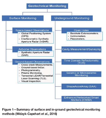
The technologies considered in the evaluation were selected based on their characteristics.
► The in-place inclinometer (IPI) is designed to measure lateral displacement within a borehole. Most commonly, multiple IPIs are installed at varying depths. In this manner, the profile of the displacement can be monitored. The IPI itself consists of one or two (uniaxial or biaxial) MEMS tilt sensors mounted in a stainless steel housing. Each sensor incorporates an onboard microprocessor which performs an automatic temperature compensation of the tilt data. The sensors are powered and the data is read by a logger such as the Campbell Scientific CR1000. Argus software can be used to produce a near real-time profile of displacement that is constantly updated (Machan and Bennett; 2008; Eberhardt and Stead, 2011; Chaulya and Prasad, 2016).
► The vibrating wire piezometer (VWP) is designed to be embedded in soil, rock, fills, and concrete to measure groundwater elevations and water pore pressure when installed in the ground, embankments, concrete structures, pipelines, wells, and other similar structures. VWPs are capable of measuring pore water and fluid pressures in fully or partially saturated soils. More information about VWP technology and its application can be found in a number of works (Applied Geomechanics, 2008; Soil Instruments, 2015; Brawner, 1982; Read et al., 2013; Gillespie, East, and Cobb, 2004; Preene, 2012).
► ShapeAccelArray (SAA) is a sensor that can be placed in a borehole or embedded within a structure to monitor deformation. It consists of a continuum of cable-like segments with embedded triaxial micro-electromechanical system (MEMS) accelerometers. Each segment has a known length. By sensing the gravity field at each segment, the bend angles between each segment can be calculated. Using the calculated bend angles and known segment lengths, the shape of an SAA can be determined. SAAs can be used to determine 3D shape when installed vertically and 2D shape when installed horizontally. 3D shape can be determined when the SAA is installed up to 60 degrees from the zenith. SAAs have a maximum length of 100 m, but several arrays can be installed in a single borehole to cover greater depths. Some drawbacks of this device are that each particular array has a different accuracy due to the nature of the calibration process, gathered data can exhibit significant drift (due to incorrect voltage supply) and, when installed in inclined boreholes, a SAA cannot distinguish torsion from tilting of the array, which can lead to measurement of displacements that do not exist (Swarbrick and Clarke, 2015; Bradley and Prado, 2014; Lipscombe et al., 2014; Dasenbrock, Levesque, and Danisch, 2012).
ENSM technology
The Enhanced Networked Smart Markers (ENSMs) monitoring system is a novel sensing technology being developed specifically to monitor subsurface rock mass deformation and, simultaneously, groundwater pore pressure in open pit mines. The ENSM monitoring system is composed of three main parts: the sensors, an antenna, and the reader station (Figure 2). This technology has the capability of transmitting the data wirelessly between the individual sensors, which has been proven in sensor installations in the field (Widzyk-Capehart et al, 2015).
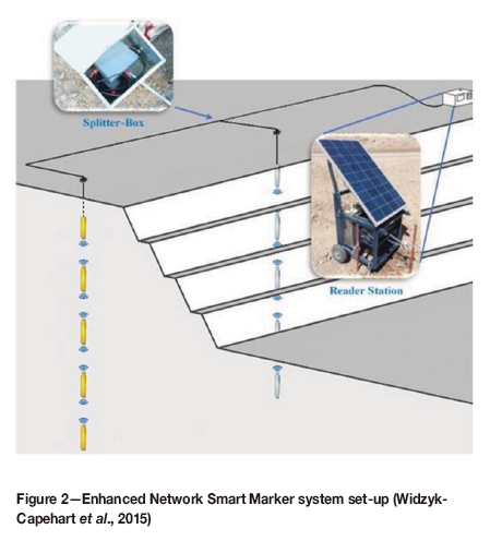
The ENSM has the potential to overcome some limitations of the currently available technologies: savings related to the installation procedure due to the possibility of installing different sensing devices in the same borehole and at the same location (installation point), the elimination of cables and the risk of them being damaged by ground movement, more data from a single hole, and diverse data collocated spatially and temporally in a single hole (Widzyk-Capehart et al., 2016).
This system can be deployed behind a slope wall and can use its wireless communication capabilities to monitor the slope's performance remotely and in near real-time, thus providing mine designers and operators with valuable data towards improving mine operation safety and slope design (Widzyk-Capehart et al., 2016, 2015).
Theoretical mine plan and design
The mine plan for a theoretical copper ore deposit was created using the DeepMine software.
Mine site conditions
The mine plan was developed under the assumption that the open pit mine was constructed in a region with two different rock types. The slope angles in the high-quality (high-strength) rock mass would be steeper than in the poor quality (lower strength) rock mass (Table I).
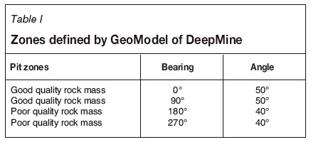
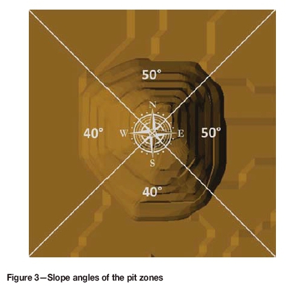
It was assumed that the final pit would have an overall slope angle of 50° in the good quality rock mass area and an angle of 40° in the low quality rock mass (Figure 3). This initial configuration was assumed to be stable along the entire pit perimeter (from a geomechanical perspective).
In addition, the following assumptions were made:
► The rock mass was initially fully saturated, meaning that the water table was located at surface level
► Optimized slope designs include a dewatering campaign
► A single instrumentation borehole could house devices to measure both deformation and pore pressure at the same time and, if required, at the same position
► Detailed mine design was not the main focus of this research: ramps, berms, and other structures inside the pit were not included in the design and the analyses were made considering the outline of the pit only.
Economic and productivity assumptions
The model was built taking into account economic conditions in the copper ore market as of August 2015 and the predictions made by the Central Bank of Chile for the year 2016 (Central Bank of Chile, 2015). A discount rate of 8% was considered for the evaluation and all economic parameters were considered deterministic and invariable for the duration of the mine life.
The mine's maximum annual extraction capacity was set at 40 Mt/a. Five different destinations for the extracted material were defined to allow the DeepMine software to perform coherent mine plan calculations: a concentrator plant, a leaching plant, a sulphide ore stockpile, an oxide and oxide/sulphide transition ore stockpile, and a waste dump.
Open pit project - base case
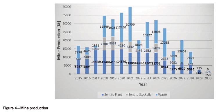
Taking into consideration the mine's extraction rate and processing capacities of both plants, the software simulated a 300 m deep pit with 16 years life-of-mine (LOM), 12 phases (named V1 to V12), and a US$210.51 million net present value (NPV) open pit mining project. The mine plan considered the extraction of 355.03 Mt of material (Figure 4), processing 88.16 Mt of sulphide ore and 95.31 Mt of oxide and oxide/sulphide transition ores. This simulation was defined as the initial scenario (base case) for further sensitivity analysis.
The base case design was optimized by steepening the pit slope to increase the project's NPV. However, an increase in slope angle also increased the risk to operations and the probability of slope failure. Therefore, to mitigate the increase in risk and probability of failure, the mine plan incorporated a slope monitoring campaign as a mean to assess slope performance and future slope stability.
Description of the monitoring campaign
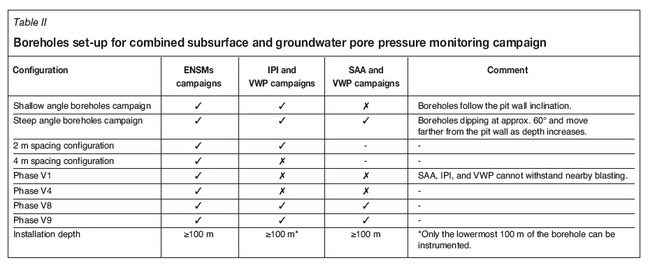
The borehole layout was assumed to be the same for the implementation of each selected technology. However, the inclination of the boreholes varied due to special installation requirements for some of these technologies, which led to two different campaign types (subsurface and groundwater pore pressure campaigns) being required for comparison purposes. The borehole characteristics for each type of campaign and technology are listed in Table II.
With the steepening of the pit slopes, it was necessary to determine in which areas of the open pit slopes stability could have been compromised as a result of the more aggressive design. These areas would be selected for monitoring from the point of view of both safety and profitability. Based on this analysis, the following decisions were made.
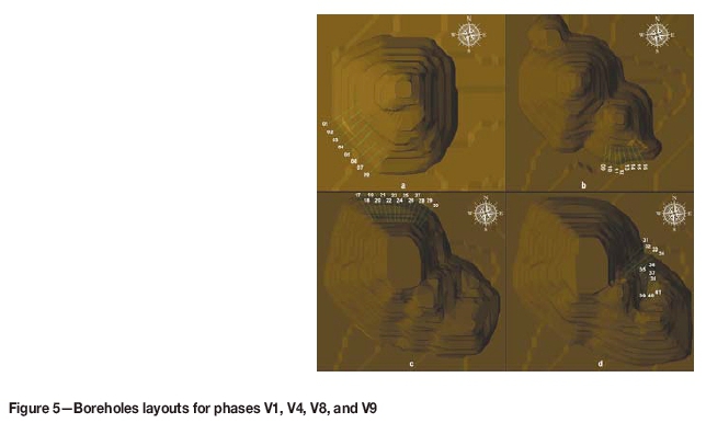
► To assess the initial rock mass conditions, it was decided to instrument the southwestern part of phase V1 (Figure 5a), as phase V1 exposed the first slopes of the mine and enabled the understanding of the initial conditions of the lowest quality rock mass in terms of deformation and ground water presence.
► The southern part of phase V4 (Figure 5b) was to be monitored, as this sector corresponded to one of the shallowest slopes in the pit. Thus, the data acquired from this sector could influence steepening of neighboring phases developed after the extraction of phase V4, such as, phases V5, V6, V9, and/or V10.
► To assess long-term slope stability, phases V8, V9, V10, and V11 should be instrumented and their behaviour monitored, since these phases unveiled the final pit wall. From those alternatives, the northern side of phase V8 was selected as a critical sector (Figure 5c), as it was the first phase to unveil the final pit wall and this portion of the final wall was the longest standing one: nine years from the moment it started to be unveiled and four years from the time it was totally exposed until mine closure (year 2030). Phase V8 also unveiled the steepest side of the pit's final wall, which made it a less conservatively designed pit slope than other areas of the pit.
► Pit walls uncovered by the extraction of phase V4 and phase V9 presented complex convex pit wall geometries, including bullnoses, which are geometries characterized by a stress relaxation due to a lack of confinement and which might create slope stability problems. Thus, to avoid potentially hazardous conditions, both sectors were selected as critical. However, only surface monitoring was advised for the inspection of the bullnoses in phase V4, as they remained in service for less than one year and did not cover the entire depth of the pit at this stage. Conversely, the bullnoses in phase V9 - eastern wall (Figure 5d) remained in service until the end of operations (more than three years) along the entire depth of the final pit. Thus, subsurface deformation monitoring was advised for this critical sector.
Cost of monitoring campaign - comparison and analysis
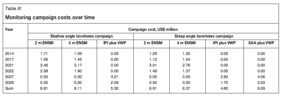
The costs associated with each instrumentation campaign studied in this paper were incorporated into the NPV calculations for all variations in the slope angle. For each alternative (campaign), the cost of: drilling the boreholes, the instruments, and their installation were incorporated in the NPV calculations as variable costs, distributed over time to incorporate the effect of temporality and scheduling for every monitoring campaign installation (Table III).
The shallow angle boreholes campaign considered two alternative technologies: (1) IPI and VWP and (2) ENSM, while the steep angle boreholes campaign considered three instrumentation alternatives: (1) IPI and VWP, (2) SAA coupled with VWP, and (3) ENSM.
From Table III, it can be seen that the IPI plus VWP campaign and SAA plus VWP campaign were the least expensive: US$5.30 million in the shallow angle boreholes campaign; US$4.60 million and US$6.09 million in the steep angle boreholes campaign. However, these two campaigns had to be deployed after the slope to be monitored was completely developed (due to technical limitations of these technologies). Therefore, there were no potential economic benefits rendered by a reduction in waste extraction or an increase in ore recovery when applying those campaigns, since these technologies could only be used to monitor final pit walls.
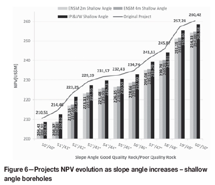
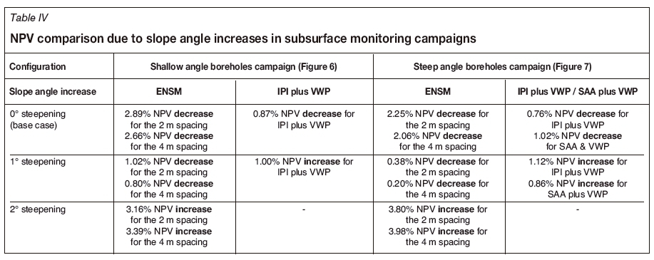
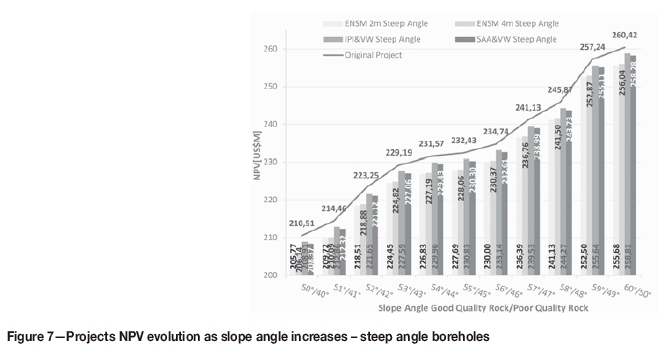
Economic assessments of subsurface monitoring campaigns due to slope angle increases are summarized in Table IV and Figures 6 and 7.
Conclusions
Five subsurface deformation monitoring campaigns were designed with the aim of achieving the highest possible revenue by steepening of slopes while considering subsurface deformation monitoring and the surface monitoring campaigns commonly deployed in the major open pits in the world. These campaigns were designed as an integral part of the mine planning and slope design process. This allowed focusing on the monitoring effort in the most relevant zones for a particular open pit project.
The results obtained clearly show that the proposed campaigns were technically feasible, with ENSMs installation being the most technically advantageous. Moreover, an economical evaluation was undertaken considering the effect of steepening the slope angle by 1° at a time on the instrumented mine project's NPV. This assessment incorporated the potential benefit of a lower waste stripping ratio, which showed the economic viability of all studied alternatives. The campaigns using ENSMs were the most advantageous, in particular, the campaign that considered the installation of one ENSM every 4 m, which presented the lowest cost per unit of gathered data.
A new geotechnical monitoring technology, the Enhanced Networked Smart Markers (ENSM), promises to overcome some drawbacks of the existing technologies by enabling through-the-rock wireless data transmission. The technical feasibility of this wireless data transmission was proven after field testing of these devices in two mine-scale trials for sixteen months.
Acknowledgement
The authors would like to acknowledge the financial support of AMTC through the Chilean Government Conicyt project FB0809 and the Fundaciön CSIRO Chile, under the auspices of CORFO.
References
Applied Geomechanics. 2008. User's manual. Vibrating wire piezometers. http://www.ampere.com.mx/pdf/Manual_Usuario_Bigboy_VWP.pdf [ Links ]
Bank Central of Chile. 2015. Monetary Policy Report. http://www.bcentral.cl [ Links ]
Beale, G., de Souza, J., Smith, R., and St Louis, B. 2013. Implementation of slope depressurisation systems. Guidelines for Evaluating Water in Pit Slope Stability. Beale, G. and Read, J. (eds.). CSIRO Publishing, Collingwood, Victoria. pp. 19-64. [ Links ]
Bradley, B. and Prado, R. 2014. The use of Shape Accel Array for monitoring utilities during urban tunnel drives. Technical Paper, ICE Publishing. [ Links ]
Brawner, C.O. 1982. Control of groundwater in surface mining. International Journal of Mine Water, vol. 1, no. 1. pp. 1-16. [ Links ]
Bye, A.R. and Bell, F.G. 2001. Stability assessment and slope design at Sandsloot open pit. South Africa. International Journal of Rock Mechanics and Mining Sciences, vol. 38, no. 3. pp. 449-466. [ Links ]
Calderon, A.R. and Tapia, A.D. 2006. Slope-steepening decision using a quantified risk assessment: the Chuquicamata case. Proceedings of the 41st US Symposium on Rock Mechanics (USRMS), Golden Rocks, Colorado. Yale, D., Holtz, S., Breeds, C., and Ozbay, U. (eds.). American Rock Mechanics Association, Alexandria, VA. [ Links ]
Cawwod, F.T. and Stacey, T.T. 2006. Survey and geotechnical slope monitoring considerations. Journal of the South African Institute of Mining and Metallurgy, vol. 106. pp. 495-502. [ Links ]
Chaulya, S.K. and Prasad, G.M. 2016. Sensing and Monitoring Technologies for Mines and Hazardous Areas. Monitoring and Prediction technologies, Elsevier. [ Links ]
Dasenbrock, D.D., Levesque, C.L., and Danisch, L. 2012. Long-term behavior monitoring using automated MEMS-based sensing arrays in an urban environment. Landslides and Engineered Slopes: Protecting Society through Improved Understanding. Proceedings of the 11th International and 2nd North American Symposium on Landslides, Banff, Alberta, June 3-8, 2012. Vol. 2. Eberhardt, E.B. (ed.). CRC Press. pp. 1393-1398. [ Links ]
DeepMine. 2015. http://www.boamine.com [accessed January 2015]. [ Links ]
Dunniclif, J. 1998. Geotechnical Instrumentation for Monitoring Field Performance. Wiley, New York. [ Links ]
Dunnicliff, J. 2012. Types of geotechnical instrumentation and their usage. ICE Manual of Geotechnical Engineering, Vol. II. Burland, J., Chapman, T., Skinner, H., and Brown, M. (eds.). Chapter 95: pp. 1379-1403. [ Links ]
Dunnicliff, J., Marr, W.A., and Standing, J. 2012. Principles of geotechnical monitoring. ICE Manual of Geotechnical Engineering, Volume II. Burland, J., Chapman, T., Skinner, H., and Brown, M. (eds,). Chapter 94. pp. 1363-1377. [ Links ]
Eberhardt, E. and Stead, D. 2011. Geotechnical instrumentation. SME Mining Engineering Handbook. Darling, P. (ed.), Society for Mining, Metallurgy, and Exploration, Inc., Littleton, CO. Chapter 8.5. pp. 551-571. [ Links ]
Gillespie, C.D., East, D.R., and Cobb, C.F. 2004. Tailing impoundment permitting, design, construction, and operation in an artic environment. Proceedings of Tailing and Mine Waste 04. Taylor & Francis. London. pp. 27-38. [ Links ]
Hawley, M., Marisett, S., Beale, G., and Stacey, P. 2009. Performance assessment and monitoring. Guidelines for Open Pit Slope Design. Read, J. and Stacey, P. (eds.). CSIRO Publishing, Collingwood, Victoria. Chapter 12. pp. 327-380. [ Links ]
Jefferies, M., Lorig, L., and Alvarez, C. 2008. Influence of rock-strength spatial variability on slope stability. Proceedings of the First International FLAC/DEM Symposium on Numerical Modeling. Hart, R., Detournay, C., and Cundall, P. (eds.). Itasca Consulting Group. Minneapolis, MN. pp. 24-26. [ Links ]
Lipscombe, R., Carter, C., Perkins, O., Thurlow, P., and Guerrero, S. 2014. The use of Shape Accel Arrays (SAA) for measuring retaining wall deflection. Technical Paper, ICE Publishing. [ Links ]
Little, M. 2006. Slope monitoring strategy at Pprust open pit operation. Proceedings of the International Symposium on Stability of Rock Slopes in Open Pit Mining and Civil Engineering. Southern African Institute of Mining and Metallurgy, Johannesburg. pp. 211-230. [ Links ]
Lynch, R.A., and Malovinchko, D.A. 2006. Seismology and slope stability in open pit mines. Proceedings of the International Symposium on Slope Stability in Open Pit Mining and Civil Engineering. Southern African Institute of Mining and Metallurgy, Johannesburg. pp. 375-390. [ Links ]
Machan, G. and Bennett, G.V. 2008. Use of inclinometers for geotechnical instrumentation on transportation projects - State of the practice. Transportation Research Circular, no. E-C129. [ Links ]
Marr, W.A. 2013. Instrumentation and monitoring of slope stability. Proceedings of Geo-Congress 2013: Stability and Performance of Slopes and Embankments III. Pando, M.A., Pradel, D., Meehan, C., and Labuz, J.F. (eds.). pp. 2231-2252. [ Links ]
Mphathiwa, N. and Cawood, F.T. 2014. Design principles for optimizing an established survey slope monitoring system. Journal of the Southern African Institute of Mining and Metallurgy, vol. 114, no. 6. pp. 463-470. [ Links ]
Preene, M. 2012. Groundwater control. ICE Manual of Geotechnical Engineering, vol. II. Burland, J., Chapman, T., Skinner, H., and Brown, M. (eds.). ICE Publishing. pp. 1173-1190. [ Links ]
Read, J., Beale, G., Ruest, M., and Robotham, M. 2013. Guidelines for Evaluating Water in Pit Slope Stability. Beale, G.and. Read, J. (eds.). CSIRO Publishing, Collingwood, Victoria. pp. 1-18. [ Links ]
Soil Instruments. 2015. Standard vibrating wire piezometer. user manual. http://www.itmsoilsupport.com/manuals/Man106_Standard_Vibrating_Wire_Piezometer.pdf [ Links ]
Sperling, T., Freeze, R.A., Massmann, J., Smith, L., and James, B. 1992. Hydrogeological Decision Analysis: 3. Application to Design of a Ground-Water Control System at an Open Pit Mine. Ground Water, vol. 30, no. 3. pp. 376-389. [ Links ]
Stacey, P. 2009. Fundamentals of slope design. Guidelines for Open Pit Slope Design. Read, J. and Stacey, P. (eds.). CSIRO Publishing, Collingwood, Victoria. pp. 1-14. [ Links ]
Stacey, T.R. and Xianbin, Y. 2004. "Extension" in large open pit slopes and possible consequences. Proceedings of the 4th International Conference and Exhibition on Mass Mining, Santiago Chile 22-25 August 2004. Alfaro, M.A. and Karzulovic, A. (eds). Mineria Chilena, pp. 280-285. [ Links ]
Stacey, T.R., Xianbin, Y., Armstrong, R., and Keyter, G.J. 2003. New slope stability considerations for deep open pit mines. Journal of the South African Institute of Mining and Metallurgy, vol. 103, no. 6. pp. 373-389. [ Links ]
Steffen, O.K.H., Contreras, L.F., Terbrugge, P.J., and Venter, J. 2008. A risk evaluation approach for pit slope design. Proceedings of the 42nd US Symposium on Rock Mechanics (USRMS). American Rock Mechanics Association, Alexandria, VA. https://pdfs.semanticscholar.org/a8edZ44d00bde85797911064ab8fa3fce99350748.pdf [ Links ]
Swarbrick, G.E. and Clarke, S.J. 2015. Shape Accel Arrays - Comparative performance in a mining application. Proceedings of the Ninth International Symposium on Field Measurements in Geomechanics. Australian Centre for Geomechanics, Perth. pp. 195-206. [ Links ]
Widzyk-Capehart, E., Hölck, C., Fredes, O., Pedemonte, I., and Steffen, S. 2015. Implementation of novel subsurface deformation sensing device for open pit slope stability monitoring - The Networked Smart Markers System. Proceedings of the 23rd International Symposium on Mine Planning and Equipment Selection (MPES 2015). Southern African Institute of Mining and Metallurgy, Johannesburg. pp. 203-214. [ Links ]
Widzyk-Capehart, E., Hölck, C., Fredes, O., Rivero, V., Snachez, E., Pedemonte, I., Gonzalez, N., and Steffen, S. 2016. Understanding rock mass behaviour through the development of an intergrated sensing platform. Proceedings of the Seventh International Conference and Exhibition on Mass Mining, Sydney. Australasian Institute of Mining and Metallurgy, Melbourne. pp. 275-284. [ Links ] ♦
Paper received Aug. 2017
Revised paper received Jul. 2018

