


Services on Demand
Article
 English (pdf)
 Article in xml format
 Article references
Indicators

Related links
-
 Cited by Google
 -
 Similars in Google
Share

 Permalink
Journal of the Southern African Institute of Mining and Metallurgy
On-line version ISSN 2411-9717
Print version ISSN 2225-6253
J. S. Afr. Inst. Min. Metall. vol.118 n.11 Johannesburg Nov. 2018
http://dx.doi.org/10.17159/2411-9717/2018/v118n11a11
PAPERS OF GENERAL INTEREST
Silicomanganese production at Mogale Alloys
N.A. SitholeI; N. RambudaII; J.D. SteenkampI; D.A. HaymanI; C. HockadayI
IMintek, Johannesburg, South Africa
IIMogale Alloys, Krugersdorp, South Africa
SYNOPSIS
Mogale Alloys operates two alternating current (AC) submerged arc furnaces (SAFs), and two direct current (DC) open bath furnaces. These furnaces are capable of producing two products, silicomanganese (SiMn) and ferrochrome (FeCr), with a total production capacity of 110 000 t/a. This paper focuses on the silicomanganese process specific to Mogale Alloys, with a two-furnace operation facility that produces 55 000 t of SiMn per annum.
Keywords: silicomanganese, submerged arc furnace, Mogale Alloys.
Introduction
Mogale Alloys is situated in Krugersdorp in the West Rand District Municipality in South Africa's Gauteng Province. The Krugersdorp facilities were initiated by Palmiet Chrome Corporation in February 1963 to produce charge chrome (Basson, Curr, and Gericke, 2007). Mogale Alloys bought the Palmiet Chrome facilities in 2005 from Samancor Chrome. The Afarak Group currently owns 90% of Mogale Alloys.
SiMn is produced in two 20 MVA submerged arc furnaces (SAFs), which were originally built for chromite processing, and ferrochromium (FeCr) in two DC open bath furnaces rated at 40 MVA and 10 MVA. When this paper was compiled, the 10 MVA furnace was not operational due to the high cost of production, and one of the 20 MVA SAFs was recently converted to produce FeCr due to market constraints. Mogale Alloys has 290 permanent employees with four contracting companies on site. The paper presented here focuses on the production of SiMn at Mogale Alloys.
The high-level process flow at Mogale Alloys is summarized in Figure 1, which details the raw material input and the products produced by the two 20 MVA furnaces. SiMn is produced by carbothermic reduction of manganese-bearing raw materials from four different sources, namely Wessels, Mamatwan, and UMK ores, and BHP sinter feed. The carbon sources are bituminous coal from Forzando and Msobo, local suppliers in Mpumalanga.
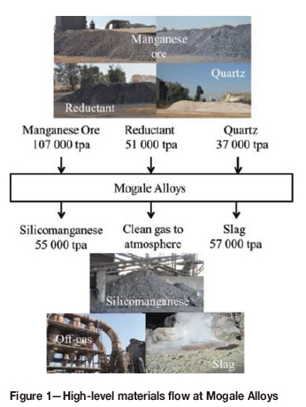
Figure 2 depicts the location of raw material suppliers relative to Mogale Alloys.
Quartz is sourced from South African producers located in Marble Hall in Limpopo.
The SiMn is primarily produced for the export market. Slag is disposed of off-site. Offgas is vented to the atmosphere after cleaning.
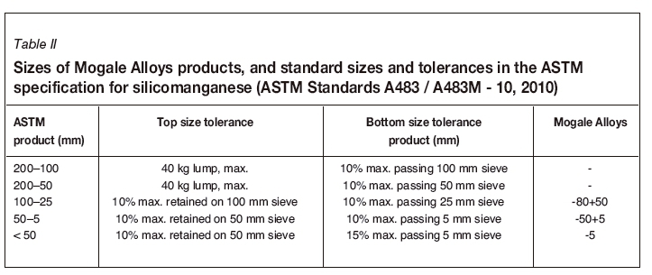
The chemical composition of the SiMn produced at Mogale Alloys is typical of ASTM grade B (ASTM Standards A483/A483M - 10, 2010) shown in Table I. The product size ranges, in comparison with the ASTM specifications, are summarized in Table II. Three product sizes are produced, the two larger size fractions being sold and the smaller fraction used to line the casting beds.

Process description
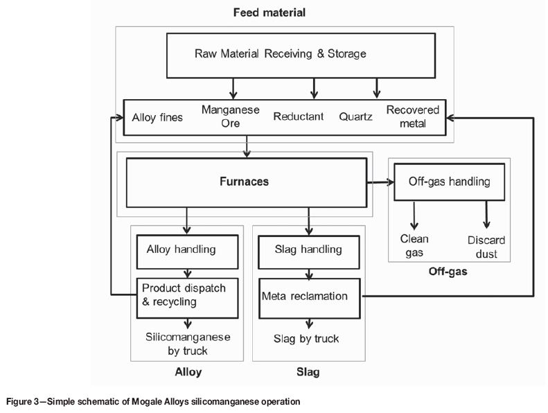
A basic schematic of the operations at Mogale Alloys is provided in Figure 3.
Feed material
Raw materials
The feed to the furnaces comprises a blend of the various ores and quartz as listed in Table III. The compositions of these raw materials have a large influence on the product composition. Therefore, the recipe is adjusted to produce SiMn containing 65% Mn, 17% Si, 14% Fe, and a maximum of 2% C with an 80% metal recovery. The quartz provides silicon to the metal and also fluxes the slag system.
Most of the manganese ores (Wessels, Mamatwan, UMK, and BHP sinter) are sourced from the Hotazel area in the Northern Cape Province (Figure 2). The selection of the different types of ore is governed by the manganese content, ratio of manganese to iron (Mn/Fe), reducibility, price, and carbonate content. To manage the risk of non- or delayed delivery, different suppliers are used to allow for a constant supply of raw materials. The various factors are optimized to reduce production costs and meet product specifications. From Table III it can be seen that the manganese contents of the ores and sinter are fairly similar, but that the iron content varies significantly, as indicated by the Mn/Fe ratios. Another variable is the carbonate content of the ore. The problem with carbonate-rich ores, seen in Table III with low manganese-to-carbonate ratios, is that they consume large amounts of fixed carbon, and increase the partial pressure of carbon monoxide (PCO) in the system because of the Boudouard reaction, shown in Equation [1] (Olsen, Tangstad, and Lindstad, 2007). This reaction typically proceeds at temperatures exceeding 800°C.

Therefore, the Mamatwan and UMK ores are maintained at less than 65% of the feed ore. Wessels ore contains less carbonate material than the other two ores, but is the highest contributor towards the iron content in the process. Wessels ore is more cost-effective than the BHP sinter and Mamatwan ore. Although both the manganese-bearing ores and the reductants contain silicon, the primary source of silicon in the blend is quartz, with the typical composition indicated in Table III. The addition of quartz is required for the silicon content in SiMn, but the system is fluxed by the SiO2. The slag basicity B3 is adjusted by the quartz according to Equation [2] (Olsen, Tangstad, and Lindstad, 2007).

The carbon required for the reduction of manganese and silicon is provided by bituminous coal. Bituminous coal is less costly than anthracite, and more readily available in South Africa (Wellbeloved and Kemink, 1995). However, technical difficulties arise as a result of the high volatile matter content, which causes a phenol build-up in the effluent from the wet scrubbers (Wellbeloved and Kemink, 1995).
Manganese-containing feed material is a combination of raw ore, sinter, and recycled by-products of the process such as alloy fines and metal-rich slag. The alloy fines have the same composition as the tapped metal product (Table I). The composition of the metal-rich slag is not analysed.
Furnace feed system
The flow of raw materials, from delivery by truck to feeding into the furnace, is summarized schematically in Figure 4.
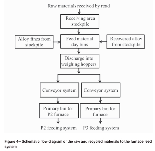
The raw materials are delivered by suppliers and are placed in stockpiles in the receiving yard. The material from the stockpiles is transported by trucks and discharged into hoppers that store the raw material in day bins. From the day bins, the raw materials are released into weighing hoppers where the feed is mixed. The conveyor system then transports the mixed feed into the primary bins. Two separate primary bins are used for furnaces P2 and P3. Feeding is done manually using the two vehicles shown in Figure 5.
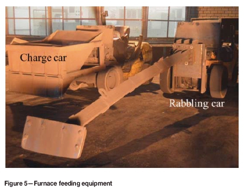
The contents of the primary bin are poured into the charge car and the feed material is discharged inside the furnace through the opening. The rabbling cars then come in and push the material closer to the electrodes.
Furnaces
Mass and energy balance
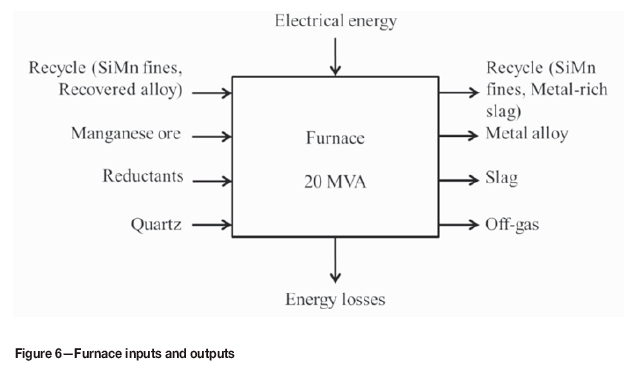
Figure 6 depicts a schematic flow diagram of one of the furnaces. The feed rates of the input and output material are presented Table V. The data is for furnace 3, based on a single 3100 kg batch of feed material. The furnaces are operated at the same capacity and are controlled to yield the same amount of metal with minimal amounts of slag in the output. This will result in an average slag-to-metal ratio of 1.05 for furnace 3.


Furnace layout
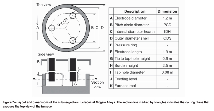
The 20 MVA furnaces at Mogale Alloys are capable of switching between SiMn and FeCr production (Basson, Curr, and Gericke, 2007). FeCr processes require higher temperatures than SiMn, around 1800°C, and higher resistances to reach these temperatures. Coke is used for FeCr production and the slag to metal ratio is higher. These furnaces are semi-open SAFs operated with three Söderberg electrodes positioned in equilateral arrangement. Various modifications have been made to the furnaces over the years as ownership changed. The furnaces are identical in dimensions, and both furnace facilities were modified in 2010 to change the electrode diameter from 1 m to 1.2 m before the Afarak group bought the facilities.
From a theoretical perspective, an increase in electrode diameter at the same conductivity increases its current carrying capacity (Dougall and Gasik, 2013). Figure 7 and Table VI present the dimensions of the current furnace layout.
Table VI lists the design power rating (PR), operating power (OP), electrode diameter (ED), electrode pitch circle diameter (PCD), PCD power intensity (PITpcd), outer diameter of steel shell (ODS), internal diameter of hearth refractory (IDH), and hearth power intensity (PIThearth). The electrode PCD power intensity is related to the operating power and the PCD, according to Equation [3].

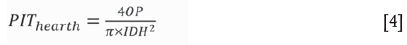
The hearth power intensity (PIThearth) is related to the operating power (OP) and the internal diameter of hearth refractory (IDH), according to Equation [4].
The layout in Figure 7 and parameters tabulated in Table VI all work together to transform electrical energy to meet the energy requirements of the reactions and heating of products. In order to produce SiMn, heat transfer is required to facilitate the temperature-dependent reactions. The furnace burden height H is significantly higher than the electrode tip where the arc forms, hence the furnace burden covers the electrodes and the arc, which is why the furnaces are termed 'submerged-arc'. However, the bulk of the energy transferred is through ohmic (resistance) heating due to the short arc (Saevarsdottir and Gasik, 2013). Ohmic heating requires the current to flow through a medium that resists (electrical resistance) current flow in order to produce heat. In the SiMn furnace the slag is the resistant medium where the heat is generated (Saevarsdottir and Gasik, 2013). The transformer power rating is related to the production capacity - enough power must be available to meet the company's yearly production targets (Saevarsdottir and Gasik, 2013). This power value is estimated the from mass and energy balance of the process (Saevarsdottir and Gasik, 2013). Parameters of the furnace bath are then considered along with the required electrode resistance and current (Saevarsdottir and Gasik, 2013), because the electrodes are the means of transferring power from the transformer to the process materials. The furnace freeboard is the gap between the furnace roof K and the top of the burden H. It is designed according to the amount of gas and dust generated by the process. Therefore a high gas volume generation will require a large combustion chamber.
Electrode management
The purpose of an electrode is to deliver the current to the slag. Multiple calculations are carried out to derive parameters such as the electrode current, voltage, and diameter (Gasik, 2013). The electrodes are selected to meet current demands using their maximum current-carrying capacity, which is determined by the electrode material and diameter. The maximum current-carrying capacity of an electrode is the upper limit of the furnace operating current, which should be greater than the full load current. An optimal selection of current density also minimizes arcing. Arcing is an indication of an unbaked electrode at the pressure ring and contact pads, since the steel casing can only handle a 25 kA current. The PCD is used to distribute the heat evenly across the furnace hearth, since the electrodes create hotspots. A smaller PCD causes the electrode hotspots to be in close proximity, which increases the process temperature at the centre of the furnace. At Mogale Alloys the SiMn furnaces are designed such that one electrode is in line with the tap-hole in order to minimize metal freezing during tapping.
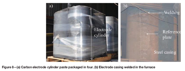
Söderberg self-baking electrodes require careful control to ensure that the operation runs as expected. This due to the softening and baking that electrode paste undergoes before it can adequately carry current to the correct location in the furnace. Softening and baking are dictated by the temperature profile in the electrode column (Nelson and Prins, 2004). Self-baking electrodes are prepared by welding cylindrical casings and inserting the electrode paste cylinders as shown in Figure 8a. During normal operation, the electrode cylinder paste melts in the casing at the top and starts baking at temperatures around 450-500°C further down the shaft. Above these temperatures, even further down the shaft, the electrode solidifies, forming graphite, and becomes electrically conductive. The steel casings (Figure 8b) then melt and are incorporated into the charge mix. Self-baking electrodes are preferred since they are cheaper, and require less preparation than prebaked electrodes, despite the fact prebaked electrodes have a superior current-carrying capacity (Jones, 2014). This is due to the size limitation on prebaked electrodes; once they exceed 700 mm in diameter they become very costly and difficult to source (Reynolds and Jones, 2005).
For effecting control, various factors need to be taken into account, such as the electrode submerged length, electrode paste additions, baking zone, hard and soft paste levels, slipping rate, and temperature profile (Nelson and Prins, 2004). The estimated length of the electrode submerged into the burden is obtained manually, by allowing the furnace to melt out for a period of 8 hours, with no feeding, until the electrode tips are uncovered. A rope is then dropped from the top of the electrode, just under the pressure ring, until it reaches the electrode tip. The measurements are then taken and used to determine the slip length. Electrode slipping is done hourly, and monitoring of the electrode is done by the foreman on every shift, which lasts for 8 hours. Operating the furnace with short electrodes will result in an increased coal demand in the charge, while operating with long electrodes will require less coal in the feed charge. Both scenarios will cause the alloy grade to be poor, hence good electrode management is required.
Figure 9 is a schematic drawing of the Söderberg electrode set-up in a submerged arc furnace. The top and bottom pressure rings are used to hold the electrode in place, and the bottom ring contains the contact shoe, through which the current is supplied to the electrode. The jacks can be either pneumatic or hydraulic, and are used for electrode clamping and slipping. The solid and liquid level measurements are used to determine the number of electrode paste cylinders to be added to maintain the liquid level in the appropriate range. Electrode paste additions are used to calculate electrode consumption ratios. Figure 10 shows a schematic drawing of the electrode casings that have been welded together, the solid cylinder, and molten paste.
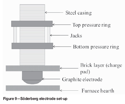

The solid level is measured by dropping a tape, which has a metal weight at the end, inside the steel casing so that it touches the top part of the unmelted cylindrical electrode. The liquid level is then measured by dropping the tape into the gap between the fins of the casing and solid electrode cylinder to obtain the distance between the molten paste and the top of the steel casing. High or low liquid levels will cause the electrode to break, hence monitoring is important to reduce the downtime associated with electrode breakage. 'Green break' is the term used to describe what happens when liquid starts to leak from the casing due to over-slipping and the electrodes are not allowed to bake properly. To prevent green breaking, the liquid paste level measurements, together with the furnace control system, are used to ensure proper baking and slipping in furnaces P2 and P3.
Furnace control
Furnace control is achieved using the FurnStar Minstral submerged-arc furnace control system, which employs a resistance algorithm patented by Mintek (Mintek, 2011). In summary, the system uses resistance values to achieve its control objectives. Resistance values can be set to between 0.9 and 1.2 mQ, with the transformer size determining the power intensity of the furnace. There are two control variables that are used, current and resistance (Mulholland, Brereton-Stiles, and Hockaday, 2009). Current-based control is simple, familiar, and yields the same results as resistance-based control when furnace conditions are stable (Mulholland, Brereton-Stiles, and Hockaday, 2009). However, resistance-based control is deemed better in unsteady furnaces, because it decouples the electrodes and does not move unaffected electrodes due to resultant interactions (Mulholland, Brereton-Stiles, and Hockaday, 2009).
At Mogale Alloys the primary current is used as a reference controlling parameter since it can limit the power input, unlike transformer capacity or electrode diameter (Barker, 1980).
Production data
The mass balance data in Table V was used to calculate various efficiencies (given in Table VII). The carbon efficiencies were calculated using the mass percentage of fixed carbon (Table IV) multiplied by the mass of reductant (Table V). Table VIII lists the compositions of the tapped metal and slag obtained by the efficiencies shown in Table VII.

The aim of production is to meet the metal product specifications and the required capacity while keeping production costs low. This can be seen by the low slag-tometal ratio that is close to unity in Table VII and the low standard deviation values in Table VIII.
The slag-to-metal ratio is low enough to meet product specifications without energy being wasted on extra waste material. The average MnO content in Table VIII is within the expected 10-20% loss for the discard slag process (Gasik, 2013). There are no excessive losses of MnO to the slag that characterize a system with too much slag (Olsen and Tangstad, 2004). The availability of the both furnaces is high, and production is carried out year-round with minimal downtime. The standard deviation for most of the constituents is low, except for MnO and CaO in the slag. Due to the nature of the operations, there is a time delay between receiving production information and changing the feed material. For a cost-efficient process, MnO in the slag must be kept low, but the deviations arise when the recipe changes, which causes the furnace to receive more MnO than can be reduced by the available reductant.
Furnace tapping
The furnaces are tapped every 2 hours. Each furnace is tapped from a single, single-level tap-hole, with the metal and slag both being tapped from the same tap-hole. Tap-holes are drilled open, using drill-and-mud-gun technology. Tap-holes are lanced open only when difficulties with drilling are experienced, i.e. when the metal/slag is frozen in the tapping channel. The metal and slag flow along a 1 m long launder into a refractory-lined ladle, seen in Figure 11a. Due its higher density, the metal settles at the bottom of the ladle, and slag overflows into a slag pot (see Figure 11a). The slag that remains on top of the metal is skimmed off into the metal-rich slag bay, by letting the slag trickle out of the ladle (see Figure 11b). Lastly, the metal is poured onto a launder that skims more slag while guiding the metal into the casting pit (see Figure 11c).
Burden control
The SAFs at Mogale Alloys are semi-open to the atmosphere, with half of the open area covered using three furnace covers placed in an equilateral formation (Figure 12). The furnace roof is completely separated from the furnace shell by a 1.5 m gap and the gaps between the furnace covers are utilized for charging, rabbling, and also for visual inspection of the burden (Figure 12). The burden level must at all times be just above the furnace seal and level throughout. To ensure this, the burden is rabbled conducted on a regular basis to achieve two main objectives: levelling of the burden, and improving burden permeability. Levelling is needed to minimize heat losses, as well as losses of Mn and SiO vapour and fines. Ensuring burden permeability is important to avoid furnace blowouts, which occur primarily as a result of the flow of gases through the burden being hindered.
Other causes of furnaces blowout include high slag levels in the furnace, electrode position, a large amount of fines, and poor slag basicity control resulting in a viscous slag.
Alloy
The metal is cast onto casting beds lined with SiMn fines, as indicated in Figure 13b. The SiMn fines are also used as an embankment around the casting pits to contain the liquid alloy. Alloy from both furnace ladles is cast in one casting bed. It is then allowed to cool and solidify (Figure 13a) before being excavated and moved by front-end loader to the crushing plant, while the next casting bed is used. As a layer of alloy is allowed to solidify before the next layer is cast onto it, the layers remain separate. As a result, when the material is removed, the alloy breaks easily into pieces. The front-end loader moves the alloy from the casting bed to the alloy stockpile (Figure 13c).
The stockpiled material is fed to the alloy processing plant, where it is crushed and screened into different product sizes. The process flow sheet for the alloy processing plant is given in Figure 14. The stockpiled alloy from the casting beds is fed into the primary jaw crusher and then to a grizzly screen. The +80 mm oversized fraction is reduced in the secondary jaw crusher and returned to the grizzly screen. The -80 mm undersized fraction is fed to a multi-deck screen, which produces -80+50 mm, -50+5 mm, and -5 mm fractions. The 80+50 mm and -50+5 mm products are stored in bunkers. The -5 mm fines, which are not saleable, are stockpiled for use on the casting beds and for remelting.
Slag
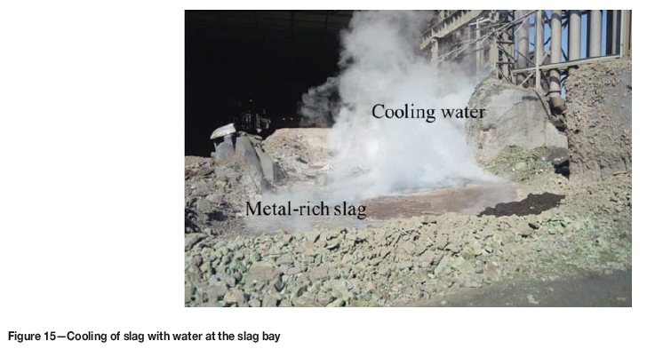
After tapping the product, the ladle is taken to the slag area, where the slag is skimmed off. The slag is cooled using water as indicated in Figure 15.
Around 20% of the metal is entrained in the slag. This is a significant amount, and recovery of the metal is required. Metal recovery is done off-site by a contractor. Figure 16 details the material flow diagram of the slag handling plant.
The stockpiled slag is transported from Mogale Alloys by truck to the slag processing plant. The material is fed into a jaw crusher where it is reduced to -18 mm, then the metallic lumps are hand-picked. The metal is taken to the metal product stockpile. Once the remaining slag has accumulated to 60 t it is fed into a vibrating screen where the metallic product is recovered into the +8 mm fraction, which goes to the product stockpile. The -8 mm product is fed into a jig, which recovers a further10-15% of the metallic product.
Off-gas
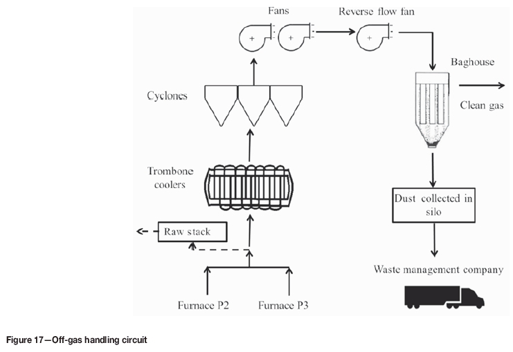
Each furnace has three off-gas removal ducts, one above each electrode, which lead into a single duct. The ducts from the two furnaces join before the off-gas is treated (see Figure 17). The off-gas bypasses the raw-gas stack and goes into trombone coolers where heat is exchanged with the atmosphere. Large particles are removed using pre-collector cyclones. The smaller particles flow to the bag filter plant through the action of a reverse flow fan. The dust recovered from the baghouse is stored in a silo for collection by a waste management company and disposal off-site.
Conclusions
As one of only two producers of SiMn in South Africa, Mogale Alloys has been producing silicomanganese since 2005. Due to market constraints, SiMn production was reduced by 50% in 2016, by converting one of the two 20 MVA SAFs at Mogale Alloys to FeCr production.
As plans are underway to convert the second SAF to FeCr production, the information presented here captures useful details of SiMn production at Mogale Alloys.
Acknowledgements
This paper is published with the permission of Mintek and Mogale Alloys.
References
ASTM Standards A483 / A483M - 10, 2010. Standard Specification for Silicomanganese. ASTM International, West Conshohocken, PA. [ Links ]
Barker, I.J. 1980. An electrode controller for submerged arc furnaces. IFAC Proceedings, vol. 13, no. 7. pp. 611-621. [ Links ]
Basson, J., Curr, T.R., and Gericke, W.A., 2007. South Africa's ferro alloys industry - present status and future outlook. Innovations in Ferro Alloy industry. Proceedings of INFACON XI, New Delhi, India, 18-21 February 2007. Indian Ferro Alloy Producers Association. pp. 3-24. [ Links ]
Dougall, I.M. and Gasik, M. 2013. Ferroalloys processing equipment. Handbook of Ferroalloys. Elsevier. pp. 83-138. [ Links ]
Gasik, M. 2013. Handbook of Ferroalloys: Theory and Technology. Butterworth-Heinemann, uK. [ Links ]
Jones, R.T. 2014. DC arc furnaces - past, present, and future. Celebrating the Megascale: Proceedings of the Extraction and Processing Division. Symposium on Pyrometallurgy in Honor of David G.C. Robertson. Mackey P.J., Grimsey E.J., Jones R.T., and Brooks G.A. (eds.). The Minerals, Metals & Materials Society, Warrendale, PA. pp. 129-139. [ Links ]
Mintek. 2011. Measurement and control solutions. http://www.mintek.co.za/technical-divisions/measurement-and-control-solutions-mac/control-solutions/furnstar/ [accessed 7 June 2018]. [ Links ]
Mulholland, A., Brereton-Stiles, P., and Hockaday, C. 2009. The effectiveness of current control of submerged arc furnace electrode penetration in selected scenarios. Journal of the Southern African Institute of Mining and Metallurgy, vol. 109. pp. 601-607. [ Links ]
Nelson, L.R. and Prins, F.X. 2004. Insights into the influences of paste additions and levels on Söderberg electrode management. Proceedings of INFACONX: Transformation through Technology, Cape Town, South Africa, 1-4 February 2004. Southern African Institute of Mining and Metallurgy, Johannesburg. pp. 418-431. https://www.pyrometallurgy.co.za/InfaconX/045.pdf [ Links ]
Olsen E, Tangstad, M., and Lindstad, T. 2007. Production of manganese ferroalloys. Tapir Academic Press, Trondheim, Norway. [ Links ]
Olsen, S.E. and Tangstad, M. 2004. Silicomanganese production - process understanding. Proceedings of INFACON X: Transformation throughTechnology, Cape Town, South Africa. Southern African Institute of Mining and Metallurgy, Johannesburg. pp. 231-238. [ Links ]
Reynolds, Q.G. and Jones, R.T. 2006. Twin-electrode DC smelting furnaces - Theory and photographic testwork. Minerals Engineering, vol. 19, no. 3. pp. 325-333. [ Links ]
Saevarsdottir, G. and Gasik, M. 2013. Electric and thermal operations of furnaces for ferroalloys production. Handbook of Ferroalloys. Elsevier. pp. 139-175. [ Links ]
Wellbeloved, D.B. and Kemink, M., 1995. The economic and technical implications of the use of coal rather than coke as a reductant at Metalloys. Proceedings of the 7th International Ferroalloys Congress (INFACON VII), Trondheim, Norway. Tveit, H., Tuset, J.K., and Page, I.G. (eds). Norwegian Ferroalloy Producers Research Organization (FFF). pp. 191-199. [ Links ]
Wikimedia Foundation, Inc. Not dated. Provinces of South Africa. https://en.wikipedia.org/wiki/Provinces_of_South_Africa#/media/File:Map_of_So uth_Africa_with_provincial_borders.svg [accessed 7 June 2018]. [ Links ] ♦

