


Services on Demand
Article
 English (pdf)
 Article in xml format
 Article references
Indicators

Related links
-
 Cited by Google
 -
 Similars in Google
Share

 Permalink
Journal of the Southern African Institute of Mining and Metallurgy
On-line version ISSN 2411-9717
Print version ISSN 2225-6253
J. S. Afr. Inst. Min. Metall. vol.118 n.11 Johannesburg Nov. 2018
http://dx.doi.org/10.17159/2411-9717/2018/v118n11a6
COPPER COBALT AFRICA
Innovative process design for copper-cobalt oxide ores in the Democratic Republic of Congo
D. AlexanderI; C. van der MerweII; R. LumbuleII; J. KgomoII
IERG Africa, South Africa
IIBoss Mining, Democratic Republic of Congo
SYNOPSIS
The mining industry in the Democratic Republic of Congo has seen a significant expansion in copper and cobalt production in recent years. The greater proportion of this expansion has arisen through processing of oxide ores. The design of metallurgical processes for these oxide ores is based on the conventional equipment and layout for processing of sulphide ores, and comprises milling followed by leaching, solvent extraction, and electrowinning. The physical characteristics of the oxide ores, however, provide the process design engineer with an opportunity to examine critically the principles on which equipment selection is based and to design processes better suited to these ores. In 2015, ERG Africa began a project to expand the leaching capacity of the Luita hydrometallurgical facility. A number of innovative changes to the conventional process design were included in the modified flow sheet, which were validated when the project reached design throughput in November 2017. Of these changes, the most novel presented an alternative approach to mitigate the impact of colloidal silica on the operation of the solvent extraction plant.
Keywords: copper, cobalt, process design, oxide ores, solvent extraction, colloidal silica management.
Introduction
ERG Africa operates the Luita hydrometallurgical facility located at Kakanda in the Democratic Republic of Congo (DRC), treating malachite and heterogenite minerals to recover copper as electrowon cathode and cobalt as a hydroxide precipitate. The process was originally conceived as a heap leach operation followed by direct electrowinning of copper, with solvent extraction (SX) and electrowinning (EW) of cobalt. In preparing the sized ore for the heap leach operations, the undersized ore fraction at a P80 of 625 um was discharged to a fines storage facility for later processing. This fraction carried with it approximately 30% of the copper contained in the run-of-mine (ROM) ore feed, and an equivalent proportion of cobalt.
In a subsequent development, the cobalt SX section was converted to a copper SX facility, the leached cobalt being recovered from a bleed stream from the copper heap leach circuit. The operating cost for the process as then installed placed this facility well in the fourth quartile of the industry cost curve.
The initial Luita operation was established in 2010 at a time when metal prices were above long-term averages (copper above US$3.00 per pound; cobalt above US$20.00 per pound), and the drop in prices in 2015/2016 presented a major challenge. The London Metal Exchange (LME) copper price dropped below US$2.00 per pound, with cobalt dropping below US$10.00 per pound in Q1 2016. This set in motion a range of improvement initiatives for the Luita operation. Central to this was the installation of a tank leach circuit to process the discarded fines and a modified SX circuit to manage colloidal silica. The revised Luita circuit reached design capacity in November 2017 and has proven to be well suited to processing of the oxide ore feed. This process design challenges the boundaries of conventional thinking in the areas of leaching, solid/liquid separation, solution management, impurity management, and metal recovery, and is the subject of this paper.
Process description (2015)
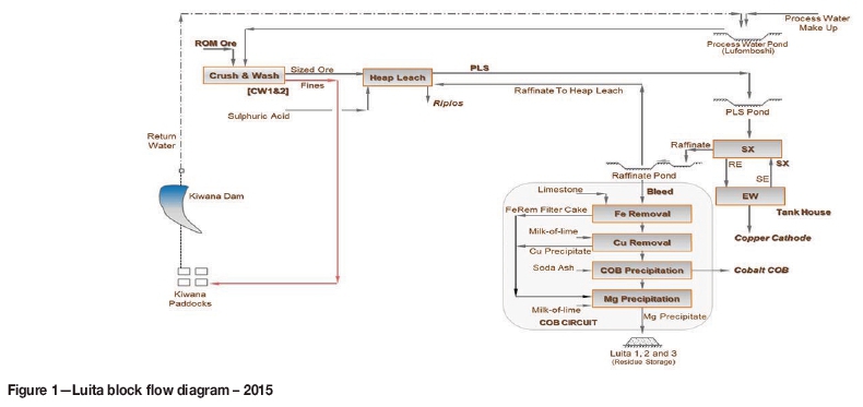
The Luita plant block flow diagram as it was in 2015 is illustrated in Figure 1. ROM ore was processed through two crushing and washing plants to produce a sized ore (-50 mm +625 um) for the heap leach operation. The undersized ore (-625 um 'fines') was removed from the feed in order to allow for a maximum heap irrigation rate of 90 L/m2/h. The selected irrigation rate took advantage of the rapid leaching kinetics of malachite.
The pregnant leach solution (PLS) recovered from the heaps was clarified and then processed through SX and EW circuits to produce the copper cathode product. The cobalt was recovered from a raffinate bleed stream by iron and copper precipitation processes, followed by precipitation of a basic cobalt hydroxide sulphate by-product utilizing soda ash as a precipitant.
Opportunities
In developing the process design for the uprated Luita circuit, the following areas were assessed.
(i) Overall solution management: Conventional process designs will seek to limit addition of water to the process through equipment and technology selection, and provide for a neutralization process to manage excess solution build-up. Little use is made of natural water removal processes such as evaporation.
(ii) Optimum particle size for leaching: A reduction in particle top size is often required to liberate the targeted minerals for effective leaching. Major operations in the DRC specify a P80 from 75 um to 200 um for the leach feed, and milling becomes the default technology selection. For the copper oxide ores, effective liberation may be achieved at a much coarser particle top size, bringing into question technologies selected for the size reduction duty.
(iii) Silica management: Colloidal silica in the PLS presents processing challenges for the operation of many SX circuits. Much attention has been placed on flocculation/coagulation measures applied upstream as a means of containing, rather than controlling, the effects of colloidal silica formation. The management of colloidal silica within the SX circuit itself has not been extensively explored.
(iv) Layout of the copper tankhouse: With no successful strategy defined for management of silica, tankhouses are being designed such that the rich electrolyte from the SX plant, passes first through a bank of electrolytic cells (referred to as scavenger cells) to capture the organic phase entrained in the electrolyte. Copper cathodes produced from these cells are typically downgraded on quality grounds.
Process design changes
Taking into consideration these processing issues, an alternative process design was developed around a tank leach operation for processing the fines then being discarded. Key process design changes and the impact on the overall process are described in the following sections.
Solution management
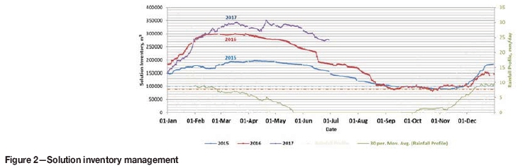
In the Luita heap leach operation, the working solution inventory is between 90 000 m3 and 100 000 m3, and provision was made in the original design for a spillage inventory capacity of a further 100 000 m3. However, this did not take into account the 200 000 m3 of rainfall per season on the heap leach footprint. This resulted in 100 000 m3 of excess solution being processed through the neutralization circuit each season to prevent process ponds from overflowing. The impact of rainfall addition on the total inventory movement through 2015, 2016, and into 2017 is illustrated in Figure 2.
Data past June 2017 has been excluded. The commissioning of the tank leach circuit introduced an additional water supply into the process, requiring a change to the solution management philosophy to manage the additional volume. The increase in Q1 2017 over 2016 reflects the impact of the tank leach.
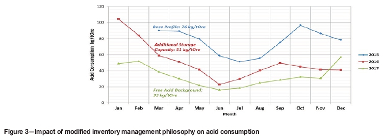
In a typical annual cycle, the inventory will peak in February/March and reach a minimum in November. Taking into consideration water deficiency at the height of the dry season (September to October), the decision was taken to expand the solution storage capacity of the Luita spillage circuit by a further 150 000 m3 to capture rainfall during the wet season and to optimize evaporation profiles through the balance of the year through the heap spray irrigation system. The direct impact of the revised inventory management philosophy was a reduction in consumption of neutralizing reagents and a more effective utilization of sulphuric acid in the process. Further optimization of process conditions (dropping the free acid background in the raffinate leach solution to below 30 g/L) has reduced acid consumption by half over the period 2015 to 2017, as illustrated in Figure 3.
Leach design
The oxide ROM ores are composed of dolomite, dolomitic shales, and argillites. The primary ore minerals present are malachite [CuCO3.Cu(OH)2] and heterogenite [CoO(OH)]. The chief components of the orebodies impacting on process design are silica, talc, and dolomite.
For comparative purposes, images of malachite and chalcopyrite samples from the Kakanda ore complexes are included in Figure 4, illustrating key differences in mineralization. Malachite has a massive mode of occurrence, while chalcopyrite is crystalline and disseminated in the host rock.
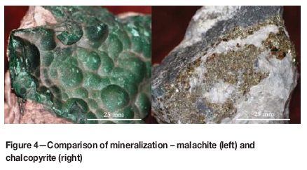
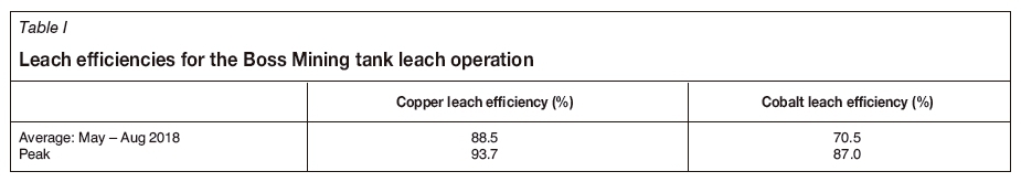
In a fundamental change in thinking around process design, when opting to process the undersize ore from the crushing circuit, the decision was taken to exclude further size reduction technologies (milling) from the process; in effect, to leach the crusher fines through a tank leach facility at a P80of 625 um (well above the industry norm). Key considerations in arriving at this decision were the massive nature of the malachite (Figure 4) and the risk of elevated gangue acid consumption when gangue constituents (specifically dolomite) are ground to finer product sizes. Metallurgical test work indicated a potential saving in gangue acid consumption of over 20 kg/t ore when leaching at a P80 of 625 um as opposed to leaching at a P80of 150 um. No benefit in copper leaching was evident in leaching at the finer particle size. The tank leach was then designed for a three-hour residence time, focusing primarily on copper recovery -lower cobalt recoveries were indicated in early test work; however, particle size distribution was identified as only one of a number of variables affecting leach efficiency, along with residence time and iron concentration in solution. From the economic assessments carried out, it was determined that the reduced operating costs associated with the acid savings outweighed the potential loss in revenue from lower cobalt recoveries. Since commissioning, the success achieved in optimizing the cobalt leach efficiency to values above that indicated in the bench-scale test work has justified the decision to design the leach circuit for processing of the crusher fines.
The leach efficiencies subsequently achieved through the tank leach operation are summarized in Table I. The average leach efficiencies for the four months May to August 2018 represent the tank leach circuit having reached nameplate capacity.
Processing of ores with particle top sizes greater than 200 um brings into question the selection and design of equipment typically found in a base metal hydrometallurgical circuit. Dewatering cyclones prove to be ineffective on broad particle size distributions, and thickener designs typically cater for slow-settling solids milled finer than 400 um. Taking such factors into consideration, the design philosophy adopted for the Luita circuit was to focus on movement of the coarser size fraction through the tank leach section. The leach tanks were designed as overflow tanks with full homogenous suspension of particles at a P100 of 1000 um, with sufficient power installed to re-suspend the load following a dead stop (for example, following a power trip). In conventional circuit design, continuous withdrawal of slurry from the bottom of each leach tank at a volumetric flow rate equivalent to up to 20% of the feed flow rate is included in order to move forward heavier particles that do not readily suspend. Such a cropping system was excluded from the Luita tank leach design; an alternative proprietary system was installed to bleed forward a smaller volume of slurry on a batch basis, only when an increase in the slurry density at the bottom of the tank is detected. In this way, a 'true' overflow leach train is installed (as opposed to the 'dual transfer' system when making use of cropping pumps).
Given the free-settling nature of the coarser particles, horizontal vacuum belt filters were selected for solid-liquid separation, as opposed to countercurrent decantation (CCD). This offered the opportunity to reduce wash water volumes (lower the wash ratio) for fast-settling solids and to size a smaller processing circuit for metals recovery from the low-grade filter cake wash solution.
Silica management: solvent extraction circuit design
One of the biggest challenges facing hydrometallurgical operations in the DRC lies in managing silica leached from siliceous minerals such as chrysocolla [Cu2H2Si2O5(OH)4]. As per conventional design, the Luita facility includes a bleed stream to remove impurities from the circulating PLS; cobalt is then recovered from the bleed stream as a hydroxide precipitate. Referring to the solution inventory profiles illustrated in Figure 2, background impurity concentrations in the solution inventory are at their lowest in the first quarter of the year, when dilution from rainwater ingress reaches a maximum. Through the year (April to October), the solution inventory is then managed down and this results in a corresponding increase in the concentration of impurities reporting to the bleed stream and exiting the process. This impurity management system is effective for all impurities other than silica,.
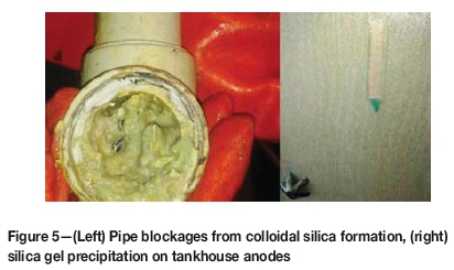
As the solution inventory reduces through the year (primarily through evaporation) the increasing silica concentration reaches a series of tipping points where massive colloidal silica formation in the Luita process solutions occurs almost overnight. The consequence of this is massive aqueous and organic entrainment through the SX circuit into the EW tankhouse. This is driven by colloidal silica crud formation, as the silica finds an alternative exit from the circulating process solutions in the leach circuit. In the tankhouse, the silica and organic phases disengage, 'silica sand' being collected from the floors of the EW cells and the organic phase floated off the surface of the electrolyte. The consequence of this silica deportment mechanism is organic staining on the copper cathodes and consequent downgrading of the product. Typically, this occurs every two to three months through the dry season and presents a significant disruption to the SX/EW processes.
The effects of the colloidal silica formation are illustrated in Figure 5. Pipe blockages and fouling of in-line instruments both in the leach circuits and in the tankhouse are common, and silica precipitation on the anodes in the tankhouse has been associated with marked reductions in current efficiency. During such excursions, current efficiencies as low as 50% have been reported.
Work carried out on the use of coagulants to control silica in leach process solutions raises concern over the effect on the downstream SX operation, with at least one operation in the DRC in the recent past experiencing significant process disruptions following a trial run utilizing coagulants.
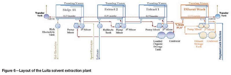
In reviewing the operation of the Luita facility, a key observation during silica excursions was that the crud formed in the SX was of a low density and non-compacting. The crud sat at the interface in the extract settlers, reporting with the organic phase to the strip circuit and then with the aqueous phase into the tankhouse. Recognizing the potential to manage the silica deportment by forcing the formation of a higher density, compacting crud, a novel approach to the design of the SX circuit was adopted, providing for a diluent wash section at the front of the process. The layout of the Luita SX circuit is illustrated in Figure 6, highlighting the positioning of the diluent wash section.
In operation, an unclarified PLS is contacted with the diluent containing no extractant in the diluent wash section. The function of the diluent wash is to form a compacting crud that will encapsulate the low-density silica crud, thus rendering it more manageable through crud removal processes and subsequent tricanter centrifuge operation. The 'clean' PLS is then fed forward to the first extraction stage of the conventional SX circuit.
Pilot plant campaign
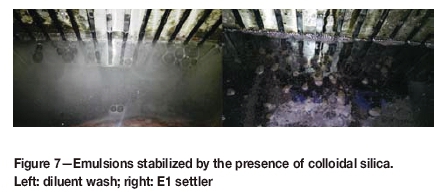
The proposed SX circuit was piloted to highlight the process issues being encountered in managing silica, and to develop operating parameters for the commercial installation. The issues pertaining to colloidal silica formation are illustrated in Figure 7, where the colloidal silica is seen to stabilize the emulsion exiting the picket fence in the diluent wash settler and in the E1 extract settler.
The nature of the crud formed from the colloidal silica is illustrated in Figure 8.
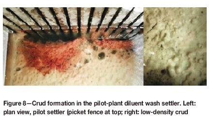
The darker crud phase, closer to the picket fence in Figure 8, shows the formation of the more compact, higher density crud being targeted. Aqueous entrainment in the non-compacting low-density crud phase is highlighted.
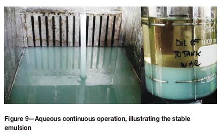
In the past Luita operation, 'phase flipping' at organic flow rates lower than 1.5 times the aqueous flow rates (internal O:A ratio lower than 1.5) was a common occurrence and the SX circuit was operated at O:A ratios greater than 2.0 to force organic continuity through all stages of the operation. When operating under aqueous-continuous conditions (O:A less than 1.0), settling times extended beyond 10 minutes (compared with 2 minutes in organic-continuous mode) and entrainment increased significantly. The effect of operating in aqueous continuity on phase disengagement times is illustrated in Figure 9 in the pilot settler unit and a laboratory flask (photograph taken after 10 minutes' settling time). Formation of the stable emulsion is evident.
Commercial operation
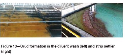
The new Luita SX installation was commissioned in July 2017 with commercially available diluent and extractant products. Within two weeks, the circuit was operating at design transfer capacity. As is common practice, the circuit start-up was with diluent and the value of the novel operating philosophy was immediately apparent. In addition to the diluent wash, crud formation in the strip settlers highlighted the 'dirty' nature of the EW electrolyte, contaminated by entrainment from the operation of the older, decommissioned, SX circuit. The crud formation in the diluent wash and strip settlers during commissioning is illustrated in Figure 10.
In the new SX circuit, no clarification of the PLS is carried out, the solids loading assisting with the crud management in the diluent wash. The diluent wash itself serves as an effective clarification unit with the solids concentration in the PLS entering the first extract stage being reduced to below 20 mg/L.
An unanticipated benefit of the diluent wash lies in the fact that the diluent is transparent. This makes it simpler to manage the crud formation in the diluent wash circuit as opposed to the extraction and stripping sections, where the mixing of extractant into the diluent generates an opaque organic phase (refer to Figures 7 and 11).
Colloidal silica in solution is notably difficult to analyse because of the propensity to form under varying conditions of pH and total silica concentration. While the benefit that the diluent wash section brings to the Luita circuit has been difficult to quantify solely through analytical measurements of silica in solution (reported silica assays typically ranging between 500 mg/L and 1000 mg/L), improvements noted include the following.
(i) Whereas the older SX could not operate in aqueous-continuous mode, the new installation is operated at the desired continuity for any particular extraction or stripping stage. The E1 stage is now operated successfully in aqueous-continuity mode (O:A ratio less than 1.0).
(ii) Both extractant and diluent consumption have reduced. The full extent of the reduction is still being evaluated, but to date, reductions of 75% and 65%, respectively, are indicated.
(iii) In line with the reduction in organic consumption, aqueous entrainment to the tankhouse has reduced significantly and this is discussed in following sections.
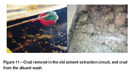
The overall improvement in the Luita operation may best be characterized by comparison of the crud removal mechanism used in the old SX circuit and the nature of the crud now being generated from the new installation (Figure 11).
In the old SX circuit, crud removal proved to be a significant challenge with much of the crud draining through the makeshift sieves 'manufactured' for this purpose. Following commissioning of the diluent wash circuit, crud is removed effectively through a modern vacuum system, and a compact crud is discharged from the tricanter units.
Tankhouse design
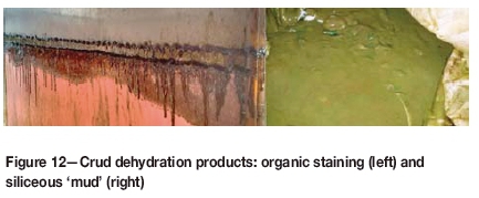
The following mechanism explains the deportment of silica to the EW tankhouse (Parris, 2009). Colloidal silica combines with the organic phase in the SX circuit to form a stable low-density crud that contains a high proportion of the aqueous phase within its structure. This crud tracks with the lower density organic phase through SX, through the strip stage and into the rich electrolyte. In the more acidic rich electrolyte, the colloidal silica separates from the organic phase, and this is evidenced by organic floating on the surface of the electrolyte in the EW cells, staining the copper cathodes, and siliceous mud recovered from the base of the EW cells during the cleaning cycles. Parris describes further the ongoing, unordered coalescing of the colloidal silica in the low pH environment, in the extreme case generating the silica gel illustrated in Figure 5 on the anodes and the siliceous mud removed from the floor of the EW cells. Examples of organic staining from a South American operation and siliceous mud collected form the Luita EW cells are illustrated in Figure 12.
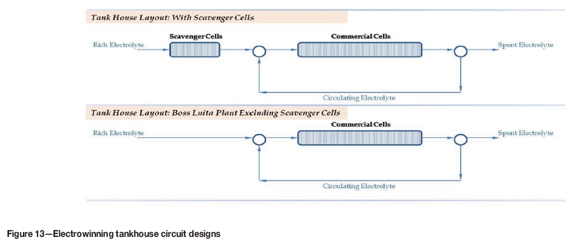
In response to the process issues relating to formation of colloidal silica and aqueous entrainment into the tankhouse, current tankhouse designs provide for a 'scavenger section' at the front end of the tankhouse. The operating philosophy for the scavenger cells is to allow for the disengagement of the entrained organic phase contained in the 'dirty' rich electrolyte, and for the disengaged organic phase to be 'burnt off (evaporated). The 'clean' rich electrolyte may then be sent forward to the commercial section of the tankhouse, where the primary copper cathode product is plated. It is noted that the disengagement, or 'dehydration', process in the scavenger cells (and subsequent evaporation of the organic phase) has a strong time-dependency, influencing the number of cells assigned to the 'scavenger' duty Key shortcomings in this process design concept are:
(i) There is no direct control over the disengagement of the entrained organic and organic 'burning off process. In practice, where there may be some loss of the diluent fraction through evaporation the entrained organic disengaged from the rich electrolyte (primarily the extractant) is physically removed from the cells along with the copper cathodes (organic staining).
(ii) The downgrading of the copper cathode product plated in the scavenger cells. In current designs this may be anything from 10% to 30% of the overall copper production.
(iii) Holding an organic phase on the electrolyte surface of operating electrowinning cells presents a significant hazard. Studies into the ignition of fires in solvent extraction plants have identified two contributing factors, namely:
a. Formation of a vapour phase
b. Potential for a spark source
Both of these factors are present in the design concept for the scavenger cells.
The success of the Luita SX circuit design and diluent wash in addressing the organic entrainment issue has resulted in a significant improvement in the quality of the rich electrolyte reporting to the copper tankhouse and, as a direct consequence of this, the chemical and physical qualities of the copper cathodes produced. As a result, the design of the Luita EW tankhouse was modified to remove scavenger cells from the layout; this change in EW circuit design is illustrated in Figure 13.
The benefits attributed to the novel design concepts introduced into the Luita plant operation are best illustrated by the improvements in two key aspects of the copper electrowinning operation:
► Cell cleaning: reduction in the mass of silica mud recovered from the EW cells
► Copper cathode quality: reduction in impurities (Fe, S, and Pb).
Cell cleaning
Prior to the introduction of the new SX circuit and diluent wash, the EW cells in the Luita tankhouse were cleaned on a 25-day cycle; this required cleaning of 12 cells per day. For each cell to be cleaned, the rectifier amperage is reduced to allow for short-circuiting bars to be installed, and following cleaning the rectifier amperage is reduced again to remove the shorting bars and bring the cleaned cell back on line. The mass of siliceous mud removed through the cleaning cycle averaged 252 kg per day (see Table II).
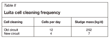
Following commissioning of the diluent wash circuit, the cell cleaning cycle has been extended to 75 days (four cells cleaned per day), with the mass of siliceous mud removed reduced to an average of 7 kg per day. The cell cleaning schedule is still below the industry norm of 120 to 180 days, but this represents an area for further improvement.
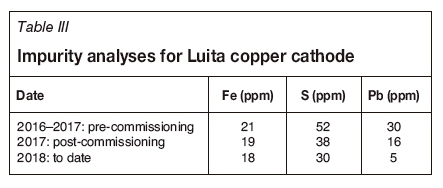
Copper cathode quality
In the Boss Luita tankhouse operation, key impurities tracked are iron, sulphur, and lead. Trends in these analyses, following commissioning of the tank leach circuit and diluent wash in July 2017 are illustrated in Figure 14.
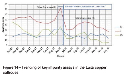
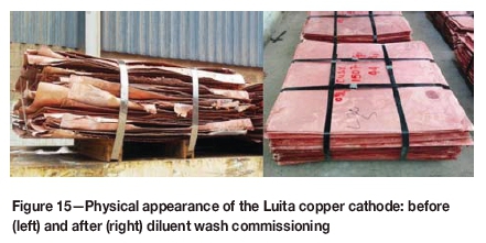
Immediately prior to the commissioning of the new SX circuit a silica excursion (massive colloidal silica formation) was experienced, and this is highlighted as Silica Excursion (1) in Figure 14. The spike in sulphur assay at this time is also evident. A further excursion occurred three months later. The impact of this excursion (Silica Excursion (2) in Figure 14) was less severe with the diluent wash in circuit and provided Boss with an opportunity to refine the operating parameters for the diluent wash. Since then the operation has seen a steady improvement in both the physical and chemical quality of the copper cathode product. The improvement in is summarized in Table III and illustrated in Figure 15.
Process description (2018)
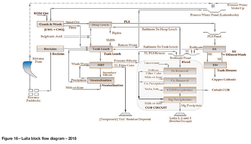
The Luita plant process flow as it is in 2018 is illustrated in Figure 16.
Further process design changes have seen the copper precipitation process in the cobalt recovery (COB) circuit replaced by a SX circuit, improving the chemical quality of the cobalt COB product.
Conclusions
In 2015, ERG Africa initiated a project at the Boss Mining Luita process plant to provide for tank leaching of a crusher fines discard product and to uprate the SX plant capacity. The novelty in these two initiatives lay in the proposals to leach the crusher fines at a coarse particle size distribution (P80 of 625 um), and to provide for a diluent wash section at the front end of the SX circuit to manage the impact of colloidal silica formation on the downstream EW process. The project reached nameplate capacity in November 2017, and the novelty introduced into the process design has contributed to significant reductions in consumption of key reagents including sulphuric acid, diluent, and extractant, with minimal loss in leaching efficiency for copper and cobalt. Introduction of the diluent wash into the SX circuit has provided a means to manage the deportment of silica through the process, specifically to the copper tankhouse, and this has resulted in a marked improvement in the chemical and physical characteristics of the copper cathode produced.
Following a retrospective review of this and other projects in the DRC, further opportunities have been identified aimed at improving the overall efficiency in future process designs for processing of DRC oxide ores.
Acknowledgements
Acknowledgement is given to ERG Management, not only for permission to present this paper, but also for creating an environment where innovation and exploitation of considered risk opportunities is supported.
The involvement of specific vendors and reagent suppliers in bench and piloting test work before and after project initiation, and in critically assessing the proposed design concepts, is also acknowledged.
► BASF: SX pilot plant
► Solvay: SX pilot plant
► Outotec: solid suspension and abrasion test work; Sand Sense/Sand Gate technology for density control in the leach tanks
► Roytec: filtration and flocculation test work (horizontal belt filters)
► Kemira: flocculation test work (horizontal belt filters)
► ProProcess: CRUD FORX for crud removal from SX settlers.
References
Auchterlonie, A. and Lydall, M.I. 2011. The Democratic Republic of Congo and Zambia: A growing global 'hotspot' for copper cobalt mineral investment and exploitation. Proceedings of the 6th Southern Africa Base Metals Conference 2011, Phalaborwa, 18-21 July. Southern African Institute of Mining and Metallurgy. Johannesburg. pp. 25-38. [ Links ]
Robinson, T.G., Sole, K.C., Sandoval, S., Moats, M.S., Siegmund, A., and Davenport, W.G. 2013. Copper electrowinning: 2013 world tankhouse operating data. Proceedings of Copper-Cobre 2013, Santiago, Chile. Vol. V. Gecamin. Santiago. pp. 3-14. [ Links ]
Fisher, K.G. 2011. Cobalt processing developments. Proceedings of the 6th Southern Africa Base Metals Conference 2011, Phalaborwa, 18-21 July. Southern African Institute of Mining and Metallurgy. Johannesburg. pp. 237-258. [ Links ]
Goel, N., Luzanga, A., Sandoval, S., and Tshifungat, O. 2015. Improvements in copper electrowinning at Tenke Fungurume Mining Company. Proceedings of the Copper Cobalt Africa Conference, victoria Falls, Livingstone, Zambia, 6-8 July. Southern African Institute of Mining and Metallurgy Johannesburg. pp. 497-502. [ Links ]
PARRIS, D. 2009. Silica in acid leaching. Parris Consulting Limited, Parkville, Victoria, Australia. [ Links ]

