


Services on Demand
Article
 English (pdf)
 Article in xml format
 Article references
Indicators

Related links
-
 Cited by Google
 -
 Similars in Google
Share

 Permalink
Journal of the Southern African Institute of Mining and Metallurgy
On-line version ISSN 2411-9717
Print version ISSN 2225-6253
J. S. Afr. Inst. Min. Metall. vol.118 n.10 Johannesburg Oct. 2018
http://dx.doi.org/10.17159/2411-9717/2018/v118n10a9
Fully mechanized longwall mining with two shearers: A case study
Y. YuanI; H. LiuI; S. TuI; H. WeiI; Z. ChenI; M. JiaII
IKey Laboratory of Deep Coal Resource Mining, Ministry of Education of China, School of Mines, State Key Laboratory of Coal Resources and Safe Mining, China University of Mining and Technology, China
IIYancon Group Company Limited, China
SYNOPSIS
To reduce production costs and increase efficiency in ageing coal mines, a system that utilizes two shearers in a fully mechanized longwall working face is proposed. Using theoretical and engineering experience, three issues pertaining to the system were determined: (a) the two-shearer mining technique; (b) matching and modifying the equipment; (c) and coal-cutting task allocation for each shearer. Two mining processes are proposed, with the two shearers travelling in either the same or opposing directions. To avoid breakage of chains and pan extrusion of the armoured face conveyor (AFC), the length of the AFC 'snake' was controlled. To ensure continuous cutting and transporting of coal, the cross-sectional dimensions of the AFC were checked and the shearer closer to the head drive was modified. Based on the assumption of equal cutting times for each shearer, the meeting position of the two shearers was obtained by using a theoretical model of mining task allocation. Application of this technique at No. 2 Jining Mine, China, has shown remarkable benefits: daily production capacity was increased by 54% and personnel efficiency was improved by 33 t/d per person.
Keywords: super-long working face, two shearers, AFC.'snake' length, shearer modification, coal-cutting task allocation.
Introduction
All coal mines aim to increase the unit output of the working face to reduce mining costs and improve the economic efficiency of the operation. To achieve this goal, a production model known as one miningface of the mining area has been adopted by most Chinese coal mines (Hu, Meng, and Zhu, 2008; Zhang, Zhang, and Wang, 2000). Under these conditions, the main technical approaches to maximize the output are increasing the width of the working face (Qu, Xu, and Xue, 2009) and accelerating the advancing speed (Robbins, 2000). In coalfields with shallow seams, the width of a fully mechanized face exceeds 300 m (Ju and Zhu, 2015; Fu, Song, and Xing, 2010); in coalfields with deep seams, the width of the face is usually greater than 240 m (Liu et al., 2016; Li et al., 2013). The term 'super-long working face' was proposed to describe working faces with a width of over 240 m (Zhao and Song, 2016; Xu et al, 2007) in China. To support these long working faces with rapid advancing speeds, high-powered mining equipment is required (Kulshreshtha and Parikh, 2001, 2002; Tu et al., 2009; Mishra, Sugla,and Singha, 2013). This is easily achieved in newly built mines, but is not a good choice for ageing mines because of the low return on a high investment on account of the limited remaining resources. It is therefore difficult for ageing mines to significantly increase their unit output with the existing mining equipment. This study focused on this problem: two shearers were applied to a longwall fully mechanized working face (LFMWF) to achieve increased unit output.
It is easy to understand that longwall fully mechanized mining with two shearers (LFMMTS) can increase the unit output by accelerating the advancing speed; however, this also exacerbates the difficulty of matching mining equipment and the risks of production accidents. Jurecka (1987) proposed that it was reasonable to use two shearers in cases with tectonic faulting and for cutting roadways. Bolilasi (1985), using numerical simulation, proposed that the advancing speed can be increased by 55 m/d by adding mining equipment. Niu (2009) theoretically determined that the efficiency can be increased by 600 t/h by using two shearers in a 400 m wide longwall face. Zhang et al. (2009) proposed and proved the feasibility of a concept named 'longwall coal miningface with a multi coal shearers combined mining technology'. Wu and Zhang (2012) and Ceng et al. (2016) showed that using LFMMTS increased the output and advancing speed of the LFMWF 11502 at Yushujing Mine, China.
All previous studies showed that the application of two shearers can increase the output and efficiency of a working face; however, use of LFMMTS also exacerbates the difficulty of matching mining equipment, for example if the capacity of the AFC does not match the total capacity of the two shearers. There are also risks of production accidents, such as the rupture of chains and compression of the AFC when workers push the AFC to the coal wall and head-on collisions of two shearers travelling in opposite directions, as there will be one more AFC 'snake'.
Based on the current mining equipment in LFMWF 9303 in No. 2 Jining Mine, China, the mining process, equipment matching and modification, and coal-cutting task allocations for each shearer were studied. It was shown that LFMMTS can achieve safe and high-efficiency production. This case study can provide a reference for a new technical scheme for safe and efficient mining in coal seams with similar conditions.
Geological condition of LFMWF 9303, Jining Mine
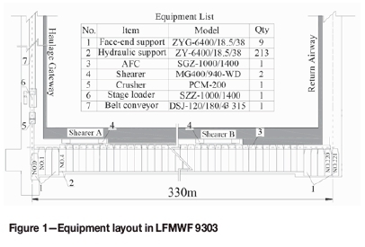
LFMWF 9303 is 1624.6 m long and 330 m wide across the gateroad centre. The coal seam dip ranges from 0° to 12° and is 5° on average. The seam thickness is 2.68 m. The main roof is interbedded medium- and fine-grained sandstone with an average thickness of 37.1 m; the friable immediate roof is siltstone with an average thickness of 0.43 m; the immediate floor is siltstone with an average thickness of 1.91 m; the main floor is medium-grained sandstone with an average thickness of 16.2 m. The geological parameters of the surrounding rock of LFMWF9303 are shown in Table I.
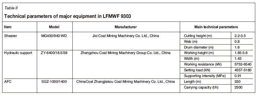
Equipment selection for an LFMWF should take into account geological and mining conditions, capacity and size matching of equipment, and coal yield of the face (Alvarez et al, 2003; Torano et al, 2008). Based on the coal face parameters and these principles, the technical parameters of the major equipment in LFMWF 9303 are summarized in Table II. The equipment layout of two-shearer fully mechanized working face (TSFMWF) is shown in Figure 1.
Techniques using TSFMWF mining
The TSFMWF technique can be classified according to whether the two shearers travel in the same direction or in the opposite directions, as shown in Figure 2.
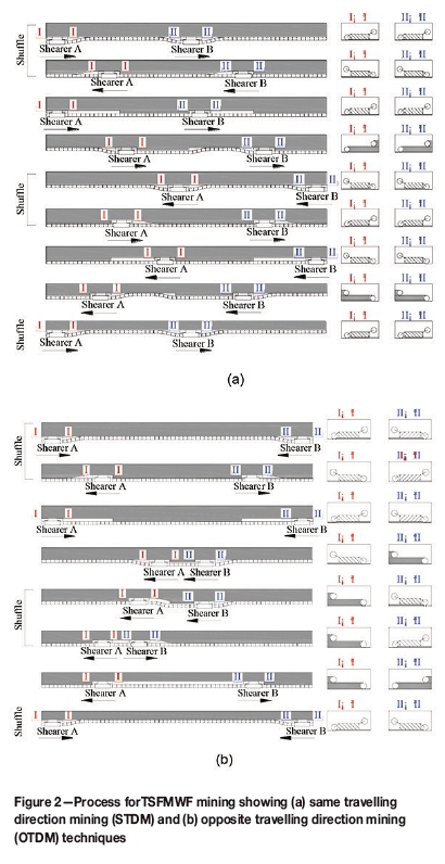
In the same travelling direction mining (STDM) technique, shown in Figure 2a, shearer A travels from the head drive to the middle of the working face and shearer B travels from the middle of the working face to the tail drive. The two shearers cut into the coal wall with an inclined shuffle and a certain distance is required for completing the shuffle. After the inclined shuffle, the AFC is pushed straight. The two shearers then return to their initial positions along the AFC to cut the triangular area by exchanging the positions of the leading and trailing drums. Shearers A and B then start to cut coal regularly towards the tail drive, until they complete the cutting cycle. After one cutting cycle, each shearer returns to its initial position via the same process, but towards the head drive.
In the opposite travelling direction mining (OTDM) technique, shown in Figure 2b, shearers A and B travel from the head drive and tail drive, respectively, to the middle of working face. They first cut into the coal wall with an inclined shuffle, after which the AFC is pushed. A certain distance is required to complete the inclined shuffle. Shearers A and B then return to cut the remaining triangular area. After that process, the two shearers start to cut coal regularly towards each other, until they reach the shared coal-cutting area. In this technique, the two shearers meet in the middle of the face, after which shearer A will have an inclined shuffle and then return to the head drive with regular cutting, while shearer B will cut the coal wall between the two shearers and the triangular area left by shearer A, and then return to the tail drive with regular cutting.
AFC constraints and modification of shearer A
The requirements for the AFC and shearers in LFMMTS differ from those in LFMWF with a single shearer. The AFC should be checked to avoid rupture of its chains or compression of its pans. Shearer A should be modified to meet the demands of coal transportation.
Requirements for AFC
Control of 'snake' length: When using the OTDM technique, the chains may be broken and pans squeezed when workers push the AFC to the coal wall during mid-face operations. It is therefore necessary to determine the reasonable 'snake' length of the AFC.
Checking of cross-sectional dimensions: In productive practice, the carrying capacity of the AFC must exceed the total cutting capacity of two shearers. It is necessary to check that the cross-sectional dimensions of coal piled on the AFC are adequate to accommodate the coal cut by the two shearers.
Requirements for shearerA
► Slipper height-Massive coal is transported by an AFC in LFMMTS, which needs a higher clearance between shearer A and the AFC. The slippers of shearer A must be heightened to enlarge this clearance.
► Drum diameter-Once the slippers are heightened, the drum diameter of shearer A should be increased appropriately to cut the coal at the bottom of coal wall.
Procedure to check constraints of AFC
Determination of the minimum 'snake' length
The minimum 'snake' length (MSL) of the AFC is a very important parameter for safe and high-efficiency mining. Two problems can occur if the actual snake length is less than the MSL: difficulty in pushing the AFC can increase because the pans are prone to be abraded, and there is an increased risk of the chains breaking if the tensions between two chains of the AFC are unbalanced.
Considering the symmetry of the bending section, a theoretical model (Edwards, 1981; Edwards and Yazdi, 1983) for a half-bending section was established, as shown in Figure 3, where N is the number of pans in the half-bending section, ß is the included angle between two pans, bwis the chord length corresponding to ß, L is the length of a pan and a is the width, W is the length of 'snake; S is the width. B is the distance that the AFC is moved at each turn, and AS is the infinitesimal flexion of a bending section for chain number N.
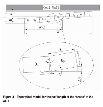
Considering the geometrical relationship of those parameters shown in Figure 3, an expression for AS can be given as:
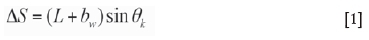
By integration:
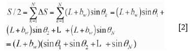
where 0N is the included angle between pan N and the longitudinal line of the AFC (e1 = 1Д 02= 20, 0N = Nß) and bwis the chord length that corresponds to ß (bw= aß /360). Equation [2] can be rewritten as follows:
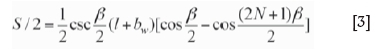
In production practice, B = S - a, so this equation becomes:
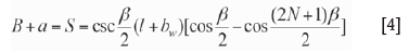
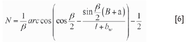
Equation [4] can be simplified to an expression for N:
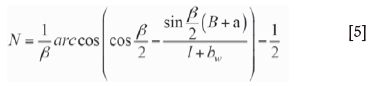
The AFC used in LFMWF 9303 is a SGZ1000/1400 model (ChinaCoal Zhangiakou Coal Mining Machinery Co. Ltd., China) whose pan is 1500 mm long and 1000 mm wide. Their angle of rotation is 1°. The distance that the AFC is pushed at each turn is 800 mm. N is related to B, ß, and a. The values of N for different values of B, ß, and a are shown in Figure 4.
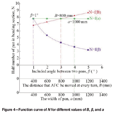
In Figure 4, the values of N are 7.79, 7.80, and 7.80 when the values of a, ß, and B are 1000 mm, 1°, and 800 mm, respectively. Therefore, the maximum value of Nis equal to 7.80 and W = 2NZ = 23.4 m. When using the OTDM technique, a safe distance between two shearers is required to avoid accidents: this should be greater than the MSL. In production practice, a safe distance of 30 m is adopted, known as the shared coal-cutting area. As shown in Figure 2b, the two shearers will be conducting different mining processes when they reach the shared coal-cutting area.
Cross-sectional dimension checking for coal piled on the AFC
According to the number and type of spill plates installed on the AFC, the method for calculating the cross-sectional dimensions of coal conveyed by the AFC differs (Walker, 1987). The cross-sectional dimensions are shown as Figure 5.
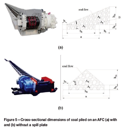
In Figure 5a, the maximum cross-sectional dimension ( Ad) of the coal conveyed can be described by:
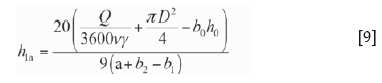
where A\, A2, and A3 are the cross-sectional dimensions of coal piled in the pan, coal blocked by the spill plate, and coal in the guiding tube, respectively; h0, b0, and b1 are the internal height, width, and thickness of the pan, respectively; h1a is the clear height of coal blocked by the spill plate; b2 is the distance from the spill plate to the outer edge of the pan; D is the diameter of the guiding tube; and Ce is the loading coefficient, the value of which is usually 0.9 (Nie et al., 2015).
In Figure 5b, the maximum cross-sectional dimension ( Aw) of the coal piled on the AFC can be described as follows:
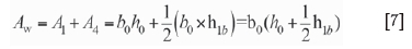
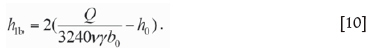
where A4 is the cross-sectional dimension of coal piled in a pan without a spill plate and h1b is the clear height of coal blocked by the spill plate.
The relationship between Q (the maximum coal-transporting capacity of the AFC) and A (the cross-sectional dimension of coal piled on the AFC) can be described as follows (Nie et al., 2015):

where v is the speed of the chain, A is the bulk density of coal piled on the AFC (taken as 0.9 (Nie et al., 2015)), and у is the density of the coal.
Combining Equations [6] and [8]:
Combining Equations [7] and [8]:
Supposing a is the angle of repose of coal piled on the AFC, then the maximum heights of coal piled on the AFC with and without a spill plate can be described, respectively, as follows:

For LFMWF 9303, a = 35°, v = 1.2 m/s, у = 1.35 t/m3, Qmax = 1800 t/h, b0= 1 m, h0= 0.352 m, and the AFC used has no spill plate, as shown in Figure 5b; therefore, the maximum height is given by:

This means that the cross-sectional dimensions of the coal piled on the AFC can satisfy the yield requirement for LFMMTS.
Structural modification of shearer A
Heightening of slippers of shearer A
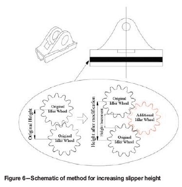
In LFMMTS, more coal gets through the clearance between shearer A and the AFC, which may cause deposition of coal and gangue plugging. To enlarge the clearance, the slipper height of shearer A needed to be increased by adding one idle wheel that can transmit the same power as the original. The method of increasing the slipper height is shown in Figure 6.
With continuous coal cutting and loading, the maximum coal-transporting capacity of the AFC (Q) can be described by Equation [8]. In production practice at LFMWF 9303, Qm= 937.5 t/h, v = 1.2 m/s, у = 1350 kg/m3. The value of A can then be obtained: A = 0.16 m2.
The underneath clearance should satisfy the following equation:
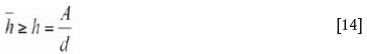
where h is the clearance actually needed; h is the theoretical clearance; and d is the centre distance of the chain and has a value of 0.26 m.
Substituting the values of A and d into Equation [14] gives h > 0.61 m. Suppose that the initial height of the slippers is l, then the height increase from this modification should be equal to h -1. In production practice, the slipper height of shearer A was increased by 0.219 m.
Increasing drum diameter of shearer A
Owing to the increase in the height of the shearer slippers, the drums of shearer A cannot reach and cut the coal at the bottom of the coal wall. To avoid this problem, the drum diameter has to be increased. The necessary increment of the drum diameter can be described as:
For the slipper increment of 0.219 m, the drum diameter should theoretically be increased by 0.438 m. In LFMWF 9303, the actual increment of the drum diameter is 0.428 m, which was essentially coincident with the theoretical value.
Coal-cutting task allocation for two shearers
Same travelling direction mining
Mathematical model for travelling distance of shearer A
The task allocation model for two shearers when using the STDM technique is shown in Figure 7. The key to this technique is to determine the correct placement of shearer B. To ensure that all the coal in a working face can be cut, shearer B should be placed within the range that can be reached by shearer A.
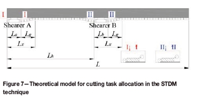
To save time in a cutting cycle, the mining times of the two shearers should be equal. An equation for mining time can then be obtained:
where L is the width of the working face; Lhis the longest distance of shearer A from the head drive; Lg is the length of the AFC bending section; Lais the length of shearer A; Lbis the length of shearer B; Vxa, Vxb, and Vkare the haulage speeds for inclined shuffle, cutting the triangular area, and of the shearer when not cutting coal, respectively; and Va and Vbare the haulage speeds of shearers A and B for regular cutting, respectively.
Because shearers A and B are the same dimensions, Lais equal to Lb. From Figure 7, the following equation can be obtained:

Because Vxa, Vxb, and Vkare slow and easily controlled, we assumed that these parameters are also equal for the two shearers. The following equation can then be obtained:
Equation [17] can be simplified by substituting Equation [19]:
An equation for Lh can then be described as follows:
Determination of placement of shearer В
In actual production, the cutting capacity of a shearer depends on the carrying capacity of transport equipment. In LFMWF 9303, the equipment with the least transport capacity is the belt conveyer, which has a carrying capacity of 1600 t/h. To ensure that the belt conveyer is not overloaded, the total cutting capacity of the two shearers must be less than its carrying capacity. Therefore, the combined mining speed of the two shearers should be less than 9.6 m/min. Furthermore, owing to the speed limit for pulling supports, the range of haulage speeds for the shearers is 3.6 to 6 m/min. Equation [21] can therefore be simplified as follows:

Using the limit equilibrium method, the range that can be reached by shearer A can then be obtained as follows: (i) when Va is equal to 6.0 m/min, the maximum value of Lhis 196.9 m, which means that the furthest travelling range of shearer A will be 196.9 m away from the head drive; (ii) when Vais equal to 3.6 m/min, the minimum value of Lhis 133.1 m, which means that the nearest travelling range of shearer A is 133.1 m from the head drive.
According to engineering data, the haulage speed of a shearer satisfies a normal distribution, Va - N(4.8,0.28), and satisfies - u| < 3δ} = 0.9974, so the probability of Va satisfying P{3.21 < Va< 6.39} is 0.9974. The haulage speed range of shearer A (3.6 to 6.0 m/min) is an event with large probability, which is consistent with the actual speed requirement.
In the STDM technique, suppose that Lpis the advance distance of shearer A at the end of one working cycle, then a historical curve of Lh corresponding to Lpcan be drawn. The historical curve of Lhis in production practice is shown in Figure 8.
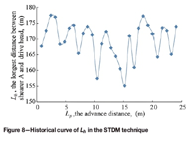
When LFMWF 9303 uses the STDM technique, the distance between shearer A and the drive head is in the range of 154 m to 177 m after a working cycle, as obtained from Figure 8. Therefore, the initial arranged placement for shearer B should be in the same range to ensure that the sum of two shearers' movement ranges is equal to the width of the working face.
Opposite travelling direction mining
Mathematical model for meeting
The meeting of the two shearers is a crucial problem that needs to be resolved when employing the OTDM technique. As too small an interval between the two shearers may cause the shearers' drums to crash into each other, a safe distance is needed to avoid their meeting. A theoretical meeting model for two shearers is shown in Figure 9.
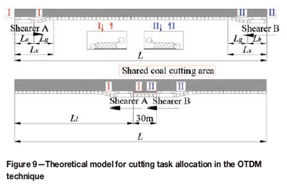
Suppose that the mining time of the two shearers is equal, then the following equation can be obtained:
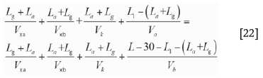
where L1 is the distance from shearer A to the head drive when the distance between two shearers is equal to 30 m. The other parameters are as defined for Equation [16].
The same shearers and AFC are used in both the STDM and OTDM techniques, so Equations [17] and [18] can also be used for the OTDM technique. Equation [22] can then be simplified as follows:
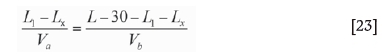
An expression for L1 can be given as follows:
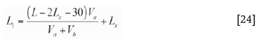
Determination of the meeting position of two shearers
The haulage speed of each shearer ranges from 3.6 m/s to 6.0 m/s and since the values of the other parameters are fixed, then Equation [24] can be simplified as follows:

The value of L1 ranges from 121.82 m to 178.64 m away from the head drive. Shearer A is in the range of hydraulic supports no. 80 to 118. According to the value of Va, there are two cases for describing the equation for the meeting position. (i) If Va is less than 4.8 m/min, the two shearers will meet closer to the head drive. In this case, shearer A should continue mining towards the tail drive until the shared coal-cutting area is completely cut, while shearer B
should have an inclined shuffle towards the tail drive. The equation for the meeting position can be described as follows: Lm= L1 + 30 (where Lmis the distance between shearer A and the head drive when two shearers meet). (ii) If Va is greater than 4.8 m/min, then the two shearers will meet closer to the tail drive. In this case, shearer B should continue mining towards the head drive until the shared coal-cutting area is completely cut, while shearer A should have an inclined sump towards the head drive, and now, Lm= L1.
The historical curve of Lmcorresponding to Lpwhen using the OTDM technique in production practice is shown in Figure 10.
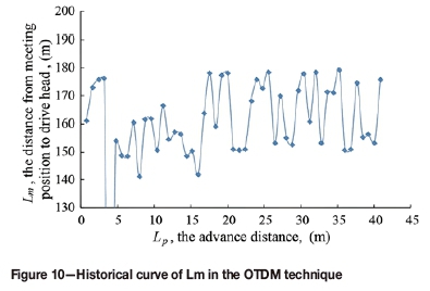
As shown in Figure 10, when two shearers meet in the middle of the working face, the distance between the shearers and head drive ranges from 140 to 180 m. Because the meeting position is in the middle of the face, the rock pressure is higher, which makes it more difficult to support (Liu et al. 2016). More attention should therefore be paid to rock pressure and workers' safety at the meeting position.
Application of the two-shearer concept
Comparison with a single-shearer working face
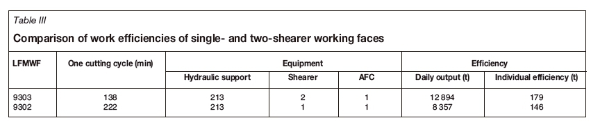
LFMWF 9302 is a single-shearer fully mechanized working face located adjacent to and east of LFMWF 9303, and the geological conditions of two working face are similar. The width of LFMWF 9302 is 330 m, and the model of shearer, hydraulic support, and AFC are the same as those of LFMWF 9303. The main difference between two working faces is the number of shearers used. The work efficiencies of LFMWF 9303 and 9302 are shown in Table III. Compared with LFMWF 9302, the time of a single cutting cycle in LFMWF 9303 was reduced by 84 minutes, the workers' efficiency increased by 33 t per person, and the daily output increased by 4537 t (54%). Furthermore, the distance that the workers need to walk is less because the travelling distance of each shearer is shorter in a double-shearer face.
Direct economic benefits of two-shearer working face
The super-long two-shearer face is merged from two ordinary faces. With this design, one 3.5 m wide pillar and two 1900 m long gateways are not required, which gives a saving of $6.05 million on each working face layout. In addition, the number of workers on a two-shearer face is just 1.3 times that of a one-shearer face, in other words, just 62.5% of that of two single-shearer faces, which saves about $0.476 million annually on labour costs. So with LFMMTS, the production cost was decreased by $6.526 million in total. In addition, the net profit from per ton coal was $5.05. As the daily output of LFMWF 9303 was increased to 12 894 t, the daily net profit that No. 2 Jining Mine obtained from LFMWF 9303 was more than $65 000.
Conclusion
To enable high production and high efficiency in ageing coal mines, while still using existing mining equipment, a new technical scheme, named LFMMTS, is proposed. This involves mining using shearers travelling in either the same direction or in opposite directions. The mining processes for the two techniques are described. This scheme has been successfully applied in LFMWF 9303 of Jining Mine and yielded a 54% increase in output.
Theoretical models to determine the MSL and check the cross-sectional dimensions of the AFC were built. A 30 m safe distance, named the shared coal-cutting area, in LFMWF 9303 was employed to avoid AFC accidents involving chain rupture or compression of the pans. The structure of the shearer closer to the head drive was modified to satisfy the transportation demands of an LFMMTS face, including increasing the slipper height and drum diameter by 0.219 m and 0.428 m respectively.
Theoretical models for coal-cutting task allocation for the two mining techniques were constructed, based on equal mining times for each shearer in a single cutting cycle. For the case of LFMWF 9303, when using the STDM technique, shearer B should be arranged in the working face at a distance of 154 m to 177 m from the head drive, which is where shearer A can reach; when using the OTDM technique, the meeting positions range from 140 m to 180 m away from the head drive.
Acknowledgements
Financial support for this work was provided by the National Key R&D Program of China (No. 2018YFC0604701), the Natural Science Foundation of Jiangsu Province (No. BK20181358),a scholarship from the China Scholarship Council and the Priority Academic Program Development of Jiangsu Higher Education Institutions. We thank Kathryn Sole, PhD, from Liwen Bianji, Edanz Group China (www.liwenbianji.cn/ac), for editing the English text of a draft of this manuscript.
References
Alvarez, J.T., Rodriguez, R., Rivas, J.M., and Casal, M.D. 2003. GEWINNUNG-Economic and technical results mining a 4 m thick coal seam in Spanish Carbonar colliery. Gluckauf, vol. 139, no. 6. pp. 323-328. [ Links ]
Bolilasi, L.J. and Zhao, C.J. 1985. Mining with two continuous miners. Coal Technology, vol. 4, no. 4. pp. 2-46. [ Links ]
Ceng, X.W., Wang, F.J., and Guo, Z.C. 2016. Feasibility analysis and application of bidirectional coal mining technology of double coal machine. Inner Mongolia Coal Economy, vol. 14. pp. 113-114. [ Links ]
Edwards, J.B. 1981. The modelling of semiflexible conveyor structures for coalface steering investigations. ARCHIVE Proceedings of the Institution of Mechanical Engineers 1847-1982, vol. 1-196, no. 196. pp. 387-400. [ Links ]
Edwards, J.B., and Yazdi, A.M.S.R. 1983. Modelling the steering characteristics of coal face conveyors by random signal testing. IFAC Proceedings, vol. 16, no. 15. pp. 561-570. [ Links ]
Fu, Y.P., Song, X.M., and Xing, P.W. 2010. Study of the mining height of caving zone in large mining height and super-long face of shallow seam. Journal of Mining & Safety Engineering, vol. 27, no. 2. pp.190-194. [ Links ]
Hu, X.J., Meng, X.R., and Zhu, J.M. 2008. Geological condition evaluation system of high yield and high efficiency mines. Coal Mining Technology, vol. 26. pp. 947-953. [ Links ]
Ju, J., Xu, J., and Zhu, W. 2015. Longwall chock sudden closure incident below coal pillar of adjacent upper mined coal seam under shallow cover in the Shendong Coalfield. International Journal of Rock Mechanics & Mining Sciences, vol. 77. pp. 192-201. [ Links ]
Jurecka, H. 1987. Experience with the Edw 450l shearer in a thick seam at Ensdorf colliery. Gluckauf, vol. 123. pp. 282-289. [ Links ]
Kulshreshtha, M. and Parikh, J.K. 2001. A study of productivity in the Indian coal sector. Energy Policy, vol. 29, no. 9. pp. 701-713. [ Links ]
Kulshreshtha, M. and Parikh, J.K. 2002. Study of efficiency and productivity growth in opencast and underground coal mining in India: a DEA analysis. Energy Economics, vol. 24, no. 5. pp. 439-453. [ Links ]
Li, Z.H., Hua, X.Z., Zhu, R.J., and Zhou, D.S. 2013. Numerical simulation of strata behavior in super-long and large mining height working face. Advanced Materials Research, vol. 634-638, no. 1. pp. 3428-3432. [ Links ]
Liu, Y., Zhou, F., Geng, X., Chang, L., Kang, J., Cui, G., and Zhang, S. 2016. A prediction model and numerical simulation of the location of the longwall face during the highest possible failure period of gob gas ventholes. Journal of Natural Gas Science & Engineering, vol. 37. pp.178-192. [ Links ]
Mishra, D.P., Sugla, M., and Singha, P. 2013. Productivity improvement in underground coal mines - a case study. Journal of Sustainable Mining, vol. 12, no. 3. pp. 48-53. [ Links ]
Nie, R., He, B.Y., Yuan, P.F., Zhang, L.H., and Li, G.P. 2015. Novel approach to and implementation of design and analysis of armored face conveyor power train. Science China Technological Sciences, vol. 58, no. 12. pp. 2153-2168. [ Links ]
Niu, X.Y. 2009. Feasibility analysis of coal mining with double shearers in extended working face. Shaanxi Coal, vol. 28, no. 1. pp. 29-30. [ Links ]
Qu, Q.D., Xu, J.L., and Xue, S. 2009. Improving methane extraction ratio in highly gassy coal seam group by increasing longwall panel width. Procedia Earth & Planetary Science, vol. 1, no. 1. pp. 390-395. [ Links ]
Robbins, R.J. 2000. Mechanization of underground mining: a quick look backward and forward. International Journal of Rock Mechanics & Mining Sciences, vol. 37, no. 1. pp. 413-421. [ Links ]
Torano, J., Diego, I., Menéndez, M., and Gent, M. 2008. A finite element method (FEM) - fuzzy logic (soft computing) - virtual reality model approach in a coalface longwall mining simulation. Automation in Construction, vol. 17, no. 4. pp. 413-424. [ Links ]
Tu, S.H., Yuan, Y., Zhen, Y., Ma, X.T., and Qi, W. 2009. Research situation and prospect of fully mechanized mining technology in thick coal seams in china. Procedia Earth & Planetary Science, vol. 1, no. 1. pp. 35-40. [ Links ]
Walker, A.J. 1987. The development and use of very heavy duty face conveyors. Advances in Mining Science & Technology, vol. 1. pp. 199-211. [ Links ]
Wu, S.H. and Zhang, H.L. 2012. Practical application of double-shearer in fully mechanized face with soft rock condition. Shandong Coal Science and Technology, vol. 4. pp. 23-23. [ Links ]
Xu, J.L., Yu, B.J., Lou, J.F., and Wang, D. P. 2007. Characteristics of gas emission at super-length fully-mechanized top coal caving face. Journal of China University of Mining and Technology, vol. 17, no. 4. pp. 447-452. [ Links ]
Zhang, D., Zhang, M., and Wang, B. 2000. Analysis and selection of mining patterns for high-output-and-high-efficiency mines. Journal of China University of Mining and Technology, vol. 29, no. 4. pp. 363-367. [ Links ]
Zhang, Y., Wan, Z.J., Li, G.W., and Wang, C. 2009. Idea on combined coal mining technology with multi coal shearers for longwall coal mining face. Coal Engineering, vol. 10. pp. 8-11. [ Links ]
Zhao, Y.H., and Song, X.M. 2016. Stability analysis and numerical simulation of hinged arch structure for fractured beam in super-long mining workface under shallow seam. Rock & Soil Mechanics, vol. 37, no. 1. pp. 203-209. [ Links ] ♦
Paper received Dec. 2017
revised paper received Jun. 2018

