


Services on Demand
Article
 English (pdf)
 Article in xml format
 Article references
Indicators

Related links
-
 Cited by Google
 -
 Similars in Google
Share

 Permalink
Journal of the Southern African Institute of Mining and Metallurgy
On-line version ISSN 2411-9717
Print version ISSN 2225-6253
J. S. Afr. Inst. Min. Metall. vol.118 n.8 Johannesburg Aug. 2018
http://dx.doi.org/10.17159/2411-9717/2018/v118n8a13
PAPERS OF GENERAL INTEREST
A preliminary qualitative evaluation of a hydraulic splitting cylinder for breaking rock in deep-level mining
W.W. de Graaf; W. Spiteri
Department of Mining Engineering, University of Pretoria, South Africa
SYNOPSIS
Hydraulic rock-splitting cylinders have proved successful in numerous civil and construction applications. The purpose of this study was to conduct a preliminary qualitative evaluation of the applicability of the hydraulic splitting cylinder in deep-level mining with the aim of recommending equipment modifications and operational practices. The particular instrument used in the study was the DARDA® hydraulic splitter.
Conventional drill-and-blast practice in deep-level mining often impacts adversely on the immediate environment. Alternatives are periodically sought for efficient, continuous, and safe rock-breaking in situations where conventional blasting is undesirable. A considerable amount of investigation work has been conducted by mining companies, equipment manufacturers, and research institutions on numerous methods of non-explosive mining, including the use of the hydraulic rock-splitter.
Several trials were conducted underground. The most challenging aspect of in mechanical rock-splitting is to create a second free face in the stope, and the trials evaluated four different 'cut' layouts to achieve this objective. The trials highlighted the limits of the equipment in its current phase of development, as well as the importance of quality drilling in terms of collaring the hole, hole length, and directional accuracy. In the presence of a second free face the splitter becomes far more effective. The unit is simple in design and is easily integrated into existing mining operations. It also does not require a technically skilled workforce or expensive maintenance.
Rock-breaking with the use of a rock splitter could have a place in niche applications in an underground mining operation, with some equipment modifications and further development of the process to establish a free-breaking face. General operational difficulties experienced underground during the trials are summarized and possible solutions recommended.
Keywords: rock-breaking, mechanical splitting, hydraulic splitter.
Introduction
For several decades research has been undertaken to develop viable alternative methods to the use of high-energy explosives for breaking rock and general mining (Haase and Pickering, 1991; Murray, Courtley, and Howlett, 1994). The motivating factors have predominantly been related to allowing continuous mining operations without interruption, and reducing the environmental impacts such as blast-induced ground vibrations, air blast, post-blast noxious fumes, flyrock, and damage to the surroundings (Singh, 1998). In underground mining operations, safety considerations such as the triggering of falls of ground, damage to the side- and hangingwalls, and blast-induced seismic activity also feature prominently. Res, Wladzielczyk, and Ghose, (2003) and Ramezanzadeh and Hood (2010) reviewed and summarized progress to date on the subject. There are, however, minimal literature references on the use of hydraulic splitters in underground mining.
In South Africa particularly, underground mining has now reached unprecedented depths with numerous associated challenges, and the cost of mining at these depths has increased correspondingly. As a result, the major mining companies are conducting serious investigations looking at all aspects of modernization, including mechanization, automation, and robotics, to alleviate the challenges of mining underground at great depths. Drill-and-blast mining is difficult to automate, presenting yet another reason for the continuing search for a viable alternative.
The work conducted in this investigation was aimed at a preliminary qualitative evaluation of the use of a hydraulic splitter in underground mining and to recommend possible modifications to equipment and to operating methods. There was no intention to evaluate the efficiency of the system as a method of continuous mining. Furthermore, as the object was to investigate the suitability of the equipment, no time-and-motion studies were carried out. Rather, the splitter is seen as a potential candidate for non-explosive rock-breaking in niche applications where conventional blasting techniques are not possible or desirable. The choice of the mechanical splitter, as opposed to other nonexplosive rock-breaking systems, for this study was motivated by the following: the device has been used successfully in the civil and construction industries; the systems are readily available and affordable; the application of the splitter is similar to the application of drilling equipment, hence available infrastructure can be used and minimal training of personnel is needed; and the equipment is relatively simple to maintain.
As described by Murray, Courtley, and Howlett (1994), there are two subgroups of mechanical splitters - the wedge-and-feather splitters and the radial axial splitters. The radial axial splitter simply differs from the normal wedge/feather splitter, such as the one used in this study, in that the feathers are moved outwardly by a retracting rod as opposed to a protruding rod. The particular instrument used in this work was the wedge-and-feather splitter supplied by DARDA®. The choice was based solely on commercial availability.
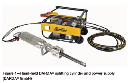
The DARDA® splitting cylinder
The detailed description and specifications of the various DARDA® splitting cylinder device is given on the company's web site (http://www.darda.de). Figure 1 shows the DARDA® splitting cylinder and power supply.
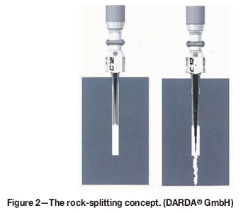
Essentially, the concept makes use of the wedge principle, whereby a borehole is initially drilled into the material (concrete, rock), then the DARDA® splitter wedge set (two counter-wedges or feathers and a central wedge) is inserted into the hole. The central wedge is then driven forward between the two feathers under hydraulic power, forcing the feathers outward against the walls of the hole. Radially loaded stress build-up is created that fractures the rock. The DARDA® hydraulic unit will apply a pressure of up to 400 t to force the feathers apart (see Figure 2) (Anderson and Swanson, 1982; Duncan and Langfield, 1972; Paraszczak and Hadjigeorgiou, 1994). A detailed mathematical analysis of the stresses induced on the rock by the splitter was done by Chollette, Clark, and Lehnhoff (1976).
According to the DARDA® web site, the benefits of hydraulic splitting include controlled breaking without the adverse side-effects seen with impact breakers or conventional explosives.
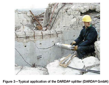
The DARDA® splitter has been successfully applied in the general civil demolition field for breaking and splitting concrete and rock. A typical application of rock-splitting on surface is shown in Figure 3.
The splitting unit is manufactured from steel and aluminium to reduce the weight. The control valve will either extend or retract the centre wedge. The wedges are manufactured from steel coated with a carbide layer for increased durability.
The hydraulic pump delivers a maximum pressure of 50 MPa to the splitter. The pressure is controlled through a pressure limiting valve. Different drive systems are available for various applications and can be either electric, air, diesel, or fuel motors.
During these trials, a 220 V electric motor was used to drive the hydraulic power pack.
The DARDA® splitter is constructed for use in robust environments. The material properties of the components, and the extremely high forces exerted to fracture the rock mass, impose certain restrictions on the equipment size and weight, which in turn impose limits on the operability, such as the minimum hole diameter. The C12L model splitting cylinder was used during these underground trials. This unit weighs 32 kg and is approximately 1.3 m in length, which is not very different to the weight and proportions of a rockdrill. The applicable hole diameter ranges between 45 mm and 48 mm. The two feathers, or counter-wedges, are 450 mm in length. However the minimum hole length required is 680 mm, to accommodate the extending centre wedge.
Field work
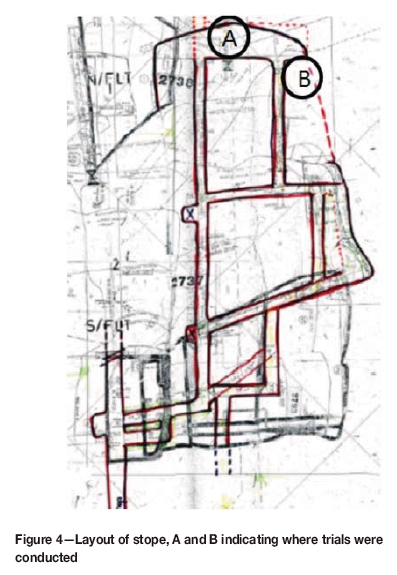
Trials were conducted over a period of five months at the then Gold fields KDC West Gold Mine - Pitseng shaft. A non- production stope was established on 24 level where several new mining initiatives could be trialled and tested. The stope width was on average 1.5 m in unfractured footwall quartzite with a uniaxial compressive strength (UCS) of 160 MPa (personal communication - Professor F. Malan, University of Pretoria). The stope was equipped with the necessary services, including water, compressed air, electricity, and WiFi connections for communication.
Figure 4 shows where the tests were carried out on the rock face: position A in the absence of a second free face, and position B adjacent to the gully, where a second free face was present. During the trials, drilled holes were grouped into one of two categories, either 'cut' for the creation of a second free face or 'slicing' for breaking the rock along the second free face.
All the proposed cut designs were carefully marked on the face and the drilling accuracy was measured and noted. The accuracy of drilling was determined with the use of a clino-rule for measuring the angles, hole depth, and horizontal and vertical distances between the holes. A simple hand-held spring scale was used to measure the amount of rock broken. Still photography and video footage of all splitting operations was taken.
The 'cut' holes:
The hole layouts for splitting were based on conventional drilling and blasting knowledge and experience, as well as established techniques for the use of the splitter in surface mining and demolition applications. In mining terms the 'cut' is a pattern of drilled holes in the rock face, used to create a second breaking face. In conventional drill-and-blast operations, the 'cut' drill pattern differs from the production drill pattern in hole layout, drilling angle, and initiation timing of the blast-holes. The sole purpose of the 'cut' is to create a second breaking face into which successive production holes will break outwards to the perimeter of the excavation. A large variety of 'cut' designs have been proposed for mechanical splitting; for example the US Bureau of Mines (Anderson and Swanson, 1982) suggested the spiral-shaped round drill pattern, whereas Clark and Maleki (1978 recommended a similar method to the V-cut used in an explosive round.
Breaking rock using the DARDA® splitter is a much slower process than blasting. The rock around each hole has to be individually fractured until it breaks into an adjacent drilled hole or a void. Holes must be concentrated in the 'cut' area to facilitate the creation of the second free face. In this investigation, the void area was drilled according to several proposed hole layouts. These layouts included a few designs with holes drilled at an angle, a few combinations of straight and angled holes, and designs where larger holes were included in the cut pattern. The intention was that the larger holes would act as a 'mini-cut' into which the splitter holes would break.
A number of drill patterns to create the cut were carefully considered. As the holes have to be drilled to a minimum depth to accommodate the fully extended central wedge, holes drilled perpendicular to the advancing face had the advantage that they could be deepened and used again for splitting.
In conventional drill-and-blast tunnel development, creating the cut requires a high concentration of explosive energy (Atlas Powder Company, 1987) hence the high concentration of blast-holes. Once the 'cut' has been created, hole burdens can be increased because a second free face is now present. In order to reduce drilling time during these trials, an attempt was made to create the most efficient hole layouts for the 'cut' area in terms of the least number of holes for effective breaking using the DARDA® splitter.
As mentioned, the holes were drilled to a length that would accommodate the protruding centre wedge. After the first round of breaking the remains of each hole would be deepened for the next round. Holes drilled at an angle could not be deepened, as they would extend beyond, and break outside, the perimeter (see Figure 5).
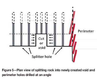
The one area where angled holes would be necessary would be in the case of perimeter holes, i.e. holes on the edge of the stope. These holes would have to be drilled at a slight angle, referred to as the 'look-out' angle (Cooper, Berlieand, and Merminod, 1980). The holes would be collared inside the planned perimeter and angled outwards with the toe of the hole situated on the outside of the perimeter (see Figure 5) to accommodate the centre wedge of the splitter and also to retain the contours of the stope. In these trials, perimeter holes were not drilled or investigated.
During this investigation four cut designs were considered and tested underground. These four trial patterns were chosen based on simplicity of the drilling pattern and the minimum holes drilled per cut, and are described below.
Cut-hole layout 1
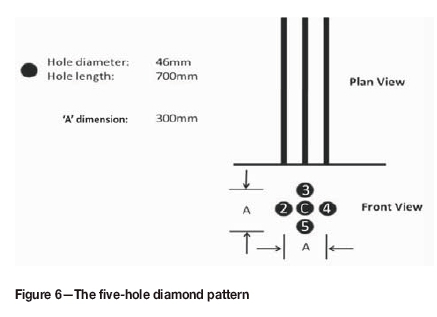
The cut-hole layout 1 drilling pattern consisted of five parallel holes to create the 'cut'. The four outer holes were drilled on a 300 mm diamond pattern (Figure 6). The fifth hole was drilled in the centre of the diamond. The holes were drilled to a minimum depth of 700 mm.
Cut-hole layout 2
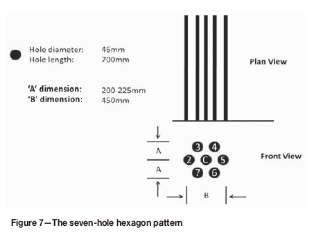
The second pattern trialled consisted of seven holes. All the holes were drilled to a depth of 700 mm, parallel to one another and perpendicular to the stope face. The outer holes were drilled in a hexagon pattern with dimensions of 450 mm (Figure 7). One hole was drilled in the centre. Breaking was initiated by inserting the splitter in the centre hole, hole 'C'.
Cut-hole layout 3
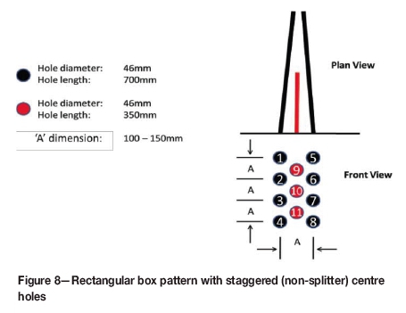
Figure 8 shows a drilling pattern of 11 holes. The eight outer holes were drilled in a rectangular box pattern to a minimum length of 700 mm. The outer holes converged to the centre row of holes at an angle of between 3° and 6° to the perpendicular. Three holes were drilled to a depth of 350 mm, and parallel to one another, between the two outer rows of holes. The splitter was inserted in the outer holes and the inner holes acted as 'break' or 'relief' holes.
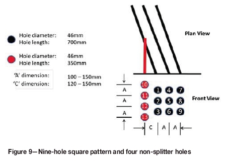
Cut-hole layout 4
Figure 9 shows another combination of perpendicular holes and angled holes. The perpendicular 'relief' holes were drilled parallel to one another, and perpendicular to the rock face to a short depth of 350 mm. The angled holes (700 mm depth), into which the splitter was inserted, were drilled as a rectangular nine-hole pattern converging towards the perpendicular short holes at an angle of between 19° and 23° to the perpendicular, the angles being dictated by the ease of collaring and to minimize the burden between the first row of angled holes and the adjacent perpendicular holes (dimension C in Figure 9). The splitter was initially inserted in hole number 2.
The production or 'slicing' holes:
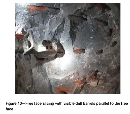
Two trials were carried out in an area of the stope where the second free face had previously been created by blasting. The rock face was scrutinized and the position of each hole was carefully selected and marked and drilled parallel to the second free face (as per Figure 4, position B and as shown in Figure 10). No plans were presented for the production holes; instead, the pattern was determined according to the face conditions. The distance between any production hole and the free face (burden) varied from 300 mm to a maximum of 500 mm. The results are discussed in the next section.
Results and observations
The observations for each individual test were noted during the trials and further analysed in conjunction with the video footage. One critical common observation from all the tests was the dependence on accurate drilling in terms of the collar position and direction. With divergence of hole direction from the planned pattern, the amount of rock that has to be cracked and broken may increase, hence reducing the performance of the splitter.
Cut-hole layout
Hole layout 1
The DARDA® splitter was inserted into the centre hole ('C' in Figure 6). As the wedge was extended, no visual cracking or breaking of the rock mass was observed. The wedge was retracted and inserted in hole 2 of the pattern. This hole was randomly selected, and as the splitter's centre wedge started extending, some minor cracking developed between the splitter hole and the centre hole. The DARDA® splitter was then removed from the hole and inserted into hole number 3. As the wedge started protruding, more visible cracks developed towards the left and centre holes. The diameter of the centre hole decreased due to the fracturing in the centre of the 'diamond' and the 'swelling' of the rock mass. The same effect was observed when the splitter was inserted into holes 4 and 5. During the splitting process some small rock fragments fell to the footwall; however, the majority of the fragments had to be removed manually. The cut advance produced 30 kg of rock with an average depth of 36 cm (compared to the splitter's feather length of 45 cm).
Hole layout 2
The DARDA® splitter was similarly inserted into the centre hole ('C', Figure 7). As per the five-hole diamond pattern (layout 1), initially no visual cracking or fracturing occurred. The splitter was then inserted into hole 2 of the pattern. As the wedge was extended, visible hairline cracks developed towards the centre hole. Inserting the splitter into hole 3 caused increased cracking, but not sufficiently for fragments to easily fall to the footwall. The splitter was inserted into all the holes and random hairline cracking was noted. However, attempts to break and loosen the rock were unsuccessful. The splitter was then re-inserted in turn into each of the holes. During this process visible fracturing of the rock was noted and some small fragments fell to the footwall. The DARDA® splitter was removed and the void area was cleaned by removing the loose fragments using a steel rod. This cut design produced 35 kg of rock fragments with an average depth of 38 cm.
Hole layout 3
In hole layout 3 the drilling was slightly more complex than in layouts 1 or 2.
The DARDA® splitter was inserted into hole number 2 (Figure 8) of the drilled pattern. Immediately after the centre wedge started protruding a fracture developed diagonally across the centre hole, hole 9, and hole 5. Upon closer inspection it was evident that there was an existing fracture in the area where the holes were drilled. This existing fracture assisted the splitting process, consequently all the holes into which the splitter was inserted generated cracks. Even in this case, however, fragments had to be removed by inserting a steel rod into the cut area and wedging the piece out until the entire area was cleared. This cut design produced 38 kg of rock fragments to a depth of 35 cm.
Hole layout 4
In this particular test, the uneven nature of the face created problems during the drilling of the nine-hole pattern, and the holes were not collared on the marked positions. This was, however the only suitable area for the trial.
The splitter was initially inserted into hole 2 of the nine-hole grid (Figure 9). As the centre wedge was extended, fractures developed between hole 2 and 11 and between hole 2 and hole 12. The same result was observed when the DARDA® splitter was inserted in holes 1 and 3. Again, small rock fragments fell to the footwall but the balance of the fragments had to be removed by hand. The splitting of the grid holes, holes 4 to 8, was difficult due to the large variation between the marked position and actual drilled position of each hole. Hole 9 was abandoned due to the splitter not being able to create any fractures during the splitting process. Some 65 kg was removed from the void area. The larger amount of rock removed compared to the other cuts was due to the larger cross-sectional area mined. The average depth of the cut was 28 cm.
Production or 'slicing' holes
The distance from the free face to the splitter hole position varied between 200 mm and 500 mm. Any existing cracks visible in the rock mass were used to assist in the breaking process. Compared to the 'cut-hole' trials, a relatively higher success level was achieved in breaking rock chunks towards the free face. The majority of the fragments broke on existing fractures. Initially the distance of the holes from the free face was set at 200 mm but as the trials progressed and breakage was achieved easily, the distance was incrementally increased to 500 mm. Spalling of the rock into the second free face was quick and effortless for the splitter and at the same time cracks appeared behind the row of holes, which were exploited in the second round of drilling and splitting.
Discussion
The underground trials identified the limits as well as the potential of the DARDA® splitter in this application. A number of lessons were also learned, including the need for drilling accuracy. Operational aspects of the DARDA® splitter and the results achieved are discussed in the following sections.
Cut-hole trials
As mentioned above, creating the cut or second free face is a crucial step allowing for efficient subsequent rock-breaking into the newly established free face. Within the confines of the various cut patterns trialled in this investigation, difficulty was found with the use of the splitter. Of the four patterns tested, none was shown to be significantly better than the other three in terms of ease of establishing the initial cut. Certain factors need to be considered in the design of the cut, particularly the need to minimize the number of holes required so that drilling time is kept to a minimum. The five-hole burn cut was drilled in the shortest time, but produced the least amount of broken rock. The greater the initial cross-sectional area of the cut, the easier it is to split the following holes (which now become 'slicing' holes). The pattern of holes extending radially outwards around the cut area can then be wider, i.e. with holes further apart. Furthermore, by increasing the cross-sectional area of the cut, broken fragments are removed more easily from the created void. In general, however, creating an initial second face or 'cut' using the splitter has been found difficult to achieve and none of the four cut patterns tested gave satisfactory results. A possible solution would be to increase the number of holes and decrease the distance between them to create the initial cut. An alternative would be to increase the diameter of non-splitting holes. This field needs further investigation.
Slicing hole trials
The splitter was found to be more effective for the slicing operation. These tests proved that once a second free face has been established, the use of the splitter becomes more viable and efficient.
General discussion
Drilling accuracy
Drilling of the holes in the rock face for the use of the splitter posed some specific challenges compared to drilling for blasting operations. These issues could, however, be fairly easily rectified. Hole length is crucial as the DARDA® splitter extends the centre wedge into the hole and it should be able to move freely and not be obstructed by the toe of the drilled hole. A hole that is drilled too short will destroy the centre wedge. The hole diameter should be equal to or slightly greater than the specified diameter of 46 mm. Inserting the splitter into a hole with a diameter less than 46 mm is not possible. Holes need to be drilled as straight as possible. This was highlighted when an early test hole deviated from the planned direction and the splitter centre wedge was consequently bent. Furthermore, as mentioned above, inaccurate drilling can drastically affect the performance of the splitter.
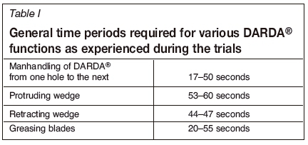
Breaking cycle
Although, no detailed time studies were done during the trials, several relevant time periods were noted for interest and future reference (see Table I).
DARDA® splitter operational learnings
Several challenges were experienced with the equipment during the initial trials, causing the cycle to take longer than planned.
► Firstly, proper lubrication of the feathers and wedge is critical, and in these trials the feathers and wedge were lubricated approximately every fifth hole. The feathers were manually opened and the lubricant was squeezed between the moving parts. This was time-consuming and slowed down the entire process. It is suggested that this process be automated by installing a greasing device on the DARDA® splitter, which may also increase the usable life of the moving parts.
► The DARDA® splitter also had to be supported when inserted into the hole. During the fracturing process, it was found that as the rock broke away from the hole perimeter, the feathers were exposed and the unit fell to the ground. The unit was supported by tying a rope to the handle of the splitter and suspending it from the safety netting used in the stope. A supporting rig would be advisable.
► On a few occasions some small rock fragments were caught between the feathers and the wedge as the splitter was withdrawn from a hole. These fragments needed to be removed manually before the wedges could be inserted into the next hole.
► When the rock mass did not give way during fracturing, removing the DARDA® splitter from the hole was extremely difficult and a pinch bar was needed to open fractures and allow the wedges to be dislodged.
► On a few occasions the splitter's feathers did not 'grip' against the perimeter of the hole and as the wedge was extended the DARDA® splitter moved backwards.
Other operational learnings
► During the fracturing process the rock fragments on the free face generally fell to the footwall. However the fragments deep inside the void area had to be removed using a steel rod and the last fragments were removed by hand. An improved cut design could alleviate this issue.
► The splitting process should start from the footwall of the stope face and progress towards the hangingwall. In this way the drilled holes are not obscured by rock fragments.
► During most of the trials fractures did not develop immediately after the DARDA® splitter wedge was extended. In some cases it took between two and three attempts before fracturing was observed between the splitting hole and an adjacent hole or the second free face.
Conclusions
With some improvements to the equipment and technique, rock-breaking with the use of a rock splitter could well have a place in an underground mining operation. It is suitable for niche applications, such as (but limited to) areas where conventional drilling and blasting is prohibited, in removing safety pillars and shaft pillars, and areas where seismic events are rife.
The static hand-held tool can easily be manhandled in restricted spaces. It is also simple in design, can be easily integrated into existing mining operations and infrastructure, and does not require a technically competent or skilled workforce, or expensive maintenance.
The trials showed the shortcomings of the equipment in developing the initial cut or second free face. Furthermore, the use of the splitter is highly dependent on accurate drilling. The splitter becomes more effective once a second free face is present. Future work should therefore concentrate on developing more effective techniques for creating an initial cut.
Acknowledgements
The authors would like to express sincere appreciation to the following persons who assisted and made the underground trials possible. Dr Andries Leushner, Kloof Driefontein Complex; Danie Burger, CTMI; and Ras Botma. We also thank the anonymous reviewers for comments that have greatly strengthened this paper.
References
Anderson, S.J. and Swanson, D.E. 1982. Laboratory testing of a radial-axial loading splitter. RI 8722. US Bureau of Mines. 26 pp. [ Links ]
Chollette, D., Clark, G.B., and Lehnhoff, T.F. 1976, Fracture stresses induced by rock splitters. International Journal of Rock Mechanics and Mining Sciences and Geomechanics Abstracts, vol. 13. pp. 281-287. [ Links ]
Clark, G.B. and Maleki, H. 1978. Basic operational parameters of an automated plug and feather rock splitter. Report NSF APR 73-07846-A02. Colorado School of Mines. [ Links ]
Cooper, G.A., Berlie, J., and Merminod, A. 1980. A novel concept for a rock-breaking machine II. Excavation techniques and experiments at larger scale. Proceedings of the Royal Society London, Series A, vol. 373, no. 1754, December. pp. 352-372. [ Links ]
Darda GmbH. http://ww.darda.de [accessed 23 November 2017]. [ Links ]
Duncan, N.J. and Langfield, E.R. 1972, Rock excavation by hydraulic splitter. Proceedings of the Rapid Excavation and Tunneling Conference, New York, June 1972. pp. 785-791. [ Links ]
Atlas Powder Company. 1987. Explosives and Rock Blasting. Dallas, TX. [ Links ]
Haase, H.H. and Pickering, R.G.B. 1991. Non-explosive mining: An untapped potential for the South African gold-mining industry. Journal of the South African Institute of Mining and Metallurgy, vol. 91, no. 11. pp. 381-388. [ Links ]
ISEE. 2011. Blasters' Handbook. 18th edn. International Society of Explosives Engineers, Cleveland, OH. [ Links ]
Murray, C., Courtley, S., and Howlett, P.F. 1994. Developments in rock-breaking techniques. Tunnelling and Underground Space Technology, vol. 9, no. 2. pp. 225-231. [ Links ]
Paraszczak, J. and Hadjigeorgiou, J. 1994. Rock splitting as a primary excavation technique. Tunnels and Tunneling, November 1994. pp. 49-52. [ Links ]
Ramezanzadeh, A. and Hood, M. 2010. A state-of-the-art review of mechanical rock excavation technologies. International Journal of Mining and Environmental Issues, vol. 1, no. 1. doi: 10.22044/jme.2010.4 [ Links ]
Res, J., Wladzielczyk, K., and Ghose, A.K. 2003. Environment-Friendly Techniques of Rock-Breaking. CRC Press. [ Links ]
Singh, S.P. Non-explosive applications of the PCF concept for underground excavation. Tunnelling and Underground Space Technology, vol.13, no. 3. pp. 301-311. [ Links ] ♦
Paper received Mar. 2018
Revised paper received Apr. 2018

