


Services on Demand
Article
 English (pdf)
 Article in xml format
 Article references
Indicators

Related links
-
 Cited by Google
 -
 Similars in Google
Share

 Permalink
Journal of the Southern African Institute of Mining and Metallurgy
On-line version ISSN 2411-9717
Print version ISSN 2225-6253
J. S. Afr. Inst. Min. Metall. vol.118 n.7 Johannesburg Jul. 2018
http://dx.doi.org/10.17159/2411-9717/2018/v118n7a10
PAPERS OF GENERAL INTEREST
Effect of dip on pillar strength
K.V. Jessu; A.J.S. Spearing
Western Australia School of Mines, Curtin University, Kalgoorlie, WA
SYNOPSIS
Pillars are commonly left in underground mining, either for secondary extraction after the primary stopes have been filled or to maintain the overall macro-stability of the mine during its useful life by supporting the overburden. The dip, dimensions, and geological features of an orebody determine the mining method used. If pillars are used, the orientation of pillars can vary from horizontal to vertical and anything in-between. The pillars left in underground mines can be loaded axially or obliquely (axial and shear components) depending on their orientation and that of the field stresses. Empirically established methods or numerical modelling are used to design mine pillars. We conducted studies on square and rectangular pillars under normal and oblique loading. The strengths of the horizontal pillars were calibrated to the Lunder and Pakalnis pillar strength, while the strength of the inclined pillars was obtained in reference to the horizontal pillar performance. The failure modes are described for inclined pillars at different width to height ratios. Brittle failure was determined to be the dominant failure mode in the inclined pillars. Rectangular pillars are beneficial only when the length is increased along the dip at higher inclinations and with W/H ratios greater than 1.5.
Keywords: pillar orientation, pillar strength, normal loading, oblique loading.
Introduction
In hard rock underground mines, pillars are typically left between the openings (stopes) to maintain the stability of the openings. They are usually rib pillars (vertical or near vertical) or crown/sill pillars (horizontal and near horizontal). Pillars need to be adequately designed to avoid sudden failure and maintain stability, and not be over-designed, such that rock-related safety is maintained and extraction and profit are maximized. Depending on the nature of the orebody and the mining method, the pillars can vary in complexity. Flat-lying tabular orebodies generally use room-and-pillar or drift-and-fill mining operations, where the pillars are left for the macro-roof support and larger barrier pillars for regional support. When the orebody has a significant dip, rib pillars are frequently used for local support, with sill pillars to divide the orebody into multiple mining horizons. Crown pillars can be used to prevent collapse to surface, for example. This paper will deal mainly with the pillars that are used for local stope roof support.
Pillar stability is essential for the efficient working of underground mining activities. Unless designed as yield pillars, under-designing can result in failure of a pillar, and furthermore the failure of a pillar may trigger a domino effect, leading to instability of the whole excavation. Conversely, overdesigned pillars can result in sterilization of ore and may be uneconomical to mine.
Normal loading on square and rectangular pillars
Studies have been conducted on pillar size, shape, and stability under normal loading conditions for many years. Hedley and Grant (1972) studied pillar stability in hard-rock (granite) room-and-pillar mines and derived an empirical relationship between the strength of the pillars and their width to height ratio. Lunder and Pakalnis (1998) considered the role of confinement in determining the strength of hard-rock pillars. Martin and Maybee (2000) led numerical modelling studies using elastic-brittle-plastic theory to determine the pillar strength and concluded that dip pillars have comparatively less strength than horizontal pillars. Esterhuizen (2008) concluded that for room-and-pillar workings in limestone, slender pillars have variable strength depending on the geological structures, while there is little effect on squat pillars.
Rectangular pillars have proven to be effective in maximizing pillar strength, as suggested by several researchers (Wagner, 1992; Mark and Chase, 1997; Galvin, Hebblewhitem and Salamon, 1999; Dolinar and Esterhuizen, 2007). Geological structures have less impact on rectangular pillars when oriented with longer axis of the pillar (Dolinar and Esterhuizen, 2007). Little research has been undertaken to date on inclined rectangular pillars.
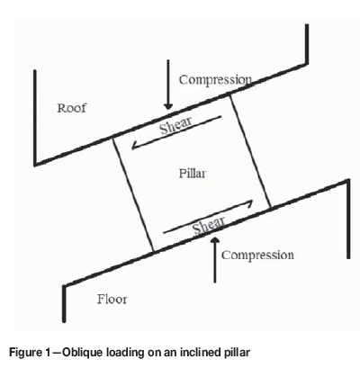
Oblique loading on pillars
Pillars dipping at an angle are subjected to oblique loading which is a combination of the compressive and shear stresses as shown in Figure 1. Pritchard and Hedley (1993) classified the pillars at Denison Mine into five categories, based on progressive failure. This investigation was conducted in an orebody dipping at 20° with the pillars showing the hourglass fracture pattern which ultimately leads to the critical cross-section area of the pillar core and ultimate failure.
Suorineni et al., (2011) noted that both pillars and excavations under oblique loading are at elevated risk of failure. This was supported by the case studies reported by Kvapil, Beaza, and Flores (1989), Hedley, Roxburgh, and Muppalaneni (1984), and Whyatt and Varley (2008). Suroineni. (2014) conducted studies to determine the failure modes of pillars with different orientations of far field principal stresses with the help of two-dimensional numerical modelling, and concluded that the most significant factors are the orientation of the far field principal stresses, width-to-height ratio, and maximum to minimum principal stress ratio.
In this paper we examine the failure modes of pillars at different pillar inclinations and determine the strength of inclined square the rectangular pillars at different width-to-height ratios.
Modelling approach
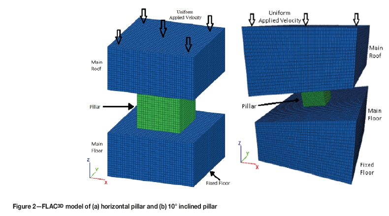
Numerical modelling provides valuable insight into the potential failure modes of the pillar if the input parameters are carefully selected and calibration is possible. FLAC3D (Itasca, 2016), a finite difference numerical modelling package, was used to simulate the horizontal and inclined pillars as the models can be calibrated to the realistic failure methodology of hard-rock pillars (Esterhuizen, 2006). A three-dimensional model was constructed to study individual horizontal and inclined pillars as shown in Figure 2.
The coordinate system used is represented by x and y axes in the horizontal plane and the z axis in the vertical plane. The main roof, pillar, and main floor are the major components of the model, as shown in Figure 2. The height of the pillar is kept constant and the width is varied to simulate the different width-to-height ratios. The extraction ratio of the horizontal pillar model was kept constant at 75% and the boundaries of the inclined pillars were far enough to avoid its influence the pillar system behaviour.
The floor was fixed such that the displacements and the velocities are restricted in the normal and parallel directions. Side boundaries were incorporated with rollers such that the displacements and the velocities were restricted only in the normal direction. A uniform velocity was applied on top of the main roof to simulate the compressional loading in the horizontal model and oblique loading in the inclined pillar model (Lorig and Cabrera, 2013).
To simulate a pillar at a depth of 300 m, the pillar was subjected to a vertical stress of about 8.1 MPa and the vertical-to-horizontal stress ratio was maintained at 1:1. The model was run to equilibrium under elastic conditions and was converted to bilinear conditions after reaching equilibrium, representing the rock mass behaviour as elastic before the excavation and as brittle and plastic after the excavation (Esterhuizen, 2006). The pillar models were then subjected to uniform velocity until complete failure. The stress-strain curves were developed to obtain the strength of the pillars with the help of a FISH function (FISH is script in FLAC3D to derive user-defined variable and functions).
The properties are critical in numerical modelling to ensure the model is realistic. The performance of the pillars is best represented by the brittle Hoek-Brown criterion (Martin, Kaiser, and McCreath, 1999; Kaiser et al., 2000; Esterhuizen, 2006). The brittle Hoek-Brown damage initiation criterion is established on the development of the brittle cracks, which generally occurs at 0.3 to 0.5 times the uniaxial compressive strength (UCS) and is followed by shear failure of the pillar. The UCS of the rock was taken to be 150 MPa, therefore the rock mass compressive strength was estimated to be about 50 MPa. Therefore, a bilinear strength envelope was used in which strength is independent of friction at low confinement and is equal to one-third of the UCS, followed by friction-hardening at the higher confinement (Kaiser, 2000).
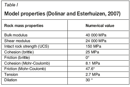
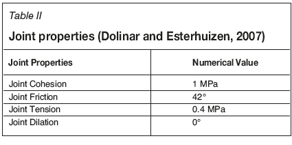
The sub ubiquitous model, an inbuilt FLAC3D program is designed to simulate the bilinear rock strength based on Mohr-Coulomb failure criterion and strain-softening as a function of deviatoric plastic strain (Itasca, 2016). The rock properties and joint properties of the model were derived with the help of the UCS and the rock mass rating (RMR) of 70, which were obtained by Dolinar and Esterhuizen (2007). The model properties are shown in the Tables I and II.
Strain-softening performance is dependent on the model element size, which is determined by using the same element size throughout all the models and calibrating the numerical model results to the theoretical results (Itasca, 2016). The model element size was kept at 0.5 m χ 0.5 m χ 0.5 m for all the models and cohesion softening was performed to calibrate the model results with the Lunder and Pakalnis (1994) results.
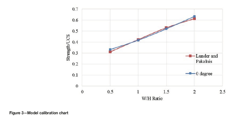
Model calibration
The models were generated at width-to-height ratios of 0.5, 1.0, 1.5, and 2.0. The modelled strength of the pillars was then compared to the theoretical results from Lunder and Pakalnis (1994) as shown in Figure 3. The difference between the model results and the theoretical results is less than 2%.
Results and discussion
Effects on strength of inclined pillar under oblique loading
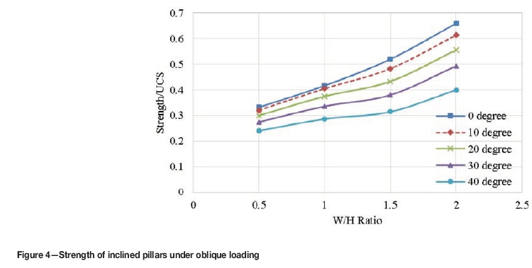
The inclined pillars experience oblique loading, which is a combination of compressive load and shear load. To evaluate the strength of the inclined pillars, the models were simulated with pillar inclinations of 0°, 10°, 20°, 30°, and 40° at varying width-to-height ratios. The results are shown in Figure 4. The pillar strength decreases with increasing pillar inclination, similar to the results presented by Suroineni et al. (2014). At lower W/H ratios, the pillar strength decreases slightly with increasing pillar inclination. At higher W/H ratios, as the pillar inclination increases, the strength of the pillar is drastically reduced compared to the pillar under pure compression.
Failure modes ofinclined pillars
The pillar failure mechanism was studied to understand the load shedding after failure of the pillars. Failure modes were derived from the model results. To understand the pillar failure modes, a section at the centre of the pillar in the direction of the y-axis (Figure 5) has been extracted and the yielded zones presented for all the pillar inclinations at different stages of loading. The failure modes of the horizontal and the inclined pillars will be presented for width-to-height ratios of 0.5 and 1.0. The horizontal pillars undergo only compressive loading while the inclined pillars undergo oblique loading, which is a combination of compressive and shear loads.
Pillar failure modes at W/H 0.5
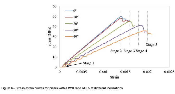
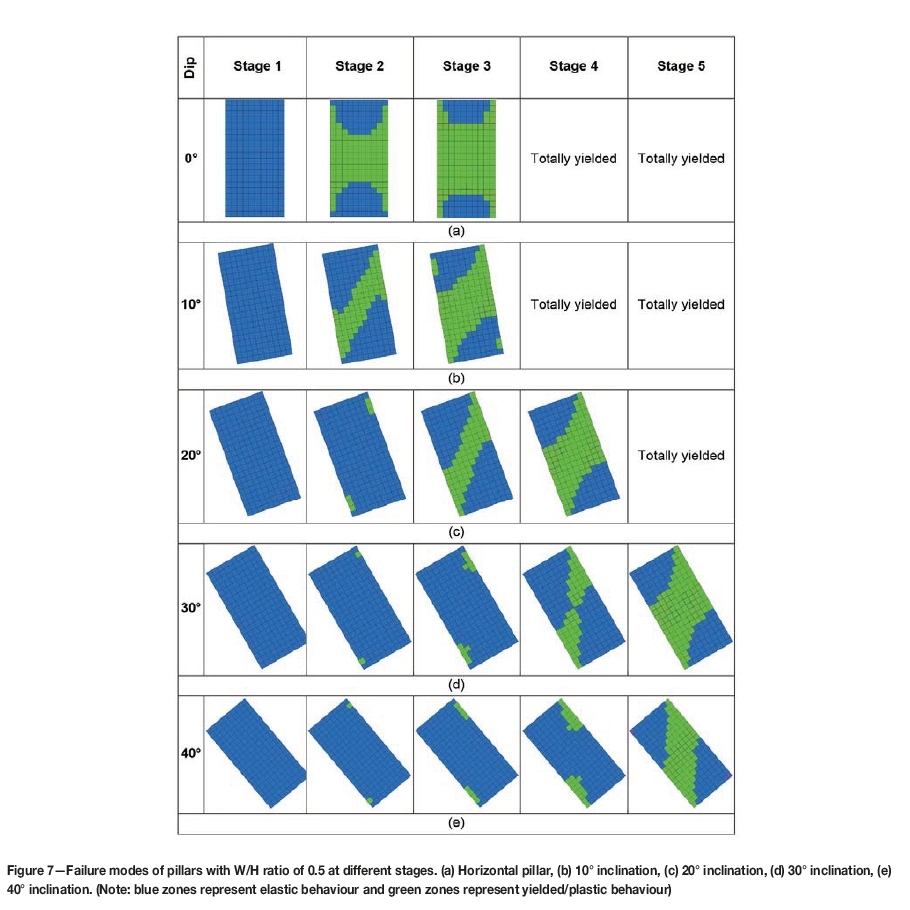
Stress-strain graphs of pillars with a W/H ratio of 0.5 at different inclinations are presented in Figure 6. At a W/H ratio of 0.5, the pillars fail by brittle spalling. This is mainly due to the absence of sufficient confinement in the pillars to mobilize the frictional component of the rock strength (Esterhuizen, 2006). The progressive failure of the pillars has been shown in five stages, which are indicated in Figure 6. The progressive failures of the horizontal and inclined pillars are shown in Figure 7. Stage 1 represents the pillar before loading. The elastic zones are highlighted in blue and the yielded zones in green.
Horizontal pillars (0° pillar) fail as the average pillar stress approaches the brittle rock strength. The brittle rock strength (50 MPa), which is one-third of the UCS (150 MPa), can be observed in the graph as the strength of the horizontal pillar. The brittle failure commences at the outer skin of the pillar and progresses towards the core at the peak stress. At stage 2, where the pillar is at its peak stress, the core has yielded, leading to total failure of the pillar as shown in Figure 7a. At stage 3, the post-peak stage of the pillar stress, the pillar has totally yielded (Esterhuizen, 2006). The final stages (stages 4 and 5) are represented as totally yielded, meaning the whole pillar is yielded (all zones are green).
For inclined pillars, stage 1 shows the pillar before loading (Figure 7). Stage 2 shows the initiation of yielding on the outer skin of the pillars in the opposite corners in the direction of the pillar inclination. Stage 2 at 10° pillar inclination shows the yielding extending towards the centre of the pillar, similar to the formation of a shear plane (Figure 7b). As yielding occurs at the centre of the pillar before total yielding of the outer skin, the strength of the pillar is reduced compared to that of the horizontal pillars.
Stage 3 of the inclined pillars shows that at lower pillar inclinations, yielding extends from the outer skin of the pillar towards the centre (Figures 7b and 7c). At higher pillar inclinations, yielding is developed only at the two corners of the pillars in the direction of pillar inclination (Figures 7d and 7e). It can be concluded that the higher the inclination of the pillar, the higher the axial strain it can sustain to attain the peak strength, which may be due to sliding at the roof and floor contacts. It can also be observed that with increasing pillar inclination, the yielding distance between the two corners of the pillar decreases, contributing to the strength reduction.
Stage 4 of the pillars at lower inclination (10° and 20° dip) shows the post-peak phase of the pillar (Figures 7b and 7c), while for the 30° pillar the yielding has extended from the outer skin to the centre of the pillar, as shown in Figure 7d. It can be observed that the 30° pillar at stage 4 is at its peak strength when the yield is approaching the centre of the pillar (Figure 6). Therefore, it can be concluded that the reduction in pillar strength with increasing inclination is a result of the loss of the core. Stage 4 of the 40° pillar shows yielding at the outer skin of the pillar (Figure 7e).
At stage 5, the pillars at inclinations less than 40° are in the post-peak phase (Figures 7b, 7c, and 7d). The yielding in the 40° pillar at stage 5 extends towards the centre, which is the point of peak strength in the pillar (Figure 7e). It can be observed that for the inclined pillars there is a rapid increase in yielding in the last stage. For example, the yielding in stage 4 of the 40° pillar is limited to the outer skin, while in stage 5 the yielding has reached the centre of the pillar.
To summarize, failure along a single plane in a brittle fashion is the dominant failure mechanism for pillars at all inclinations with W/H ratio of 0.5. Failure commences at the two pillar corners in the direction of pillar inclination and extends towards the centre of the pillar, which results in the peak strength of the pillar being reached. At higher inclinations, the pillar can sustain higher axial strains while the pillar strength is reduced. It is well-known that, for a horizontal pillar, the yielding of the outer skin is an indication that the pillar is at its peak strength (Esterhuizen, 2006); but for inclined pillars the yielding at the outer skin may not justify that conclusion.
Since the pillar core is yielded even before the complete yielding of the outer skin, it can be concluded that the failure can be violent, such as in a pillar burst. The rapid increase in the yielding of the inclined pillars from the outer skin towards the centre of the pillar is also a factor contributing towards the violent failure of inclined pillars.
Pillar failure modes at W/H 1.0
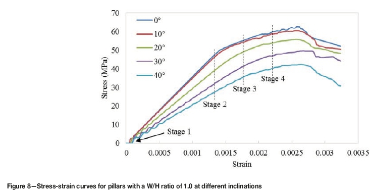
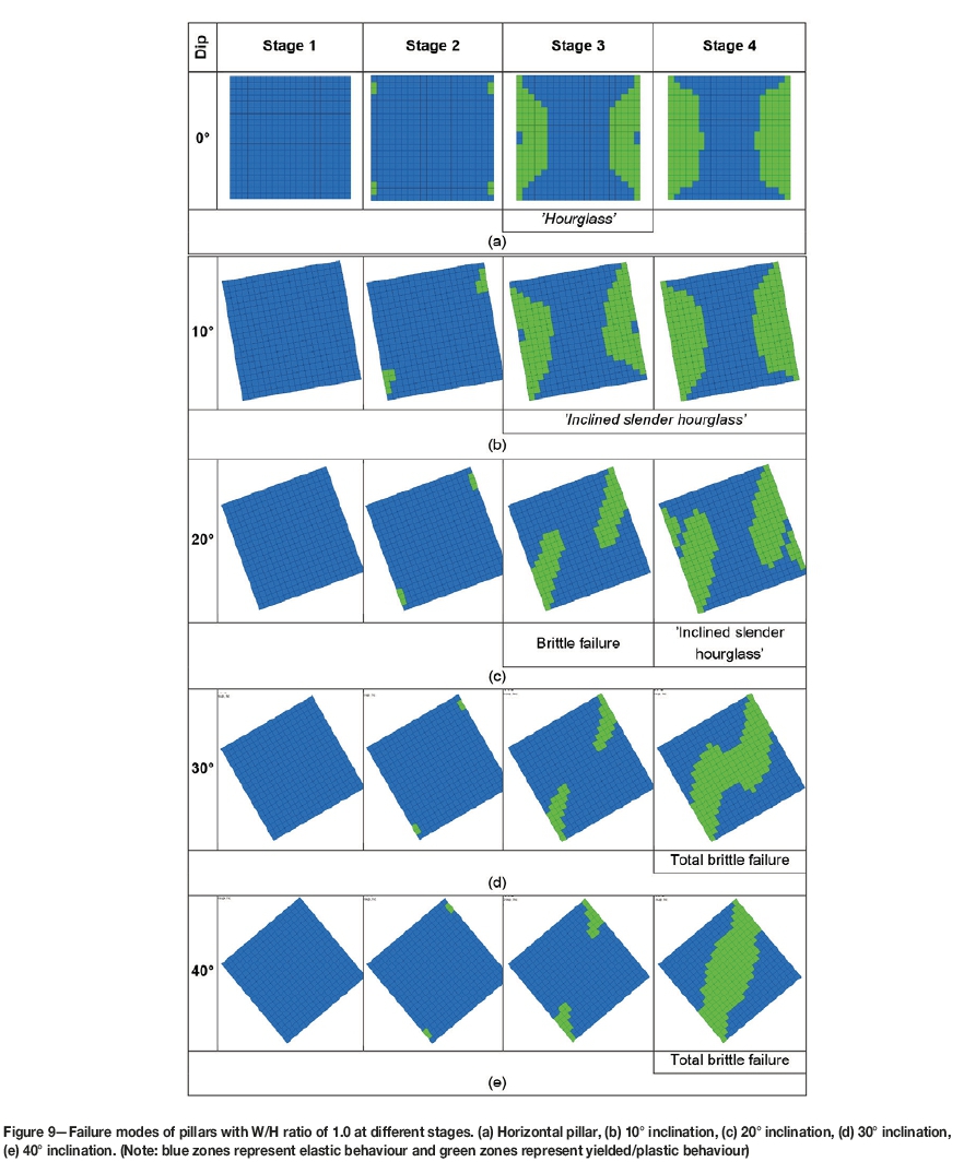
Stress-strain graphs of pillars with a W/H ratio of 1.0 at different inclinations are shown in Figure 8. The horizontal pillar fails by brittle failure at the outer skin of the pillar, followed by shear failure. The transition from brittle failure to shear failure is also observed in Figure 8, where the slope of the stress-strain curve for the horizontal pillar changes. The progressive failure of the pillars is shown in four stages, as in Figure 8. The horizontal and inclined pillar with zero initial load are shown in stage 1 of Figure 9.
In stage 1, elastic zones extend throughout the pillars as they are at zero load. Stage 2 of the horizontal (0°) pillar shows that yielding commences at the four corners of the pillar by brittle failure (Figure 9a). As the pillar load increases, the extent of brittle failure increases, followed by shear failure. Stage 3 and stage 4 show complete brittle failure at the outer skin of the pillar and shear failure starting to develop behind the brittle failure zones. The pillar stress can decrease before the core of the pillar has yielded by shear failure, similar to the results of the compression tests on small coal pillars reported by Wagner (1974).
Stage 1 of the inclined pillars shows the pillars before loading (Figure 9). Stage 2 shows that the stress on the pillar is accumulated at the two opposite corners of the pillar in the direction of inclination, due to the brittle failure (Figure 9).
Stage 3 for the 10° pillar shows complete yielding of the outer skin of the pillar due to brittle failure in the shape of an 'inclined hourglass' Figure 9b), while for the 20° pillar, the brittle failure extends from the two corners of the pillar to the interior (Figure 9c). For pillars at 30° and 40° inclination, the brittle failure extends from the outer skin towards the centre of the pillar (stage 3 in Figures 9c and 9d). Therefore, the pillars at higher inclinations can sustain more axial strain to attain the peak strength, which may be due to sliding of the pillars at the roof and floor contacts.
The extent of brittle failure in the pillars inclined at 10° and 20° is greater than in the horizontal pillar, as seen in stage 3 of Figure 9b and stage 4 of Figure 9c, which show the 'inclined slender hourglass' pattern with increasing in pillar inclination. Due to brittle failure, the depth of yielded zones has also increased in the inclined pillars. As the load increases, shear failure commences behind the brittle failure, and the outer skin of the pillar is completely transformed into a brittle failure zone. The area of shear failure decreases with increasing inclination, leading to lower strength of the inclined pillars.
At higher pillar inclinations of 30° and 40°, brittle failure extends towards the centre of the pillar, leading to core loss (stage 4 of Figures 9c and 9d). This occurs at the peak stress of the pillar. Due to this loss of confinement in the inclined pillars, shear failure is absent in the pillars inclined at 30° and 40°, leading to lower strength of these pillars. It can also be observed that the yielding at stage 4 of 30° and 40° pillars increases rapidly, which indicates that the pillars at a W/H ratio of 1.0 can also undergo violent outbursts at higher inclinations.
In summary, pillars with a W/H ratio of 1.0 at lower inclinations develop the 'inclined hourglass' pattern, which becomes slender with increasing inclination. At higher inclinations, the dominant failure mode is brittle failure which extends towards the centre of the pillar, leading to a violent outburst as the core yields even before the outer skin of the pillar. The rapid yielding of the higher inclination pillars due to brittle failure may also be a basis for violent outbursts.
The pillar failure mechanism of 20° inclined models is similar to the behaviour observed in the Dension Mine (Pritchard and Hedley, 1993). Minor spalling at the ends of the pillars can be observed in the models (stage 3 of Figure 9c) as well as in Figure 10. This then progresses to strong sidewall spalling, which resembles stage 4 of Figure 9d. Therefore, it can be concluded that pillars at other inclinations would show a similar failure mechanism in situ, as shown in Figures 9 and 11.
Failure mechanism in pillars with W/H ratio greater than 1
The failure mode changed from complete brittle failure at a W/H ratio of 0.5 to partial brittle failure plus shear failure at a W/H ratio of 1.0. This transformation was observed for 0°, 10°, and 20° pillars, while the 30° and 40° inclined pillars were observed to undergo total brittle failure. A similar transformation will be observed at higher inclinations with an increase in W/H ratio. Therefore, it can be concluded that the at higher W/H ratios, the failure mode of the pillars will be partial brittle failure in combination with shear failure, as indiated in Figure 11.
The 'inclined hourglass' pattern in the inclined pillars, which becomes slender with increasing inclination, can be attributed to the decrease in the strength of the inclined pillars at a W/H ratio of 1.0. It can be concluded that similar behaviour will be observed at higher W/H ratios.
Rectangular pillars
Models were simulated to investigate the effects of inclination on rectangular pillars. The inclined rectangular pillars can be classified into dip and strike pillars. For the strike pillars, the length of the pillar was increased perpendicular to the direction of inclination (Figure 12a), while for the dip pillars, the length was increased parallel to the inclination (Figure 12b). The three width to height ratios of 0.5, 1.0, and 1.5 and length to width ratios of 1.0, 2.0, and 3.0 at varying pillar inclinations were simulated.
For the horizontal pillars, the rectangularity in dip is equal to the strike. The pillars with W/H ratios of 0.5 and different L/W ratios have similar strengths as the failure mechanism is dominated by brittle failure. At W/H ratios of 1.0 and 1.5, the pillar strength increases with increasing L/W ratio, as shown in Figure 13. This is due to the fact that at higher W/H ratios, shear is the dominant failure mechanism and with the increase in length, a large shear failure area is formed which results in an increase in pillar strength. It can be concluded that pillar strength increases with increasing L/W ratio at higher W/H ratios. The model results are similar to the results of Dolinar and Esterhuizen (2007).
Inclined rectangular pillars
The rectangular pillars at 10°, 20°, 30°, and 40° inclinations along the strike and dip were simulated to determine the strength. Fifteen models each for different inclinations were modelled: three with W/H ratios of 0.5, 1.0, and 1.5 and L/W ratio of 1.0 to represent the square pillars, and six models each with W/H ratios of 0.5, 1.0, and 1.5 and L/W ratios of 2.0 and 3.0 along both strike and dip.
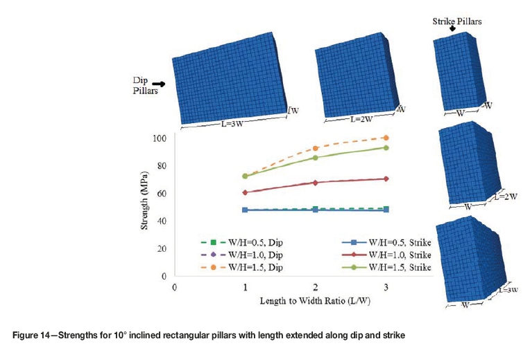
At 10° inclination, the strength of the pillar increases with increasing pillar length at higher W/H ratios, but remains the same at a W/H ratio of 0.5. The pillars with lower W/H ratios show no difference in strength between the dip and strike pillars (Figure 14), similar to the horizontal pillars (Figure 13). At a higher W/H ratio of 1.5, the dip pillars have a 7% higher strength than the strike pillars, as shown in Figure 14.
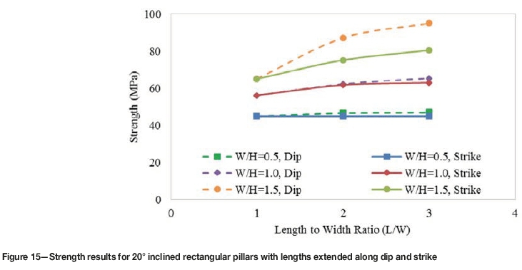
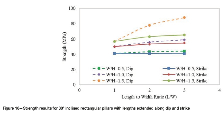
At inclinations of 20° and 30°, the strength of the pillars increases with increasing length along dip at any W/H ratio.
It can also be observed that the rectangular pillars with length extended along strike show minimal to no increase in strength compared to square pillars (Figure 15 and 16). At a W/H ratio of 1.5, the strengths of the rectangular dip pillars are 14% and 20% greater than the corresponding rectangular strike pillars, respectively. Therefore, it can be concluded that rectangular pillars are beneficial only when the longer axis is along dip and the W/H ratio greater than or equal to 1.5.
At 40° inclination, it can be observed that the strike pillars show no increase in strength with an extension of length at any W/H ratio (Figure 17). This means that the square pillar with W/H ratio of 1.5 and the rectangular pillar with W/H ratio of 1.5 and L/W ratio of 3 along the strike have equal strengths. This fact can be used for determining the strength of the sill pillars.
Sill pillars are inclined and considered to be infinite in length and are modelled in a two-dimensional framework. A simple approximation for the strength of the sill pillars can be made by calculating the strength of a square pillar at that inclination and W/H ratio. This holds true as the length is not contributing towards the increase in pillar strength.
Conclusions
Based on the modelling undertaken, the effects of dip on pillar strength can be summarized as follows.
► The pillar strength is relatively low at higher inclinations compared to horizontal pillars. Therefore, higher safety factors are required while designing inclined pillars with the traditional approaches.
► Brittle failure is the dominant failure mechanism in the inclined pillars. The initiation of the pillar deformation is sluggish, but the pillar yields rapidly when it reaches its peak stress.
► Violent outbursts can be expected in the inclined pillars due to core loss, even before the deformation in the outer skin of the pillar, and also due to the rapid deformation near the peak pillar stress.
► Rectangular pillars are beneficial only with W/H ratios greater than 1.5 and when the length of the pillars is increased along the dip at higher inclinations.
► The strength of the sill pillars can be approximated using the results for square pillars, as inclined pillars with increased length in the strike direction show minimal to no increase in strength compared to square pillar.
References
Dolinar D.R. and Esterhuizen G.S. 2007. Evaluation of the effects of length on strength of slender pillars in limestone mines using numerical modelling. Proceedings of the 26th International Conference on Ground Control in Mining, Morgantown, WV. West Virginia University. pp. 304-313. [ Links ]
Esterhuizen G.S. 2006. An evaluation of the strength of slender pillars. Transactions of the Societyfor Mining, Metallurgy, and Exploration, vol. 320. pp. 69-76. [ Links ]
Esterhuizen G.S., Dolinar D.R., and Ellenberger J.L. 2008. Pillar strength and design methodology for stone mines. Proceedings of the 27th International Conference on Ground Control in Mining, Morgantown, WV. West Virginia University. pp. 241-253. [ Links ]
Galvin J.M., Hebblewhite B.K., and Salamon M.D.G. 1999. Coal pillar strength determinations for Australian and South African mining conditions. Proceedings of the Second International Workshop on Coal Pillar Mechanics and Design, Vail, CO, 6 June 1999 NIOSH, Pittsburgh, PA. pp. 63-71. [ Links ]
Hedley, D.G.F., Roxburgh, J.W., and Muppalaneni, S.N. 1984. A case history of rockbursts at Elliot Lake. Proceedings of the Second International Conference on Stability in Underground Mining. Brawner, C.O. (ed.). American Institute of Mining, Metallurgical and Petroleum Engineers Inc., New York. pp. 210-234, [ Links ]
Hedley, D.G.F. and Grant, F. 1972. Stope and pillar design for the Elliot lake uranium mines. CIM Bulletin, vol. 65. pp. 37-44. [ Links ]
Itasca Consulting Group, 2016. Fast Lagrangian analysis of continua in 3 dimensions. Minneapolis, MN, USA. [ Links ]
Kaiser, P.K., Diederichs, M.S., Martin, C.D., Sharp, J., and Steiner, W. 2000. Underground works in hard rock tunnelling and mining. Proceedings of GeoEng2000. ICMS, Melbourne. pp. 841-926, [ Links ]
Kaiser, P.K., Kim, B., Bewick, R.P., and Valley, B. 2011. Rock mass strength at depth and implications for pillar design. Transactions of the Institution of Mining and Metallurgy. Section A: Mining Technology, vol. 120, no. 3. pp. 170-179. [ Links ]
Kvapil, R.L., Beaza, J.R., and Flores, G. 1989. Block caving at EI Teniente mine, Chile. Transactions of the Institution of Mining and Metallurgy. Section A: Mining Technology, vol. 98, no. 6. pp. A43-A56. [ Links ]
Lorig, L.J. and Cabrera, A. 2013. Pillar strength estimates for foliated and inclined pillars in schistose material. Proceedings of the 3rd International FLAC/DEM Symposium, Hangzhou, China, October 2013. Zhu, H. et al. (eds). Itasca International Inc., Minneapolis, MN. Paper 01-01 [ Links ]
Lunder, P.J., and Pakalnis, R. 1997. Determining the strength of hard rock mine pillars. CIM Bulletin, vol. 90. pp. 51-55. [ Links ]
Mark, C. and Chase, F.E. 1997. Analysis of retreat mining pillar stability (ARMPS). Proceedings of the Seminar on New Technology for Ground Control in Retreat Mining, Pittsburgh. US Bureau of Mines. pp. 17-34 [ Links ]
Martin, C.D., Kaiser, P.K., and McCreath, D.R. 1999. Hoek-Brown parameters for predicting the depth of brittle failure around tunnels. Canadian Geotechnical Journal, vol. 36, no. 1. pp. 136-151. [ Links ]
Martin, C.D. and Maybee, W.G. 2000. The strength of hard rock pillars. International Journal of Rock Mechanics and Mining Sciences, vol. 37. pp. 1239-1246. [ Links ]
Pritchard, C.J. and Hedley, D.G.F. 1993. Progressive pillar failure and rockbursting at Denison Mine. Rockbursts and Seismicity in Mines: Proceedings of the 3rd International Symposium, Kingston, Ontario, 16-18 August 1993. Young, R.P. (ed.). Balkema, Rotterdam. [ Links ]
Suorineni, F.T., Mgumbwa, J.J., Kaiser, P.K., and Thibodeau, D. 2011. Mining of orebodies under shear loading. Part 1 - case histories. Transactions of the Institution of Mining and Metallurgy. Section A: Mining Technology, vol. 120, no. 3. pp. 138-147. [ Links ]
Suorineni, F.T., Mgumbwa, J.J., Kaiser, P.K., and Thibodeau, D. 2014. Mining of orebodies under shear loading. Part 2 - failure modes and mechanisms. Transactions of the Institution of Mining and Metallurgy. Section A: Mining Technology, vol. 123, no. 4. pp. 240-249. [ Links ]
Wagner, H. 1974. Determination of the complete load-deformation characteristics of coal pillars. Proceedings of the 3rd Congress of the International Society for Rock Mechanics. Denver, CO. Part B. pp. 1067-1081. [ Links ]
Wagner, H. 1992. Pillar design in South African collieries. Proceedings of the Workshop on Coal Pillar Mechanics and Design. IC 9315. US Bureau of Mines. pp. 283-301. [ Links ]
Whyatt, J. and Varley, F. 2008. Catastrophic failures of underground evaporite mines. Proceedings of the Twenty-Seventh International Conference on Ground Control in Mining, Morgantown, WV. West Virginia University. pp. 113-122. [ Links ] ♦
Paper received May 2017
revised paper received Sept. 2017

