


Services on Demand
Article
 English (pdf)
 Article in xml format
 Article references
Indicators

Related links
-
 Cited by Google
 -
 Similars in Google
Share

 Permalink
Journal of the Southern African Institute of Mining and Metallurgy
On-line version ISSN 2411-9717
Print version ISSN 2225-6253
J. S. Afr. Inst. Min. Metall. vol.118 n.7 Johannesburg Jul. 2018
http://dx.doi.org/10.17159/2411-9717/2018/v118n7a8
PAPERS OF GENERAL INTEREST
Interaction between vertical stress distribution within the goaf and surrounding rock mass in longwall panel systems
P. WangI; J. ZhaoII, III; G. FengI, IV; Z. WangII
ICollege of Mining Engineering, Taiyuan University of Technology, China
IICollege of Resource and Safety Engineering, China University of Mining and Technology Beijing, China
IIIRussian Academy of Natural Sciences, Russia
IVShanxi Engineering Research Center for Green Mining, China
SYNOPSIS
Four main longwall panel systems are used in China: conventional longwall top coal caving (CLTCC), multi-slice longwall mining (MLM), high-seam longwall mining (HSLM), and longwall mining with split-level gateroads (LMSG). Theoretical analyses and physical modelling studies were carried out to investigate the interaction between vertical stress distribution within the goaf and surrounding rock mass in these systems. These studies were supported by numerical analyses and validated by field observation. The difficulty in numerical analysis for longwalls lies in goaf modelling, and research on this is rare. Reasonableness and correctness of numerical modelling is highly dependent on goaf behaviour. A complete and detailed numerical model of stress distribution within the goaf and surrounding rock mass is presented in this paper. A double-yield constitutive model, which is best fitted by Salamon's model that was obtained through laboratory tests, is used to simulate the goaf. The angle of break obtained through physical modelling was also incorporated into numerical modelling, which is closer to practice. The modelling shows that: (1) the more load the goaf bears, the less the abutment pressure and vice versa; (2) the abutment pressure, stress concentration factor, and yield zones would be larger without considering goaf behaviour; (3) goaf pressures in the curved section employing HSLM and LMSG are larger than in MLM and CLTCC; (4) when one slice is being extracted in MLM, the goaf pressure is greater than with any other methods, and the high-stress zone and yield zone are smaller; (5) the goaf edge is the most destressed zone in the entire panel system of the four mining methods. Field observation shows that the intake entry in LMSG has a favorable stress environment. Ground control problems such as severe deformation and bursts in the entry are therefore minimized, which in turn validates the theoretical and modelling analyses.
Keywords: longwall mining, stress distribution, goaf behaviour, numerical modelling, double yield, abutment pressure, surrounding rock mass, split-level.
Introduction
Longwall mining is the main underground coal mining method in China. Since China's coal reserves occur in a variety of geological environments (thick or ultra-thick coal seams (more than 3.5 m), steeply inclined seams, deep cover, etc.), many longwall panel systems, including multi-slice longwall mining (MLM), high-seam longwall mining (HSLM), conventional longwall top coal caving (CLTCC), and longwall mining with split-level gateroads (LMSG) have been developed (Du and Meng, 2009). Ground pressure resulting from coal extraction is a dominant factor in any failure of a panel. Therefore, determining the stress state of a panel system is crucial for safe production (Wang et al., 2017; Zhao, Hebblewhite, and Galvin, 2000).
Zhenchengdi coal mine is located in Xishan mining area, Shanxi Province, China. A simple mono-synclinal structure is the major tectonic structure. Number 2-4 coal seam is the main seam, with an average dip angle of 4° and cover depth of 230 m. No. 22202 and 22204 panels are 680 m long along the strike and 130 m wide along the dip. The coal seam is 4.5-5.8 m thick, with a low gas content. The roof strata comprise fine-grained sandstone (2.2 m) followed by sandy mudstone (6.4 m), while the floor strata are muddy sandstone (3.1 m) underlain by siltstone (4.2 m). Four longwall panel systems as mentioned above were designed for the mine, and the corresponding panel layouts are shown in Figure 1.

For CLTCC (Figure 1a), the lower section of the seam is cut by the shearer at a set height, and the coal left above the section cut by the machine is induced to cave into the rear conveyor, taking advantage of the fracturing due to the front abutment pressure. MLM (Figure 1b) divides the coal seam into two slices, with each slice longwall-mined sequentially. The upper slice is generally mined first in order to maintain the integrity of the lower slice. HSLM (Figure 1c) involves cutting the whole bed by one web. In LMSG (Figure 1d) gateroads on either end of the panel are located at different elevations in the coal seam, one along the floor and the other along the roof (Zhao, Wang, and Su, 2017; Zhao, 1998). During the last two decades, the mine used HSLM and MLM. However, due to the varied height of the coal seam, the HSLM shields could not accommodate the geological conditions and MLM could not achieve high production and high efficiency. Market competition and geological conditions pushed the mine to use CLTCC a few years after HSLM and MLM. Then LMSG was introduced about 8 years ago, resulting in a large increase in profit.
However, there are still many problems with CLTCC. The first is low recovery, because a relatively large gateroad pillar is left unmined between two adjacent panels and the top coal above the 4-5 end shields and the two gateroads is not recoverable using CLTCC. This becomes loose coal, which increases the risk of spontaneous combustion. Furthermore, ground control problems are severe in the gateroad close to the goaf as a result of the side abutment pressure acting on the gateroad pillar. In the past, coal bumps, rib sloughing, and slabbing frequently occurred within the development entry next to the goaf, which 'parked' or idled the longwall and caused tremendous production losses. The engineers concluded that the problems were caused by the stress concentration on the gateroad pillar. This remains a difficult problem to solve. On one hand, leaving a large pillar results in low recovery, which is critical owing to the dwindling coal reserve; on the other hand, a small pillar leads to instability and many ground control difficulties. In addition, for the abovementioned four mining methods that the mine has used, the severity of the ground control problems within the development entry next to the goaf vary, which baffled the engineers. It is certain that the behaviour of ground pressure relates to the mining methods, as this was corroborated by the historical records of longwall panels that have used the four systems in the past in this mining district. Ground control problems are similar for longwall panels employing the same system under the similar geological conditions.
A stope is an integrated system, and every sub-system interacts. It is known that after extraction of a longwall panel the pre-mining stress is redistributed and the overlying strata are disturbed with decreasing severity from the immediate roof towards the surface (Qian Shi, and Xu, 2010; Peng, 1978). Failure of the roof may continue even after the higher strata and caved material are in contact. The compaction of the caved material increases until a new equilibrium is reached, when no additional strata subsidence occurs and the goaf sustains a certain amount of overburden load from the overlying strata (Peng, 1978). For the surrounding rock mass around the goaf, abutment pressure is developed. The next panel is developed a sufficient distance from the over-stressed area and a coal pillar is left unmined between the adjacent panels. Thus the coal pillar is used to sustain the side abutment pressure and maintain the stability of the development gateroad(s) of the active panel.
Wilson (1981) presented an approach for calculating the depth of the plastic zone of a coal pillar. Yavuz (2004) proposed a method for estimation of the cover pressure distance and the pressure distribution in the goaf of flat-lying longwall panels. Morsy and Peng (2002) studied the goaf loading mechanism in longwall coal mines using numerical modelling. Campoli et al., 1993) studied goaf and gateroad reaction to longwall mining in bump-prone strata. Esterhuizen, Mark, and Murphy (2010) calibrated a numerical model for simulation of coal pillars, and the goaf and overburden response. However, the relationship between the goaf behaviour and the surrounding rock mass is still not well understood, especially as regards the different mechanisms behind these different mining methods. In view of the fact that studies of the interaction between goaf behaviour and surrounding rock mass in these longwall mining systems are rare, in this paper we present such a study based on theoretical analysis, physical modelling, numerical modelling, and field observation.
Theoretical analysis
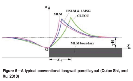
The goaf and surrounding rock mass have a strong interconnectivity. Before the excavation of a longwall panel, pre-mining stress is uniformly distributed. After excavation the stress redistribution results in side abutment pressure and goaf pressure that increases from zero at the goaf edge to the pre-mining stress at a certain distance from the goaf edge, as shown in Figure 2. The stress on the solid coal on the right can be divided into four zones: I - destressed yield zone, II - overstressed plastic zone, III - overstressed elastic zone, and IV - pre-mining vertical stress zone. The limit equilibrium zone x0ranges from 3 to 20 m in width and is typically between 5 and 12 m, and can be calculated by (Quian Shi, and Xu, 2010):


where m is the mining height,/ is the friction factor between the coal seam and roof and floor strata, φ is the angle of internal friction of the coal mass, C is the cohesion, y is the unit weight, H is the cover depth, k is the stress concentration factor, p1is the external support force (steel sets, pipe-shed support, or other type of support) acting on the rib, and 
The stress redistribution discussed above is an example of the interaction between the goaf and surrounding rock mass. Obviously, this interaction is influenced by many factors such as panel geometry, mining height, and cover depth, because the integral of the vertical stress after excavation plus the stress of extracted coal must equal the integral of the vertical stress before excavation. Thus, the more load the goaf bears, the lower the abutment pressure, and vice versa. Therefore, the load borne by the goaf must have an influence on stress concentration factor k. On the other hand, the load-bearing characteristics of goaf are related to goaf configuration, which is determined by the panel layout or geometry, for different panel layouts lead to different modes of roof strata failure, fracturing, subsidence, and movement, thus influencing goaf configurations. Figure 3 depicts the strata movement and goaf configurations for the different panel configurations in the four longwall mining methods shown in Figure 1.
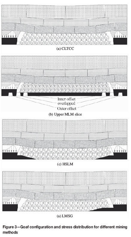
Esterhuizen, Mark, and Murphy (2010) indicate that fall height, size, and shape of the rock fragments affect the bulking of the goaf, as shown in Figure 4. The greater the fall height, the more likely it is that the fragments will rotate and come to rest in a jumble. For the subsequent falls, fall height is reduced, thus the fragments will be arranged in a more orderly fashion and the amount of bulking will be reduced. Therefore, the greater the mining height, the less the compaction of the goaf, resulting in a smaller goaf pressure. According to the vertical stress integral analysis presented earlier, the pressure deficiency in the goaf will be borne by the abutment pressure.

As a result, for CLTCC (Figure 3a), the symmetrical panel geometry leads to a symmetrical abutment pressure distribution.
For MLM (Figure 3b), when mining the upper slice, the mining height reduces to half of the total seam thickness, which means that m in Equation [1] becomes m/2, hence the limit equilibrium zone x0 is only half of that in CLTCC. What's more, as the stress concentration factor k also drops due to the decrease in mining height, x0 would consequently be less than m/2. On the other hand, rock fragments are more orderly arranged and the goaf accepts more load from overlying strata, leading to a lower side abutment pressure.
There are three main roadway layouts for the lower slice - inner offset, overlapped, and outer offset, as shown in Figure 3b. Inner offset gateroads of the lower slice are located under the stabilized goaf of the upper slice, which is in a destressed state (Peng, 2006). The mine planned to use inner offset gateroads for the lower slice in order to reduce the pressure on gateroads and the support cost. The original support design was steel yieldable I-beam sets together with mesh during extraction of the upper slice. The drawbacks of MLM are the low recovery due to the coal remaining in the pillar and repeated disturbance of the goaf, which increases the risk of spontaneous combustion.
For HSLM (Figure 3c), there is a curved section on either end of the goaf where the mining height decreases. This leads to localized higher goaf pressure within the sections compared with CLTCC. For the remainder of the goaf, the pressure is similar to that in CLTCC. Since the load borne by two ends of the goaf increases, the abutment pressure is less than that in CLTCC, but higher than that when mining the upper slice in MLM.
For LMSG, as only one end of the panel has an elevating section, the pressure distribution for the two ends of the panel is different: the goaf pressure at the curved section is larger than that of the other side, and while the abutment pressure on the left side is similar to that in CLTCC, that on the other side is similar to HSLM, as shown in Figure 3d.
According to the analysis above, the corresponding theoretical stress distribution for four mining methods is given below.
Physical modelling
In physical modelling, the goaf pile configuration and roof strata break or subsidence can be displayed visually. Strata movement can be measured by photogrammetry. Strain gauge indicators and stress sensors are used to collect stress-strain data. The accuracy of physical modelling has been improved in the past two decades by external observation and measurement methods including optical measurement, digital image correlation (DIC), photogrammetry, etc. (Ghabraie etal, 2015; Weishen et al., 2011).
In this investigation, physical modelling was used to observe the strata movement characteristics and goaf development process. Due to the limitation of the experimental period, only two experiments were carried out, one on CLTCC and the other on LMSG. Two large-scale physical models, using plane-stress simulation, were developed. The model dimensions were length 162 cm, height 130 cm, and thickness 16 cm (Figure 6). A strain gauge indicator was installed along the floor to monitor the stress. For physical model development, a geometric scaling factor Cl (the ratio of model size to prototype size) of 1:100, and density factor Cp (the ratio of model density to prototype density) 1:1.5 were used (Weishen et al., 2011). Key steps and results are shown in Figure 7.

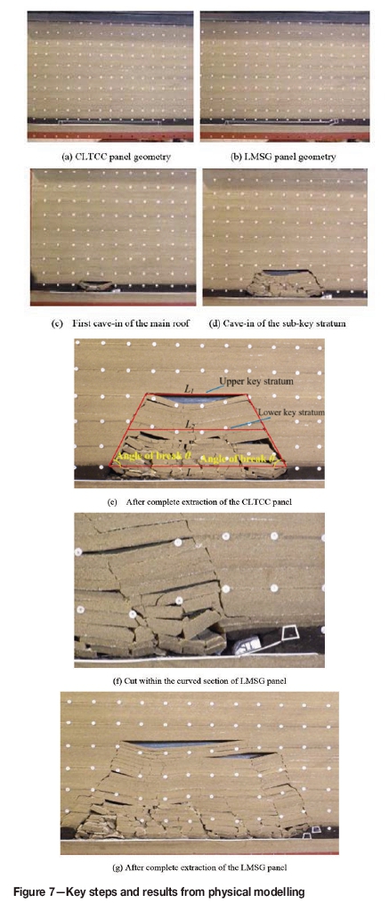
From Figure 7 we can see, firstly, that the clutter of the arrangement of the caved rocks reduces in ascending order. In addition, the caved rocks on the right end of the LMSG panel are in better order than that on the left end (Figure 7g). Physical modelling indicates the basic goaf development configurations. But note that physical modelling cannot represent the in situ situation perfectly. For instance, the sizes of the caved rocks (especially those from immediate roof) are much larger than those in reality.
Secondly, caving lines are developed on two sides of the panel with the cave-in process of the overlying strata as shown in Figure 7(e). The angle of break is defined as the acute angle formed by the caving line and coal seam bedding plane. Thus, according to the geometrical relationship and key stratum theory (Qian, Shi, and Xu, 2010), the span L2of the lower key stratum surpasses its limit caving interval and caves in, while the uppermost key stratum does not fracture, meaning that span L1 is at less than its limit caving interval. Therefore, angle of break has a significant influence on the fracturing and caving of overlying strata. For a panel with a certain width, after extraction of the panel, the larger the angle of break, the easier the fracture of an overlying stratum, and then the load of the caved stratum is borne by the goaf. On the other hand, if the angle of break is relatively large, the span of an overlying stratum cannot reach the limit caving interval, and then the load would transfer to the abutment due to its overhang above the goaf. It is evident that angle of break has a significant influence on stress distribution after the extraction of a panel, for both the goaf and the abutment, which would also affect numerical modelling. Most of the numerical modelling exercises to date have not incorporated the angle of break or have used an angle of break of 90°, which is not reasonable. The angles of break in physical modelling were obtained by using photogrammetry and were incorporated into the subsequent numerical modelling. The angles of break on the left and right in CLTCC are 60.9° and 58.7°, respectively. The angles of break on the left and right in LMSG are 59.6° and 62.7°, respectively. An angle of 60° was used in the numerical modelling so as to reduce the difficulty in establishing models.
Stress-strain data is translated into stress data and is shown in Figure 8. As a conventional rectangular pillar is eliminated by employing LMSG, the panel width is 10 m larger than that in CLTCC (Figure 1), thus the span of overlying strata in LMSG is greater than that in CLTCC, leading to the fracturing of higher strata. From the left end to the middle, the goaf pressures of the two methods are almost the same. On the right of the goaf, due to the curved section, the goaf pressure (red curve) is higher when x = 135 m, which point locates on the right at the curved section. When x = 145 m, i.e. the goaf edge, the goaf pressure is near zero. In addition, the average goaf pressure in LMSG is slightly greater than in CLTCC, as a result of the increase in the panel width due to the elimination of the rectangular pillar in CLTCC, and the amount of the caved rocks is greater. As more pressure is transferred to the goaf, the corresponding abutment pressure is smaller than that in CLTCC, as can be seen in Figure 8.

Numerical modelling
The Mohr-Coulomb constitutive model is used for the rock strata modelling, and the double-yield constitutive model for the goaf modelling. The key to the success and practicality of numerical analysis for longwalls is goaf modelling, which is difficult due to the unavailability of goaf material parameters and difficulties in determining proper constitutive models. Very few studies have been conducted on goaf material. Pappas and Mark, (1993) studied the compaction characteristics of goaf material through laboratory tests, and indicated that Salamon's model agrees well with the laboratory results. Salamon's model (Salamon, 1990) is:

where σ is the uniaxial stress applied to the material (MPa), ε is the strain occurring under the applied stress, E0is the initial tangent modulus (MPa), and emis the maximum possible strain of the bulked rock material.
Yavuz (2001) carried out a study on the goaf pressure re-establishment, which also involves goaf behaviour, and derived the following relationship:

where ocis the compressive strength of the rock pieces within the goaf, [MPa].em is related to the initial bulking factor b of goaf material (Peng, 1978):

The initial bulking factor b is given as:
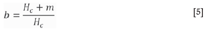
where Hcis the height of the caved zone (m).
With the development of the finite-difference program FLAC3D, the built-in double-yield constitutive modelling capability can be used to simulate the goaf behaviour, as the double-yield constitutive model represents a material in which there may be significant irreversible compaction in addition to shear yielding, such as hydraulically placed backfill or lightly cemented granular material (Itasca, 2012).
It is evident that in the initial stage of the numerical modelling, the goaf cannot bear the weight of the overlying strata, which fracture and subside, and this in turn gradually compacts the goaf, leading to the increase in the volumetric strain. The stress and volumetric strain are related as proposed by Salamon (Equation [2]). When the pressure borne by the goaf increases to a point when overlying strata do not subside further, a new equilibrium is reached and stress is redistributed both in the goaf and the surrounding rock mass. A reasonable numerical model is expected to demonstrate the above process.
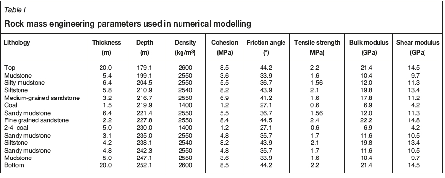
The numerical models were built based on Figure 1. For convenience of comparison, a model in which the goaf was assigned as null was also built. All the models were 400 m long, 90.8 m high, and 300 m thick. The LMSG model is shown in Figure 9. A vertical pressure of 79.1 m χ 0.027 MN/m3 (4.84 MPa) was applied on the top of the model to simulate the overburden weight. The horizontal sides were roller-constrained and the bottom boundary was fixed both horizontally and vertically. The horizontal-to-vertical stress ratio was set to be 1.2 in the x andy directions according to in situ data. A bedding plane was simulated by inserting interfaces between different strata using the same parameters as in the literature (Wang, Wang, and Yang, 2017). Rock mass engineering parameters are given in Table I. Now the key is to determine the properties for the goaf.

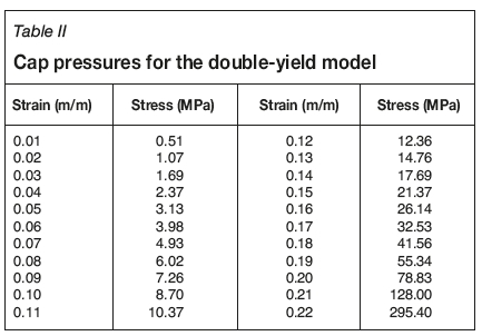
According to the engineering data for the 22202 panel, the height of the caved zone is about 16.9 m above the coal seam, according to observations in the goaf gas boreholes which reach to the 5.8 m thick siltstone stratum. Hence, the bulking factor was calculated to be b = 1.3 and the maximum strain of the goaf was calculated as em= 0.23 m/m. Taking oc = 30 MPa (Yavuz, 2004; Pappas and Mark, 1993), the initial goaf modulus was E0= 48.9 MPa. Cap pressures for the double-yield model are shown in Table II and are expressed by:
In order to obtain the parameters for the goaf and make sure that the strain-stress relationship satisfies Equation [6], a simple model with dimensions 1 m (length) χ 1 m (width) χ 2 m (height) was built. Loading was simulated by applying a velocity on the top surface with the bottom surface and four side surfaces fixed. The input parameters were fitted by an iterative change in the bulk and shear moduli, the angle of dilation, the angle of friction, and the density of the goaf material. By trial and error, the final properties in Table III were arrived at. The volumetric strain, vertical stress contours, and stress-strain matching curves of the two methods are shown in Figure 10. The numerical modelling results for CLTCC are shown in Figure 11.


From Figure 11 it is clear that the stress concentration areas are developed within the surrounding rock mass on two sides of the goaf. Within these zones, the upper strata are subjected to higher stress concentration than the lower strata, which shows the effect of the goaf on spatial abutment pressure distribution. The simulated floor stress monitoring results are shown in Figure 11e. Goaf pressure increases gradually from zero at the goaf edge and peaks in the middle of the goaf. It can be seen that the failure develops in the same direction as the caving line in tensile and shear failure modes; the middle of the overlying strata above the goaf shows tensile failure (three red ellipses in Figure 11c). This demonstrates that the middle of the overlying strata above the caved zone and close to the caving line undergoes tensile failure, resulting in corresponding destressed zones around them (the three ellipses in Figure 11a). Failure development within the floor strata is also along the direction of the caving line. The area of the yield zone within the coal seam increases from top to bottom.
In order to show the reasonableness of considering the goaf, numerical modelling ignoring the goaf was also carried ou.t. The results are shown in Figure 12.

During the running of FLAC3D, if the goaf is not taken into account, i.e., a null is assigned to the goaf, the maximum unbalanced force cannot reach the default value of 1 χ 10-5, remaining around 4.4 χ 10-4, which means the equilibrium results are not ideal. Figure 12 shows that although the roof subsides somewhat, it still overhangs the 130 m wide extracted area. Thus the roof is in a tensile state, which is not realistic. In reality, the roof strata will subside and touch the goaf, hence there would also be compressive stress; the concentrated stress appears mainly within the abutment of the coal seam and the two rock strata overlying the seam. Compared with numerical modelling results incorporating the goaf effect, the following differences are apparent:
► The stress concentrated abutment pressure zone (dark blue zones in Figure 12b) is lower
► The height of the zone decreases
► The stress concentration factor is larger, and the zone traverses the coal seam
► The areas of floor and roof failure and the yield zone are larger
► The surface subsidence is larger
► The floor stress monitoring indicates that the floor stress is zero, which is totally unreasonable.
Most importantly, as there is no goaf material in Figure 12, the support force against the overlying strata is zero, which leads to higher abutment pressure. From Figure 12d, the abutment pressure peak is 22.5 MPa, thus the stress concentration factor is 22.5 τ 6.2 = 3.63; while for modelling with goaf material, abutment pressure peak is 21.8 MPa, and stress concentration factor is 20.0 τ 6.2 = 3.23. It is evident that the effect of the goaf cannot be ignored, or unreasonable modelling results would ensue. The modelling results for LMSG are shown in Figure 13.

Figure 13 shows that failure of the overlying strata develops in the same direction as the caving line in tensile and shear failure modes. Tensile failure (green elements) occurs in the middle of the overlying strata, which demonstrates that the middle of the strata overlying the caved zone and close to the caving line undergoes tensile failure, resulting in corresponding destressed zones around these areas. The curved section is located in the destressed zone under the caving line. Meanwhile, the yield zone around the curved section is smaller and the integrity of the coal mass is better. Therefore, the gateroads located here would suffer lower ground pressure and ground control problems would be consequently be minimum. According to records for several panels in Zhenchengdi coal mine, dynamic disasters such as rockbursts or coal and gas outbursts have never occurred under such conditions.
The stress monitoring results (Figure 13e) indicate that the abutment pressure on the side of the curved section is smaller and the goaf pressure increases faster. This means that the load borne by the goaf is larger, especially for the curved section (red circle in Figure 13e). The modelling results for HSLM are shown in Figure 14.
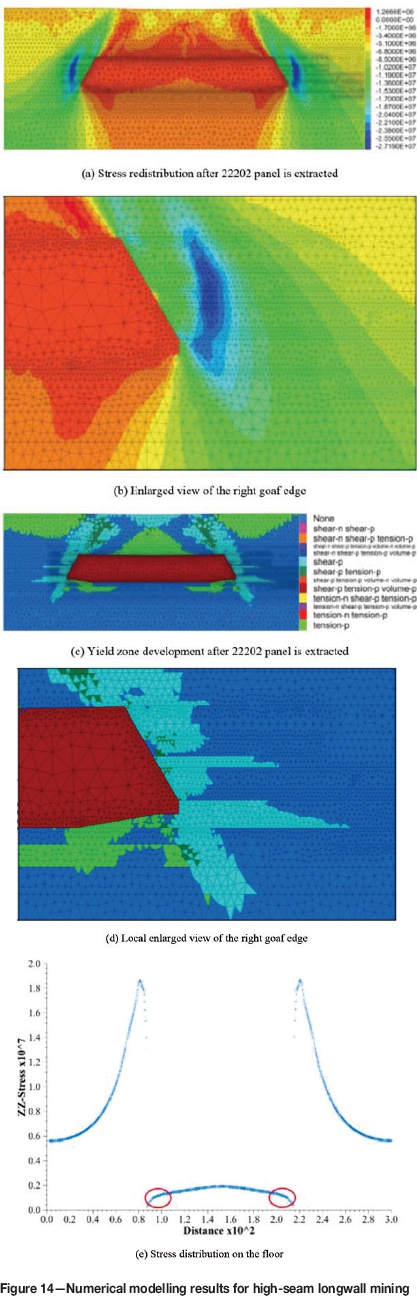
As the mining height is approximately the same with CLTCC, the yielded zone is also approximately the same. However, as there are curved section on either side of the panel, the goaf pressures within these sections are larger (blue areas), which leads to slightly lower abutment pressure than that in CLTCC.
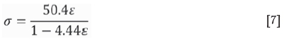
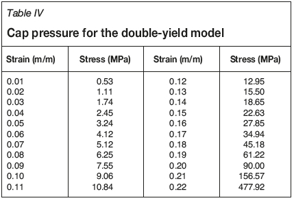
As the goaf configuration in MLM is different, different goaf parameters need to be determined. The process is similar to that for LMSG. As the mining height for the upper single slice in MLM is lower, the height of caved zone must consequently be lower. The caved zone involves two overlying strata directly above the coal seam; that is, 2.2 m fine sandstone and 6.4 m sandy mudstone. Thus, the height of the cave zone above coal seam is 8.6 m. The upper slice is 2.5 m, thus it is calculated that b = 1.3, and maximum strain £m = 0.225 m/m. Still taking ac= 30 MPa, hence E0= 50.4 MPa, the expression for cap pressure (Table IV) is therefore:
A simple model with dimensions 1 m (length) χ 1 m (width) χ 2 m (height) was also built to obtain the reasonable parameters for the goaf and ensure that the strain-stress relationship satisfies Equation [7]. Loading was simulated by applying a velocity on the top surface with the bottom surface and four side surfaces fixed. The input parameters were fitted by an iterative change in the bulk and shear moduli, the angle of dilation, the angle of friction, and the density of the goaf material. By trial and error, the final properties in Table V were obtained The volumetric strain, vertical stress contours, and stress-strain matching curves of the two methods are shown in Figure 15. The numerical modelling results for MLM are shown in Figure 16.


It is demonstrated in Figure 16 that the stress concentration areas (dark blue areas) are smaller than with any other method. Due to the effect of the goaf, the stress concentration areas are located above, and not within, the coal seam as many numerical modelling exercises have concluded in the past. The yielded zone is smaller than with any of the other methods. In addition, the caved zone above the coal seam is 8.6 m, which is smaller than for any other methods, thus leading to a greater degree of compaction. The peak abutment pressure is 20 MPa, which is lower than for any other methods. The results verify the conclusion from the theoretical analysis, that the goaf and surrounding rock mass affect each other: thus, the more load the goaf bears, the lower the abutment pressure, and vice versa. As mining of the lower slice leads to the same mining height as with CLTCC, the modelling process is the same as for CLTCC and therefore is not included here.
Field trial and observations
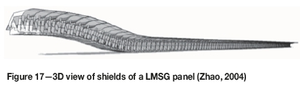
The study so far suggests that the goaf edge is the area where pressure is smallest in the entire longwall panel system, therefore the ground control problems here are minimum. The research results guided the choice of LMSG for practical application for mining of the panels. The 3D views of the shields of 22204 LMSG panel are shown in Figure 17. The unique panel configuration requires unique mining operations (triple sections mining technology) which is different from other methods (Zhao, 2004; Qiao, 2015).
The field observations, including measurements of stress and roadway deformation, were carried out when the face was about 300 m away from set-up room of 22204 panel. For comparison, the same data for the 22202 intake entry and gas-drainage entry was also obtained during the extraction of 22202 panel. Figure 18 shows the support design and the variation in stress and convergence with distance from the face.

Figure 18b shows that roof stress of 22202 gas-drainage entry is slightly lower than that of 22202 intake entry, which indicates the interaction between goaf and surrounding rock mass, i.e., the mining height is lower at the curved section, thus leading to a higher load borne by the goaf, which results in lower roof pressure in the intake entry than the gas-drainage entry on the other side (without a curved section). Furthermore, the roof pressure of 22204 intake entry remains under 1 MPa; this is believed to be due to 22204 intake entry being located under the edge of the goaf of 22202 panel. As aforementioned, the edge of the goaf is the most destressed area in the entire longwall system. Therefore, 22204 intake entry is independent of abutment pressure. The principle is similar to the roadways for lower slices of MLM located directly within the destressed zone, that is, the goaf resulting from the upper slice.
Figure 18 shows that the roof-to-floor convergence for all three roadways increases with increasing distance to the working face, but this is not obvious for 22204 intake entry. Roof-to-floor convergence of 22202 intake entry is the largest, because the location of the entry is the same as in CLTCC and the roof consists of coal. The 22202 gas-drainage entry has a relatively smaller roof-to-floor convergence, because the entry is located along the immediate roof of rock, which is much more competent than a coal roof. In addition, due to the interaction between the goaf and surrounding rock mass, the pressure around the entry is smaller, leading to smaller roof-to-floor convergence. According to the records of the mine, during the extraction of 22202 panel, no roof falls occurred. The roof-to-floor convergence of 22204 intake entry is the smallest, and the deformation of the roof results only from sagging due to gravity. Rib-to-rib convergence of 22202 intake entry is larger than for 22202 gas-drainage entry and that of 22204 intake entry, which is the smallest. Rib-to-rib convergences of 22202 intake entry and 22202 gas-drainage entry increase with distance to the working face, while that of 22204 intake entry does not show any relationship with the distance to the working face, demonstrating that the entry is independent of abutment pressure. This indicates that the stress environment is favourable for entry support and maintenance. The field observations demonstrate that the support design shown in Figure 18a ensured the safe operation of the entry, and mining took place without any accidents.
Applicability of the approach
The approach is best adopted for coal seams with thicknesses greater than 5 m (Wang etal., 2017). LMSG has also been used for coal seams with dip angles of more than 52° (Zhao, Wang, and Su, 2017). As has been shown in this paper, the two adjacent panels must be extracted sequentially, and the entry of the future panel should be developed at least 6 months (preferably one year) after the previous panel has been mined. This point must be kept in mind when a coal mine plans to use the approach. LMSG is preferred for coal seams with a low gas content. With appropriate measures, such as pre-drainage of gas through goaf boreholes or cross-measure drill-holes, grouting, employing an outer offset configuration with a slender pillar in between, or leaving a coal layer between two adjacent panels as shown in Figure 19, LMSG can also be applied for coal seams with a higher gas content. The author has proposed the use of geosynthetic materials (such as membranes) to isolate the entry from the goaf (Editorial Committee, 2015), which is the topic of further research. Furthermore, coal mines currently using LMSG are all single-entry or two-entry systems and are found only in China and Russia. Therefore, additional research should be done to assess the performance of panel systems with three, four, and more entries.

Conclusions
The equilibrium state after the extraction of longwall panels is the result of interaction between the goaf and the surrounding rock mass. Theoretical analysis, physical modelling, numerical modelling, and field observation were carried out for 22202 and 22204 panels in Zhenchengdi coal mine to study the interaction . The main conclusions are as follows.
(1) Different panel layouts lead to different panel configurations and surrounding rock pillar or rock mass configurations. Goaf behaviour has a significant influence on stress distribution and failure of the surrounding coal and rock mass, and should not be ignored in numerical modelling.
(2) Physical modelling of the movement of overlying strata and goaf development shows that caving lines and angles of break develop, and the angle of break has an important influence on goaf, coal, and rock mass configurations as well as stress distribution. The angle of break was used for numerical modelling. Stress monitoring indicates that the abutment pressure on the side with the curved section of the HSLM panel is lower than that in CLTCC, while the pressure distributed within the curved section is higher than that of CTLCC.
(3) A double-yield constitutive model was used to simulate goaf material. The results show that different goaf configurations lead to different stress distributions; the greater the load that the goaf bears, the less the abutment pressure and vice versa. The abutment pressure, stress concentration factor and yield zone would be larger and the elevation of yield zone would be lower without taking the influence of goaf into account. Goaf pressures of curved section employing HSLM and LMSG are larger than those in MLM and CLTCC. When one slice is being extracted in MLM, the goaf pressure is larger than for any other method, and the stress concentration zone and yield zone are smaller. Critical panel widths are not reached for all methods. For all methods, the stress of the goaf edge is the smallest in the entire panel system.
(4) Field monitoring indicates that the front abutment pressure within the entry on the side of the panel with a curved section (gas-drainage entry) is higher than that of the entry on the other side (intake entry). The goaf edge is the most destressed and energy-released zone, and the entry is independent of abutment pressure.
LMSG is helpful for extraction of coal deposits experiencing high ground pressure or related problems, and the technology has potential to be utilized in many countries worldwide. Interested parties may contact the authors regarding the intellectual property and application of the technology in different settings.
Acknowledgement
This work was supported by the National Natural Science Foundation of China (Grant no. 51404270); Fundamental Research Funds for the Central Universities (Grant no. 2011YZ10), and China Scholarship Council (Grant no. 201506430011). The authors extend special thanks to leaders Xinmin Fan, Zhongbao Chang, and their colleagues at Xishan Mining Area for their help and cooperation during the field observation. We are indebted to China National Coal Association, who awarded Grand Prize for the application of LMSG at Zhengchengdi Colliery.
References
Campoli, A.A., Barton, T.M., Dyke, F., and Gauna, M. 1993. Gob and gate road reaction to longwall mining in bump-prone strata. US Bureau of Mines. [ Links ]
Du, J.P. and Meng, X.R. 2009, Mining Technology. China University of Mining and Technology Press, Xuzhou [in Chinese]. [ Links ]
Editorial Committee of National License Examination for Primary Registered Construction Engineers. 2015. Municipal Utilities Engineering Management and Practice. 4th edn. China Architecture & Building Press [in Chinese]. [ Links ]
Esterhuizen, E., Mark, C., and Murphy. M. 2010. Numerical model calibration for simulation coal pillars, gob and overburden response. Proceeding of the 29th International Conference On Ground Control in Mining, Morgantown, WV. West Virginia University. pp. 46-57. [ Links ]
Ghabraie, B., Ren, G., Zhang, X., and Smith, J. 2015. Physical modelling of subsidence from sequential extraction of partially overlapping longwall panels and study of substrata movement characteristics. International Journal of Coal Geology, vol. 40. pp. 71-83. [ Links ]
Itasca Consulting Group Inc. 2012. Fast Lagrangian Analysis of Continua in 3 Dimensions, Version 5.0, User's Guide. Minneapolis, MN. [ Links ]
Morsy, K. and Peng, S.S. 2002. Numerical modeling of the gob loading mechanism in longwall coal mines. Proceedings of the 21st International Conference on Ground Control in Mining, Morgantown, WV. West Virginia University. pp. 58-67. [ Links ]
Pappas, D.M. and Mark, C. 1993. Behavior of simulated longwall gob material. US Bureau of Mines. [ Links ]
Qian, MG., Shi, P.W, and Xu, J.L. 2010. Ground pressure and strata control. China University of Mining and Technology Press, Xuzhou [in Chinese]. [ Links ]
Qiao, J. 2015. Julia sets and complex singularities of free energies. Memoirs of the American Mathematical Society, vol. 234. no. 1102. [ Links ]
Peng, S.S.1978. Coal Mine Ground Control. Wiley-Interscience. [ Links ]
Peng, S.S. 22006. Longwall Mining. 2nd edn. West Virginie University, Morgantown, WV. [ Links ]
Salamon, M. 1990. Mechanism of caving in longwall coal mining. Rock Mechanics Contributions and Challenges: Proceedings of the 31st US Symposium on Rock Mechanics, Golden, CO. Hustrulid, W.A. and Johnson, G.A. (eds.). Balkema, Rotterdam. pp. 161-168. [ Links ]
Wang, J., Wang, Z., and Yang, S.A. 2017. Coupled macro- and meso-mechanical model for heterogeneous coal. International Journal of Rock Mechanics and Mining Sciences, vol. 94. pp. 64-81. [ Links ]
Wang, P.F., Zhao, J.L., Yogingder, P.C., and Wang Z.Q. 2017. A novel longwall layout approach for extraction of deep inclined coal deposits. Minerals, vol. 7, no. 4. p. 60. doi:10.3390/min7040060 [ Links ]
Weishen, Z., Yong, L., Shucai, L., Shugang, W., and Qianbing, Z. 2011. Quasi-three-dimensional physical model tests on a cavern complex under high in-situ stresses. International Journal of Rock Mechanics and Mining Sciences, vol. 48, no. 2. pp. 199-209. [ Links ]
Wilson, A.H. 1981. Stress and stability in coal ribsides and pillars. Proceedings of the First International Conference on Ground Control in Mining. Morgantown, WV. West Virginia University. pp. 1-12. [ Links ]
Yavuz, H. 2004. An estimation method for cover pressure re-establishment distance and pressure distribution in the gob of longwall coal mines. International Journal of Rock Mechanics and Mining Sciences, vol. 41, no. 2. pp. 193-205. [ Links ]
Zhao, C., Hebblewhite, B.K., and Galvin, J.M. 2000. Analytical solutions for mining induced horizontal stress in floors of coal mining panels. Computer Methods in Applied Mechanics and Engineering, vol. 184. pp. 125-142. [ Links ]
Zhao, J.L. 2004. Study on whole seam longwall mining with split-level gateroad. Journal of China Coal Society, vol. 2. pp. 142-145 [in Chinese]. [ Links ]
Zhao, J.L. 2004. Triple sections mining technology (TSMT) in LMSG in thick coal seams. [ Links ] Chinese patent 2004100395750, 10 February 2004 [in Chinese].
Zhao, J.L. 1998. Whole seam longwall mining with split-level gateways (LMSG) in thick coal seams. [ Links ] Chinese patent ZL98100544.6, 18 February 1998 [in Chinese].
Zhao, J.L., Wang, P.F., and Su, Y. 2017. An innovative longwall mining technology in Tangshan coal mine, China. Minerals, vol. 7, no. 1. pp. 14. doi:10.3390/min7010014 ♦ [ Links ]
Paper received Jun. 2017
revised paper received Oct. 2017

