


Servicios Personalizados
Articulo
 Inglés (pdf)
 Articulo en XML
 Referencias del artículo
Indicadores

Links relacionados
-
 Citado por Google
 -
 Similares en Google
Compartir

 Permalink
Journal of the Southern African Institute of Mining and Metallurgy
versión On-line ISSN 2411-9717
versión impresa ISSN 2225-6253
J. S. Afr. Inst. Min. Metall. vol.118 no.6 Johannesburg jun. 2018
http://dx.doi.org/10.17159/2411-9717/2018/v118n6a11
INFACON XV: INTERNATIONAL FERRO-ALLOYS CONGRESS 2018
Basic parameters in the operation and design of submerged arc furnaces, with particular reference to production of high-silicon alloys
T.E. Magnussen
Vatvedt Technology AS, Norway
SYNOPSIS
A review of the basic parameters in the operation of submerged arc furnaces is given. The importance of controlling the electrical operating parameters in accordance with the principles presented by Jens Westly in the 1970s is highlighted.
Basically, the specific energy consumption for production of high-silicon alloys depends on the silicon recovery and the furnace efficiency. Silicon recovery depends mainly on the raw material quality, but also on furnace design. The furnace efficiency depends on the furnace operating resistance and the loss resistance, which are again related to the furnace design.
A case from practical furnace operation is presented, showing how the furnace dimensioning and design affect the furnace efficiency and hence the specific energy consumption. Possibilities for further improvement of furnace efficiency and reduction of the loss resistance are discussed.
Keywords: submerged arc furnaces, high-silicon ferroalloys, electrical operating parameters, specific energy consumption, furnace efficiency factor, loss resistance.
Introduction
It is the author's impression that chemical reactions and equilibria have normally been the main focus in the evaluation and studies of process performance of high-silicon alloys production. Electrical operating parameters did not always receive the same degree of attention from metallurgists.
In the author's experience, it is very important to also pay attention to electrical parameters in furnace operation.
Operating resistance and the Westly factor
For a three-phase furnace, the operating resistance R in ηιΩ is defined as follows:
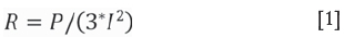
where P is the furnace power in kW, measured on the primary side of the furnace transformers, and I is the electrode current in kA.
The operating resistance is selected by the furnace operator within certain limits, determined by the furnace mix composition, to obtain a satisfactory electrode penetration and good tapping conditions.
The normal way of controlling the operating resistance is to operate the furnace on constant electrode current by adjusting the electrode positions, and at the same time maintaining a constant furnace load.
The operating resistance depends on the required quality of the product, the raw material properties, the composition of the raw material charge mix, and optimum utilization of electrical energy.
For a given process and charge mix composition, it is a matter of experience to find the optimum operating resistance.
In the early days of the ferroalloy industry, the fundamental formula in furnace design was the Andreae formula, introducing the k-factor (Andreae, cited in Westly, 1974):

where R is the operating resistance in mQ, D is the electrode diameter in metres, and k the peripheric resistance (k-factor) in mQ -m.
According to Andreae, the value of the k-factor varies with the process, the raw materials, and the specific load of the electrodes.
Later, adjustments were proposed to the Andreae formula by Kelly (Kelly, cited in Westly, 1974), Persson (Persson, cited in Westly, 1974), and others, suggesting how the value of the k-factor depended on the power density in the electrodes.
Jens Westly studied operating data from a large number of electric reduction furnaces, and published the result of his work on several occasions during the 1970s (Westly, 1974, 1975, 1979). These references are highly recommended.
Westly suggested the following correction of the Andreae formula:
where k is the k-factor in mQ -m, and i the electrode current density in A/cm2.
By combining Equations [2] and [3], Westly (1974) deducted the following correlation:

where I is the electrode current in kA, and P the furnace power in MW.
Based on the above, Westly introduced a new factor, the Westly factor (C3) which is defined as:

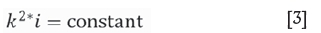
For a given process and a given raw material mix composition, the value of the Westly factor (C3) is basically constant and independent of the furnace load. Reference is made to the furnace load diagram given in Figure 1.
The Westly factor has been found to be extremely useful as a guideline for furnace operation and dimensioning, particularly in relation to upscaling of furnaces.
The principle of heat distribution
Westly also (1974) introduced the principle of heat distribution.
Equation [1] rearranged gives the formula for the furnace load P (kW):

where R is the operating resistance in mQ and I the electrode current in kA.
With reference to the above formula, furnace operators will normally tend to operate on the highest possible operating resistance in order to obtain the highest possible load on their furnace. However, there is a practical limit for the operating resistance that can be used, determined by the heat distribution factor C:

where PC is the energy generation in the furnace charge, Pis the total energy generation, R is the operating resistance, and RC the resistance of the furnace charge.
C may take values between 0 and 1. As Rc is given by the raw material mix composition, C is controlled by the choice of the furnace operating resistance R.
If R is too high compared to RC, the proportion of the total energy input consumed in the melting of raw materials will be too high, and too little will be available for reduction.
This phenomenon is well-known from production of high-silicon alloys. If a furnace is operated on too high an operating resistance compared to the resistance of the charge mix, too much of the energy input will be used for melting of raw materials compared to the energy available for reduction of silicon. This will result in an excess of slag in the furnace and insufficient reduction of silicon, as well as impurities such as aluminium and calcium. This situation may be interpreted as a problem with the carbon balance, whereas the real cause of the problem is that the operating resistance is too high compared to the resistance of the charge mix.
Typical signs are slag formation and low metal temperatures, causing tapping problems. Further, the electrical instruments will tend to show little response to raising or lowering of the electrodes, indicating that the current does not pass from the electrode tips, but from the sides of the electrodes, causing abnormal electrode wear.
To conclude, the operating resistance cannot be chosen at random, but in due consideration of the resistivity of the charge mix.
The significance of the furnace reactance
For a three-phase furnace, the furnace reactance X in mQ is defined as follows:

where Q is the reactive furnace power in kVAr, measured on the primary side of the furnace transformers, excluding the load of capacitor banks, and Iis the electrode current in kA.
Whereas the furnace load is depending on the operating resistance and the electrode current, it is independent of the furnace reactance.
The reactance must be taken into account when designing the transformers for a new furnace. The furnace reactance affects the required transformer capacity as well as the secondary voltage range for the transformers. It also affects the size of the capacitor banks for correction of the power factor on the electrical power supply grid.
Somewhat simplified, we can say that the furnace reactance is proportional to the area surrounded by the current circuit.
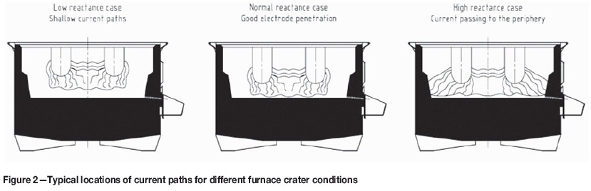
The furnace reactance increases with increasing electrode spacing, and decreases with increasing electrode diameter. A high electrode holder position and low electrode tip to hearth position, with current paths located at a low level in the furnace crucible, will give a high furnace reactance, and vice versa.
Based on experience, it is worthwhile to register and study the value and the trends of the furnace reactance in daily operation, since it gives an indication of factors such as the electrode length and electrode penetration. In other words, it gives interesting information regarding the operating conditions of the furnace.
Figure 2 indicates the typical locations of the current paths for different furnace crater conditions.
Furnace power factor
A consequence of the Westly formula is that the operating resistance R decreases with increasing furnace size.
Referring to the expression for the furnace power factor:

where Z is the furnace impedance in mQ,
a natural consequence of increasing furnace size is that the furnace power factor decreases. The power factor of large furnaces today is normally less than 0.707. At the time, some people thought this may be a problem for the furnace operation; but normally, it is not.
However, with decreasing power factor, it is becoming more difficult to balance the power load and the charge mix consumption between the electrodes in the furnace. If the power factor is very low, towards 0.5 and lower, this balance becomes quite critical, since the electrode to hearth resistance is fairly close to the short circuit condition
Today, most power supply companies require installation of equipment for power factor compensation in order to avoid too low a power factor on the power grid. Capacitor banks are installed for this purpose. The most common, simple and sturdy arrangement is to install capacitor banks in shunt connection on the primary side of the furnace transformers. However, if the furnace power factor is very low, it is normally preferable to install the capacitor banks in series. In this case, the problems of unbalance of the load and charge mix consumption between the electrodes as described above can be avoided.
Electrical parameters for each electrode
The resistance and reactance values calculated as described above give the average values for the electrodes in a three-phase furnace, based on the active and reactive power measured on the primary side of the furnace transformers.
It is also interesting to establish electrical measurements for each electrode in order to monitor and control the conditions on each phase.
These measurements have to be based on a secondary voltage measurement between each phase and the furnace hearth. For this purpose, we measure the voltage between knife contacts on the electrode casing and an artificial zero point underneath the furnace.
Based on the secondary voltage and the secondary current measurement, it is possible to measure active power, reactive power, resistance, and reactance for each electrode.
The challenge with these measurements is the strong electromagnetic field surrounding the furnace, which causes induction in the cables for voltage measurement, thereby influencing the accuracy of the electrical data. Even though we try to reduce the influence of the induction by symmetrical arrangement of the cabling around the furnace and adjustable resistances in the measurement circuits, there will still be some inaccuracy in the voltage measurements and the electrical data deduced from them.
Factors affecting the specific power consumption for high-silicon alloys
It is well known that the specific power consumption (kWh/mt Si) depends on the silicon recovery.
Above all, the silicon recovery is dependent on the raw material quality and the charge mix composition. The use of reductants with high reactivity versus SiO gas will increase the silicon recovery. The use of reductants of smaller size will increase the available surface area of the reductants for exposure to SiO gas, and will therefore be beneficial for increasing the silicon recovery.
Furthermore, the silicon recovery is also affected by the furnace design.
The following features of our furnace design are implemented to improve the silicon recovery:
> Design of day bins and furnace bins to avoid segregation
> Rotating charging tubes
> Rotating furnace body.
In particular, the use of rotating charging tubes has turned out to be very beneficial in order to improve the silicon recovery.
However, the specific power consumption is also dependent on the furnace efficiency factor.
The furnace efficiency factor indicates how efficiently the supplied electrical energy is being utilized in the furnace:

where
η is the furnace efficiency factor P is the furnace power in MW
Pl is the power in MW lost by ohmic resistance in secondary conductors and electrodes, as well as by induction loss and other electrical losses.
The specific power consumption for production of highsilicon alloys can be expressed by the following formula:

where η is the furnace efficiency factor, μ is the silicon recovery (μ = 1 corresponds to 100% silicon recovery), and K1and K2are constants.
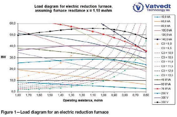
With reference to the data given by Schei, Tuset, and Tveit (1998), the formula for the specific power consumption can be written as follows:

Figure 3 shows the specific power consumption as a function of the silicon recovery for different values of the furnace efficiency factor.
The specific power consumption decreases with increasing furnace efficiency and increasing silicon recovery. In order to reduce the specific power consumption, we need to affect these two factors.
The furnace efficiency factor can also be expressed by the following formula:

where R is the total resistance or operating resistance, as referred to above, and RLis the loss of resistance in secondary conductors, electrodes, and by induction.
The furnace efficiency increases with increasing R and with decreasing RL. Whereas R is basically selected by the
furnace operator as mentioned above, Rl is determined by the furnace design, physical dimensions, and electrical conditions in the furnace crucible.
The furnace operating resistance R depends on the charge mix composition and the raw material quality. The main factors that cause an increase in the operating resistance R are the following:
> Smaller sizing of reductants
> Increased proportion of coal in charge mix
> Use of wood chips.
The above measures should be used and are being used by furnace operators today to increase the furnace efficiency and hence reduce the specific energy consumption. These measures come in addition to the effect of using more reactive reductants in order to improve the silicon recovery as mentioned above.
The furnace loss resistance RLdepends on furnace design and dimensioning. The following factors contribute to decreasing loss resistance:
> Materials with high electrical conductivity in furnace components
> Optimized cross-sectional area of current conductors
> Nonmagnetic materials to reduce eddy currents.
We take all these factors into account as part of our furnace design, with the aim to achieve the lowest possible loss resistance.
In addition, the loss resistance can be influenced by the conditions in the smelting crater, as shown in the example below.
Examples from practical furnace operation
Equation [12] is very useful for analysing furnace performance, as demonstrated by the following example.
The author once had the opportunity to study two silicon metal furnaces in the same plant and of the same capacity, operating at about the same furnace load, using the same raw materials and charge mix composition.
The strange thing about these furnaces was that, in simplified terms, they had about the same silicon recovery, but not the same specific power consumption.
Table I lists the data for the two furnaces, A and B, for a given reference period. Using the above formulae, the furnace efficiency factor η and the loss resistance Rl were calculated. In addition, a measurement of the short circuit resistance and the short circuit reactance was carried out by melting down the furnace and taking the electrical readings with the electrodes resting on the furnace hearth.
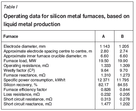
As shown in the table, the furnace efficiency factor is higher and the loss resistance lower for furnace B than for furnace A. In addition, the silicon recovery is somewhat higher.
It is thought that the reason for the higher furnace efficiency and lower loss resistance for furnace B compared to furnace A is the larger electrode diameter and smaller electrode spacing. It seems reasonable that the larger electrode diameter on furnace B is at least part of the reason for the difference in loss resistance.
Moreover, the electrodes had an inclination with the electrode tips pointing towards the periphery of the furnace crucible, probably caused by an inactive zone with a solid cone in the centre of the furnace. This phenomenon was more predominant on furnace A than on furnace B. Given this factor, there is reason to believe that part of the current in the furnace crucible was passing from the outside of the electrodes near the electrode tips, out to the carbon sidewall lining and along the periphery of the furnace crucible over to the neighbouring electrodes. The wear pattern of the electrodes also supported this theory, with higher wear on the electrode surface facing the carbon sidewall lining.
The short circuit measurements also support the above theory. The calculated short circuit resistance was about 13% higher on furnace A than on furnace B, and the calculated short circuit reactance was about 23% higher. Furthermore, this supports the above comments with respect to how the location of current paths in the furnace crater has an influence on the furnace reactance.
As a consequence of the above findings, the electrode spacing on furnace A was reduced, resulting in a substantial improvement in the furnace performance.
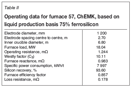
Table II lists the data for the furnace supplied by Vatvedt to ChEMK in Chelyabinsk, Russia in 2014, for the production of ferrosilicon. Compared to the data for the silicon metal furnaces above, the furnace efficiency is higher and the loss resistance is lower.
Consequences of increasing furnace size
As mentioned above, the operating resistance decreases with increasing furnace size. Normally, the loss resistance also decreases with increasing furnace size, due to the increased cross-sectional area of the current conductors. Therefore, generally, increasing the furnace size has no adverse effect on the furnace efficiency.
However, large furnaces are more sensitive to variations in raw material quality. A consistent quality of raw materials and electrode paste is very important in order to achieve stable operating conditions and good efficiency for large furnaces. The consequence of operational disturbances and furnace shutdowns are normally more severe for a large furnace than for smaller ones.
Generally, the investment cost per megawatt and the manpower cost per ton of product is lower for large furnaces. In our opinion, this is the main reason why large furnaces are preferable to smaller furnaces for new projects of a given overall production capacity in an established industrial environment.
Further developments in furnace design
Vatvedt has recently been working on improvements in design of the electrode column, including the development of contact clamps and pressure rings of our own manufacture. Our company supplies contact clamps and pressure ring segments made of pure electrolytic copper. The water-cooled shields are made of stainless steel.
In particular, we are now looking at the design of the area of the electrode column above the top of the contact clamps. Figure 4 illustrates the conventional design of this area.
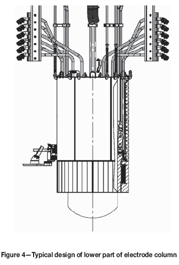
A well-known problem in operation of furnaces of this design using S0derberg electrodes, particularly for large furnaces, is that there is an abundance of thermal energy developed in the area above the contact clamps, caused by induction heating due to the strong electromagnetic fields. This surplus heat causes melting and heating of electrode paste; sometimes resulting in overheating of the liquid paste, paste segregation and high liquid paste levels. This is resulting in poor quality of the baked electrode, causing disturbances in the electrode operation and increased risk of hard as well as soft electrode breakages (Skjeldestad et al., 2015).
When considering this problem in more detail, calculations have confirmed that with the conventional design of this area, the available heat generation by induction heating is much larger than what is required for melting and heating of the electrode paste before baking. In other words, this is a waste of energy, which is adversely affecting the furnace efficiency.
Based on some initial studies, it is thought that by making some design modifications in the area above the top of the contact clamps, it would be possible to achieve a considerable reduction of the induction heating in this area. This reduction of energy loss will have a corresponding effect on reduction of the specific energy consumption per ton of alloy.
In addition, the problem of overheating and segregation of electrode paste with its adverse effects on electrode quality and operation, which is the case on many furnaces today, is likely to be eliminated. Therefore, it will be a win-win situation.
Even with this reduction of the induction heating above the top of the contact clamps, calculations have shown that there will still be enough induction heating available for melting and heating of the electrode paste.
Conclusions
It is very important to pay attention to electrical parameters in furnace operation. The studies conducted and the formulae developed by Westly in the 1970s are very useful as guidelines for furnace operation as well as for furnace dimensioning, particularly in relation to upscaling of furnaces.
The specific power consumption (kWh/mt Si) for the production of high-silicon alloys depends on the silicon recovery as well as on the electrical efficiency of the furnace, expressed as the furnace efficiency factor. The specific power consumption decreases with increasing silicon recovery and increasing furnace efficiency.
Above all, the silicon recovery is dependent on the raw material quality and the charge mix composition. The silicon recovery is also affected by the furnace design.
The furnace efficiency factor depends on the operating resistance of the furnace, which again depends on the resistivity of the furnace charge mix. Smaller sizing of the reductants, an increased proportion of coal, and use of wood chips will contribute to increased resistivity of the charge mix, which will make it possible to operate with an increased operating resistance.
Further, the furnace efficiency factor is depending on furnace design and dimensioning, which is affecting the electrical losses from the furnace. The importance of proper design and material selection for furnace components are highlighted. The significance of the furnace dimensioning is illustrated by an example from practical furnace operation.
Possibilities for improvements in furnace design, and the electrode column design in particular, were highlighted with the aim of reducing electrical losses and hence improving furnace efficiency even further.
References
Schei, A., Tuset, J.K., and Tveit, H. 1998. Production of high silicon alloys. Tapir Forlag, Trondheim, Norway [ Links ]
Skjeldestad, A., Tangstad, M., Lindstad, L., and Larsen, B. 2015. Temperature profiles in S0derberg electrodes. Proceedings of INFACONXIV, the Fourteenth International Ferroalloys Congress, Kiev, Ukraine, 31 May-4 June 2015. pp.327-337. http://www.pyrometallurgy.co.za/InfaconXIV/327-Skjeldestad.pdf [ Links ]
Westly, J. 1974. Resistance and heat distribution in a submerged-arc furnace. Proceedings of INFACON I, the First International Ferroalloys Congress, Johannesburg, South Africa, 22-26 April 1974. pp. 121-127. [ Links ]
Westly, J. 1975. Critical parameters in design and operation of the submerged-arc furnaces. Proceedings of the AIME Electric Furnace Conference, Houston, TX, 9-12 December 1975. pp. 47-53. http://library.aimehq.org/library/books/Electric%20Furnace%201975/Electric%20Furnace%201975%20-%20019.pdf [ Links ]
Westly, J. 1979. Dimensions des fours de reduction pour Fe-Si et d'autres Ferro-alliages, Journal de Four Electrique, Janvier 1979. [ Links ]

