


Services on Demand
Article
 English (pdf)
 Article in xml format
 Article references
Indicators

Related links
-
 Cited by Google
 -
 Similars in Google
Share

 Permalink
Journal of the Southern African Institute of Mining and Metallurgy
On-line version ISSN 2411-9717
Print version ISSN 2225-6253
J. S. Afr. Inst. Min. Metall. vol.118 n.5 Johannesburg May. 2018
http://dx.doi.org/10.17159/2411-9717/2018/v118n5a11
PAPERS OF GENERAL INTEREST
Mathematical simulation and water modelling of liquid steel interaction with an argon bubble curtain in a one-strand continuous casting tundish
A. Cwudziiiski
Department of Metals Extraction and Recirculation, Faculty of Production Engineering and Materials Technology, Czestochowa University of Technology, Poland
SYNOPSIS
The injection of argon into a continuous casting tundish stimulates the zones of active flow (plug and ideal mixing flow) in the liquid steel and reduces the stagnant volume flow. In this research, numerical simulations and laboratory experiments were conducted on the use of a gas-permeable barrier (GPB) in the one-strand tundish. The investigations were aimed at increasing active liquid steel flow in the tundish, without using standard flow-control devices, under variable thermal conditions. The software program ANSYS-Fluent was used to perform numerical simulations. A water model was used to validate the numerical model. The water motion vector fields confirm the hydrodynamic patterns obtained from the computer simulations. The argon flow rate, location of the GPB, and the thermal conditions influence the liquid steel motion in the tundish. The best GPB positions were identified based on the lowest value of stagnant flow at argon injection flow rates of 15 and 5 Nl/min.
Keywords: tundish, argon injection system, steel flow, residence time distribution curves, mathematical modelling, water model.
Introduction
The use of argon in steelmaking protects the liquid steel against the influence of the atmosphere and promotes effective mixing to improve the thermal and chemical homogeneity (Chang, Zhong, and Zou, 2016; Chattopadhyay et al., 2010; Liu and Thomas, 2015; Bai and Thomas, 2001; Smirnov, Efimova, and Kravchenko, 2014; Joo and Guthrie, 1992; Maldonado-Parra et al, 2011; Ganguly and Chakraborty, 2004). The movement of argon bubbles within the liquid steel volume intensifies the mass and momentum exchange processes, thus intensifying the dissolution of technical alloys or scrap, as well as promoting the removal of nonmetallic inclusions during liquid steel refining. Feeding of argon to liquid steel, especially at the tundish stage, should not only provide the expected flow pattern modification, but also ensure the stable operation of the tundish, mould, and secondary cooling zone. The tundish should ensure that the required superheating level in the liquid steel is maintained and protect the steel against oxidation via stable behaviour of the tundish powder (Ilegbusi and Szekely, 1989; Chakraborty and Sahai, 1991; Barreto, Barron Meza, and Morales, 1996; Cloete et al, 2015; Mabentsela, Akdogan, and Bradshaw, 2017). Gas-permeable barriers are used in different tundish types, and it is important to establish their optimal locations in the tundish (Chen et al, 2014; Vargas-Zamora et al, 2004; Smirnov, Efimova, G. and Kravchenko, 2013, 2014; Zhong et al, 2006; Chang, Zhong, and Zou, 2015; Wang et al, 2008; Jiang et al, 2010; Cwudziiiski, 2010a, 2010b, 2010c). The injection of argon stimulates the zones of active flow (plug and ideal mixing flow) and reduces the stagnant volume flow. In the tundish working space, the stagnant volume flow should be as low as possible because the liquid steel resides in these recirculation zones longer than twice the average residence time of steel in the tundish. Therefore, recirculation regions of this type may favour the lowering of temperature, retard the chemical homogenization process in the liquid steel, and hinder impurities, such as nonmetallic inclusions, from floating up to the free surface of the liquid steel. Dispersed plug flow is beneficial in the case of consecutive casting of steel grades with different chemical compositions, because in this flow regime, all fluid elements move in the same direction and at the same velocity, which minimizes the possibility of interpenetration of the streams and mixing of successive steel batches. In contrast, ideal mixing volume flow is advantageous for the chemical and thermal homogenization of liquid steel, which during long casting sequences favourably influences the quality of liquid steel flowing to the mould. For this reason, the overall hydrodynamic pattern should be characterized by the lowest possible contribution of stagnant volume flow and a well-balanced range of dispersed plug flow and ideal mixing volume flow. Argon flow rates in tundishes are much lower than in ladle furnace (LF) treatment, therefore a measurable effect can be achieved in the form of an improved hydrodynamic pattern for reasonable costs related to argon consumption. A further advantage is the reduced quantity of refractory materials (no classical flow-control devices) in the internal working volume of the tundish. This paper presents the results of numerical simulations and laboratory experiments (using a water model) concerning the use of a gas-permeable barrier (GPB) in the one-strand tundish.
Tundish and argon curtain system
Figure 1a shows the one-strand tundish currently used in industry. The nominal capacity of the tundish is 30 t. Currently, the tundish is furnished with a low dam, 0.12 m in height, installed before the bottom step in the stopper-rod system area. The dam incorporates two 0.14 χ 0.05 m overflow windows arranged symmetrically relative to the tundish axis. The inner diameters of the ladle shroud supplying liquid steel to the tundish and tundish nozzle supplying steel to the mould are identical, being equal to 0.07 m. Figure 1b illustrates the locations P1, P2, and P3 of GPB installations in the tundish working volume. In all of the proposed tundish furnishing variants, the flow control device in the form of a low dam was retained. Three argon flow rates, i.e. 5, 10, and 15 Nl/min, were tested. In a 75 mm-high GPB, a 50 χ 750 mm porous plug is positioned in such a manner that, immediately at the sidewalls of the tundish, no argon will flow into the liquid steel. This design was aimed at protecting the tundish brickwork and maintaining the hydrodynamic liquid steel flow condition at the tundish sidewalls, which is characteristic of a tundish not furnished with an argon feed system (Cwudziiiski, 2015). In previous research (Cwudzmski, 2010a, 2010b, 2010c) the optimal position of the GPB in the tundish was found to be in the mid-length of the bottom (position P2, Figure 1b). During the course of the current investigation, two additional gas-permeable barrier locations, shifted by 375 mm from the middle position, were considered, one being shifted towards the stopper-rod system and the other towards the pouring zone (Table I).

Mathematical model
For building the virtual model, the Gambit computer program was used. The numerical domain included tet/hybrid elements of the Tgrid type. The created virtual tundishes with GPB were composed of computational grid, from 161 900 to 165 700 elements. The software program ANSYS-Fluent was used to perform numerical simulations of the behaviour of liquid steel during continuous casting of slabs. The basic mathematical model equations describing the phenomena under consideration examination are as follows (Szekely, 1979; Mazumdar and Evans, 2010):


where g is the gravitational acceleration (m/s2), E the energy (J), keff the effective thermal conductivity (W/mK), p the pressure (Pa), t the time (s), T the temperature (K), u the velocity (m/s), τ the stress tensor (Pa), and ρ the density (kg/m3).
For the description of interactions between liquid steel and argon, the discrete phase model was chosen. The coupled procedure was used to model the influence of argon bubbles on the movement of liquid steel. The thermal energy model included transport energy by conduction and convection under turbulent conditions. For the non-isothermal conditions of steel flow through the tundish, the magnitudes of heat fluxes on particular tundish walls and bottom were determined to be -2600 W/m2, and -1750 W/m2 on the regulator walls. The losses on the steel free surface were -15 000 W/m2. The heat fluxes were determined on the basis of industrial trials, and have been repeatedly used by many researchers and also tested for the considered tundish (Chakraborty and Sahai, 1992; Morales et al, 1999; Miki and Thomas, 1999; Barron-Meza, Barreto-Sandoval, and Morales, 2000; Lopez-Ramirez et al, 2001; Morales et al, 2001; Singh, Paul, and Ray, 2003; Lopez-Ramirez et al, 2004; Zhang, 2005). The wall condition with zero tangential stress was assumed on the free steel table surface. A user-defined scalar (UDS) transport equation was used to calculate the motion of the tracer in the liquid steel. For the description of the turbulence of steel flow through the tundish, the realizable k-ε turbulence model was adopted. In the realizable k-ε turbulence model, constants take on the following values: C1 =1.44, C2=1.9, k=1.0, σε=1.2 (Shih et al, 1995). For the realizable k-ε turbulence approach, turbulent viscosity is not constant, and is calculated on the basis of the actual level of kinetic energy, dissipation rate, and fluid angular velocity (Majumdar, 2011). The physical parameters of the liquid steel are as follows: viscosity 0.007 kg/m s, heat capacity 750 J/kg K, thermal conductivity 41 W/m K, and thermal expansion 0.0001 1/K (Cwudziniski, 2010). The density of liquid steel was described by the polynomial function ρ = 8300 - 0.7105T (Cwudziniski, 2014a). At the tundish inlet, a liquid steel inflow of 1.316 m/s was assumed with turbulence kinetic energy of 0.0173 m2/s2and rate of energy dissipation 0.065137 m2/s3. The kinetic energy and dissipation rate were calculated from the relationships presented by Morales et al. (2000) and Lopez-Ramirez et al. (2001). The initial liquid steel velocity corresponded the continuous casting of 1.5 χ 0.225 m slabs at a speed of 0.9 m/min. The initial liquid steel temperature in the non-isothermal computer simulation was 1823 K.
Physical water model
The 210 litre-capacity tundish model was constructed on a scale of 0.4 (Figure 2). In accordance with the criteria of similarity, the medium simulating the liquid steel was water, which at 20°C has a kinematic viscosity identical to that of liquid steel. The argon gas was simulated by air. It is obvious that air has different physical properties to argon, but it is nearly always use during water modelling of steelmaking processes. The laboratory experiments for the water-air system were performed while meeting the Froude criterion, which ensured the similarity between the gravitational and inertial forces occurring in the physical tundish model and in the actual metallurgical plant was preserved (Krishnapisharody and Irons, 2013).


where L is the characteristic length (m), u the velocity of the continuous medium (m/s), and g the acceleration due to gravity (m/s2).
The basic expression describing the initial volumetric flow rate of water and air in the physical model is as follows:

where Qw/airis the water/air volumetric flow rate (m3/s), Qls/Ar the liquid steel/argon volumetric flow rate (m3/s), and λ the scale factor.
Water flowed into the tundish model at an average flow rate of 30 Nl/min. Air at a flow rate of 0.5, 1, and 1.5 Nl/min was blown into the physical tundish model through a specially designed gas-permeable injection barrier. A camera and a double-cavity laser with a pulse energy of 200 mJ and a wavelength of 532 nm with an optical light knife system with a light beam was used during laboratory trials. For the analysis of the vector flow field, the DaVis 8.0 software program with the 2DPIV module was employed. Seeding in the form of 5 ml glass balls with a density of 1100 kg/m3 (±50 kg/m3) and an average diameter from 9 to 13 um was introduced to the water flowing through the tundish model. The measurement of the vector flow field (PIV) in the physical tundish model was started after four average residence times had elapsed (time of casting one heat). After a steady field of flow was attained in the physical model's working volume, the laser was activated; the beam, passing through the optical system, formed a light plane in which the trajectories of glass ball motion was recorded. The glass balls flowed in accordance with flow directions forming in the water stream. Then a camera equipped with a filter adjusted to the wavelength of light emitted by the laser was activated. The purpose of the filter was to eliminate any ambient interference during recording. For the recording of residence time distribution (RTD) curves, a multimeter with titanium conductometric cells suitable for the measurement of variations in water salinity was used. For the pulse method of adding tracer a 2% salt solution was added to the water. During the stepwise addition of tracer, the batch of water in the tundish model was characterized by a salt concentration about 350 mg/l, whereas the concentration of salt in the water flowing from the ladle model to the tundish model was about 200 mg/l.
Residence time distribution curves and buoyancy number
The hydrodynamic condition in the tundish is described by the RTD characteristics of types (E) and (F), which illustrate the motion of fluid elements between entering and exiting a specific system (Westerterp, van Swaaij, and Beenackers, 1984; Nauman and Buffham, 1983; Wen and Fan, 1975). The relationship between the residence time and the concentration of the substance results from the fact that the fluid elements have a varying time of residence in the system under consideration. A RTD curve can be drawn by adding a tracer in the form of a chemical substance to the fluid flowing into the facility and recording it at the outflow. The tracer can be introduced to the liquid in two ways: either by continuous feeding (step method) in a specific quantity, which enables F-type characteristics to be plotted; or by batchwise feeding of the tracer, so-called pulse tracer feeding, during which an E-type curve is recorded (Rosner, 1986; Levenspiel, 1999; Szekely and Ilegbusi, 1989; Himmelblau and Bischoff, 1968). The flow can be assessed by analysis of the graphic decomposition of the curve. For the quantitative analysis based on the volumes of individual flow types in the type of facilities under consideration in this work, the formulae provided by Sahai and Emi (1996), Mazumdar and Guthrie (1999), and Thomas (2003) can be used. In reality, industrial tundish designs are determined by the sizes of the stagnant volume, dispersed plug and ideal mixing volume flows, and the transient zone. Their quantitative assessment enables the selection of optimal design solutions for a given industrial tundish. Based on the results of Cwudziiiski's (2008) investigations carried out in industrial conditions, a transition zone in the range from 0.2 to 0.8 of (dimensionless) concentration of chemical element was chosen as representative for the tundish under consideration. In order to explain the phenomena occurring in the tundish working volume in relation to the influence of thermal stratification on steel flow, the buoyancy number (Bu), as described by Equation [6], was calculated.

where g is the gravitational acceleration (m/s2), L the depth of liquid steel (m), ∆T the temperature difference between the liquid steel flowing to the tundish and the liquid steel flowing to the mould (K), uavg the average velocity of the steel flow (m/s), and β the thermal expansion (1/K).
The buoyancy number describes the effect of natural convection on the fluid flow pattern, and expresses the ratio of buoyancy forces to inertial forces in the system. A Bu value above 5 indicates that the liquid steel flowing through the tundish will be affected by natural convection, whereas a value < 1 will indicate the influence of forced convection on the motion of the steel.
Results and discussion
Isothermal conditions - flow structure
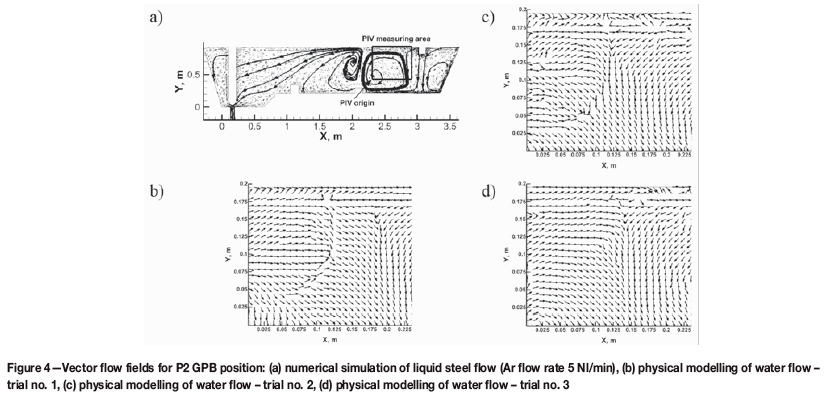
Numerical simulations and laboratory experiments were carried out for all considered variants of GPB position and argon flow rate. It was found that, in overall terms, the hydrodynamic system in the central part of the tundish did not change significantly with increasing argon flow rate, while the modification of the liquid steel movement was determined chiefly by the position of the injection barrier. The results of computer simulations and laboratory experiments are presented in Figures 3-5 for the considered GPB positioning locations and an argon flow rate of 5 Nl/min. In the central part of the tundish with the GPB in position P1, a clear influence of the argon phase on the liquid steel motion is apparent, whereby the liquid steel stream ascends towards the free surface (Figure 3a). On the stopper-rod system side, part of the liquid steel streams descending towards the tundish bottom turn back at the low dam to flow up to the argon injection region. The remaining descending streams in this part of the tundish flow towards the tundish nozzle. On the pouring zone side, a region of interaction of the streams flowing from the argon curtain and the pouring zone is apparent. Both flow regimes meet in the mid-measurement region, whereas the streams flowing from the argon curtain grow in strength as they approach the tundish bottom, penetrating through the tundish feeding streams. Shifting the GPB to position P2 did not significantly influence the overall hydrodynamic pattern in the central part of the tundish (Figure 4a). In this case also, the streams flowing from the GPB and from the pouring zone interact with each other; however, the region of interaction is shifted more towards the pouring zone. Shifting the GPB to position P3 reduces the liquid steel circulation region between the injection barrier and the liquid steel stream flowing into the tundish (Figure 5a). In that case an intensive region of circulation oriented to the free surface, descending according to the feed stream motion, flowing along the bottom towards the GPB, and then being entrained by argon bubbles, forms. In the zone between the GPB and the stopper-rod system, the hydrodynamic pattern in the central part of the tundish features streams descending from the free surface towards the bottom and the nozzle of the tundish. The water motion vector fields for GPB positions no. 1 and 2 confirm the occurrence in the measurement region of the lines of interaction of water streams flowing in from two directions, i.e. from the GPB and from the tundish model feed zone (Figures 3b, 3c, and 3d, 4b, 4c, and 4d). It is evident that the position of the zone of interaction of the abovementioned hydrodynamic patterns gradually moves with time. Disturbances in the vector field are also visible in some places, indicating a dynamism of water movement. Also, the water motion vector fields in the measurement region for the tundish with the GPB in position P3 confirm the hydrodynamic patterns obtained from the computer simulations (Figures 5b, 5c, and 5d). In either case, both the liquid steel and the water flow from the free surface towards the tundish bottom and the stopper-rod system.
Isothermal conditions - residence time distribution curves
Figure 6a shows E-type RTD curves for all tundish furnishing variants under consideration and the argon flow rates tested. In the tundish with the GPB in position no. 1, at an argon flow rate of 15 Nl/min a distinct shift in the curve peak from the Y axis occurs, which indicates an increase in the dispersed plug flow contribution to the overall flow pattern developing in the working space of the facility. When the GPB was moved to position no. 2, on the other hand, the largest increase in the contribution of dispersed plug flow volume was obtained at an argon flow rate of 5 Nl/min. In that tundish variant, a lowering of the peak position relative to the X axis was also obtained, which indicates intensification of the process of tracer spreading within the liquid steel volume, that is, the diversification of the flow pattern. With subsequent shifting of the GPB towards the pouring zone, the argon flow rate significantly influences the dispersed plug flow contribution, because the peaks for the tundish variants under consideration are positioned fairly close to one another relative to the Y axis. In contrast, their positions relative to the X axis differ, which is, obviously, closely related to the mixing power generated by the gas columns, which is the greater the higher the argon flow rate. For the GPB under discussion, laboratory casting sequences (water model) were performed. The F-RTD curves, in the form of points, were juxtaposed with the computer simulation results (Figure 6b). A fairly satisfactory agreement between the water-air experiments and the liquid steel-argon numerical simulations was achieved. Figure 7 presents the percentage contributions of the stagnant volume, dispersed plug, and ideal mixing volume flows. In the case of the GPB, for two locations of its installation and argon flows of 5 and 15 Nl/min, a reduction of the extent of stagnant volume flow was obtained. In the low-dam tundish currently in use commercially, stagnant volume flow accounts for 28%, and dispersed plug flow only 14% (Cwudziniski, 2014b). An increase in the immersed dispersed plug flow was also obtained by increasing the ratio of dispersed plug flow to well-mixed volume flow from 0.24 for the tundish without a GPB to 0.38 and 0.47 for the tundish with the GPB. In the remaining GPB positioning variants and at the proposed argon flow rates, the stagnant volume flow contribution increased to as high as 40% in the tundish with the GPB in position no. 3. Shifting the GPB by another 375 mm towards the pouring zone caused not only an increase in stagnant volume flow, but also definitely decreased the dispersed plug flow contribution to the overall flow pattern to below 5%. Figure 8a shows F-type RTD curves for all tundish furnishing variants under consideration and argon flow rates tested. In the case of the GPB tundish, a definite effect of argon flow rate can be seen with different GPB positions. The laboratory experiments performed, by locating the obtained points in relation to the numerical curve, confirmed the correctness of numerical results for transitions zone behaviour during isothermal conditions (Figure 8b). The range of the transient zone is closely correlated with the dispersed plug flow portion of the overall pattern forming in the tundish working space. Therefore, reduction of the stagnant volume flow portion does not in itself assure hydrodynamic conditions favouring reduction of the extent of the transient zone. When a GPB was used, the most favourable reduction in transient zone range was obtained for the tundish with the GPB in position no. 2 at an argon flow rate of 5 Nl/min (Figure 9). In this case, the reduction of the transient zone decreased the weight of the transient steel slab by 1.5 t, compared to the tundish currently in use commercially. However, the investigation showed that the hydrodynamic conditions created by interaction of the argon phase with liquid steel under isothermal conditions could considerably increase the extent of the transient zone, by as much as 6.8 Mg compared to the commercial tundish.


Non-isothermal conditions - flow structure
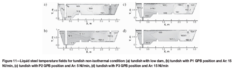
Figures 10 and 11 represent the results of computer simulations of liquid steel flow and temperature for non-isothermal conditions for the three most favourable GPB tundish variants, as selected based on the results obtained for isothermal conditions. The best tundish variants were characterized by the lowest value of stagnant flow for the considered GPB positions and argon flow rate. The hydrodynamic conditions in the low dam tundish (Figure 10a) are described in detail by Cwudziiiski (2014b, 2017). In the tundish with GPB in position P1 with an argon flow of 15 Nl/min, the GPB causes liquid steel to recirculate between the feed zone and the argon injection zone (Figure 10b). The recirculation region is also fed by the backward-flowing streams that flow into the GPB region and, by interacting with argon bubbles, are carried towards the free surface and partially transferred to the recirculation zone. In the zone between the GPB and the stopper-rod system, parts of the streams flow in a horizontal configuration at the free surface. In the stopper-rod system zone at the bottom, part of the streams ascends towards the free surface and the other part flows in parallel along the bottom. With the GPB in position P2 and at an argon flow rate of 5 Nl/min, the liquid steel recirculation zone in the pouring zone is retained (Figure 10c). In contrast, upstream of the low dam, the liquid steel streams clearly descend towards the bottom. The flow of liquid steel in the stopper-rod system zone of the tundish with the GPB in position P2 is similar to that with the GPB in position P1, with the stream descending above the low dam counteracting the formation of the backward-flowing stream. This is particularly evident when the GPB is shifted to position P3, because the feed streams fall towards the low dam and then flow horizontally towards the stopper-rod (Figure 10d). Knowledge of the distribution of liquid steel temperature in the tundish with argon injection system is essential, because argon at ambient temperature is introduced to a high-temperature system. Figure 11 shows maps of the liquid steel temperature fields. The use of the GPB did not cause any drop in the liquid steel temperature due to the plume of argon bubbles flowing through the liquid steel. In the stopper-rod system, also, the liquid steel temperature is 1819 K, which compared to the initial liquid steel temperature value of 1823 K, represents a decrease of only 4 K.
Non-isothermal conditions - residence time distribution curves
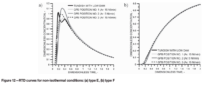
The quantitative analysis of the tundish operation in selected GPB positioning variants for non-isothermal conditions was based on the E- and F-type RTD curves. The RTD curves enabled the assessment of the influence of thermal gradients forming in the bulk of the liquid steel on the hydrodynamic patterns developing in the working space of the facility. Figure 12 shows F- and E-type RTD curves for four tundish furnishing variants. In all of the proposed variants qualified for non-isothermal simulations, an increase in dispersed plug flow was obtained (Figure 12a). The position of the peaks of the E-type RTD curves relative to the X and Y axes is similar, which indicates similar conditions of tracer dispersal in the bulk of the liquid steel. The dimensionless concentration value oscillates around unity, which indicates a considerable degree of dissipation of the feed streams flowing to the tundish. This is also confirmed by an approximately 50% ideal mixing volume flow portion of the overall steel movement pattern. The smallest stagnant volume flow portion of 30.4% was obtained for the tundish with the GPB installed closer to the stopper-rod system and at an argon flow rate of 15 Nl/min (Table II). The distribution of all F-type RTD curves is very similar (Figure 12b). The least advantageous RTD curve shape was obtained with the argon curtain in position no. 3 and an argon flow rate of 15 Nl/min. Compared to the low dam tundish variant, this indicates an increase in the extent of the transient zone and a 0.5 Mg increase in the quantity of steel of the intermediate chemical composition larger by. The remaining GPB positioning variants and the employed argon flow rates of 5 and 15 Nl/min contributed to a reduction in the transient zone extent by 0.6 Mg (Table III). An advantageous reduction in the quantity of the steel of intermediate chemical composition was obtained for two GPB locations, by stimulating the active steel flow and minimizing the stagnant volume flow. Table IV gives the Bu number calculated for the analysed tundish furnishing variants and for non-isothermal conditions. The introduction of argon to the working volume of the tundish caused an increase in average liquid steel flow velocity up to 0.051 m/s with the GPB in position P1. The increase in liquid steel velocity enhances the momentum in the system and increases the influence of inertial forces on the hydrodynamic structure. The minimum influence of natural convection on the hydrodynamic system is confirmed by the low Bu values of below 2. Slightly higher Bu values of 2.68 were obtained for the stopper-rod system zone, which is characterized by a greater height of the liquid steel column. It is chiefly in the region of the stopper-rod system that the largest difference in flow pattern was evident between computer simulations performed for non-isothermal and isothermal conditions.

Summary
► The GPB introduces additional momentum to the system by the interaction between the argon bubbles and the liquid steel, leading to an increase in flow velocity, thus highlighting the role of inertial forces in the modification of the hydrodynamic pattern
► Under non-isothermal conditions, the temperature stratification in the liquid steel will modify the steel flow in regions of the tundish working space remote from the argon injection and tundish feed zones, resulting in a change in the hydrodynamic pattern
► Shifting the GPB towards the feed zone does not favourably influence the extent of the transient zone. This is due to the intensification of the steel mixing process initiated by the feeding stream and the argon plume
► Advantageous hydrodynamic conditions in relation to the transient zone range were obtained for the tundish variant with the GPB positioned closer to the stopperrod system in the mid-length of the bottom of the tundish feed zone
► The modification of the hydrodynamic pattern of liquid steel movement in the GPB tundish depends on the argon flow rate, which is closely correlated with the location of the GPB and the thermal condition of the steel grade being cast.
Acknowledgements
This research work was sponsored by the Ministry of Science and Higher Education under the IuventusPlus programme, project no. IP2014 006973, in the years 2015-2016.
References
Bai, H. and Thomas, B.G. 2001. Turbulent flow of liquid steel and argon bubbles in slide-gate tundish nozzles: Part II. Effect of operation conditions and nozzle design. Metallurgical and Materials Transaction B, vol. 32. pp. 269-284. [ Links ]
Barreto, J. de J., Barron Meza, M.A., and Morales, R.D. 1996. Physical and mathematical modeling of steel flow and heat transfer in tundish under non-isothermal and non-adiabatic conditions. ISIJ International, vol. 36, no. 5. pp. 543-552. [ Links ]
Barron-Meza, M.A., Barreto-Sandoval, J. de J., and Morales, R.D. 2000. Physical and mathematical models of steel flow and heat transfer in a tundish heated by plasma. Metallurgical and Materials Transaction B, vol. 31. pp. 63-74. [ Links ]
Chang, S., Cao, X., Zou, Z. Isac, M., and Guthrie, R.I.L. 2016. Microbubble swarms in a full-scale water model tundish. Metallurgical and Materials Transaction B, vol. 47. pp. 2732-2743. [ Links ]
Chakraborty, S. and Sahai, Y. 1991. Effect of varying ladle stream temperature on the melt flow and heat transfer in continuous casting tundishes. ISIJ International, vol. 31, no. 9. pp. 960-967. [ Links ]
Chakraborty, S. and Sahai, Y. 1992. Effect of holding time and surface cover in ladles on liquid steel flow in continuous casting tundishes. Metallurgical and Materials Transaction B, vol. 23. pp. 153-167. [ Links ]
Chang, S., Zhong, L., and Zou, Z. 2015. Simulation of flow and heat fields in a seven-strand tundish with gas curtain for molten steel continuous-casting. ISIJ International, vol. 55, no. 4. pp. 837-844. [ Links ]
Chattopadhyay, K., Hasan, M., Isac, M., and Guthrie, R.I.L. 2010. Physical and mathematical modeling of inert gas-shrouded ladle nozzles and their role on slag behavior and fluid flow patterns in a delta-shaped, four-strand tundish. Metallurgical and Materials Transaction B, vol. 41. pp. 225-233. [ Links ]
Chen, D., Xie, X., Long, M., Zhang, M., Zhang, L., and Liao, Q. 2014. Hydraulic and mathematics simulation on the weir and gas curtain in tundish of ultrathick slab continuous casting. Metallurgical and Materials Transaction B, vol. 45. pp. 392-398. [ Links ]
Cloete, J.H., Akdogan, G., Bradshaw, S.M., and Chibwe, D.K. 2015. Physical and numerical modelling of a four-strand steelmaking tundish using flow analysis of different configurations. Journal of the Southern African Institute of Mining and Metallurgy, vol. 115. pp. 355-362. [ Links ]
Cwudzinski, A. 2008. Regulation of steel flow in the slab tundish. PhD thesis, Czestochowa University of Technology (in Polish). [ Links ]
Cwudzinski, A. 2010a. Numerical simulation of liquid steel flow in wedge-type one strand slab tundish with a subflux turbulence controller and an argon injection system. Steel Research International, vol. 81, no. 2. pp. 123-131. [ Links ]
Cwudzinski, A. 2010b. Numerical simulation of steel flow through a one strand slab tundish with steel flow control devices. Canadian Metallurgical Quarterly, vol. 49, no. 1. pp. 63-72. [ Links ]
Cwudzinski, A. 2010c. Numerical simulation of liquid steel flow and behaviour of non-metallic inclusions in one-strand slab tundish with subflux turbulence controller and gas permeable barrier. Ironmaking and Steelmaking, vol. 37, no. 3. pp. 169-180. [ Links ]
Cwudzinski,, A. 2014a. Numerical and physical prediction of hydrodynamic conditions in one strand slab tundish. Metallurgical Research & Technology, vol. 111, no. 1. pp. 45-55. [ Links ]
Cwudzinski, A. 2014b. Numerical and physical modeling of liquid steel active flow in tundish with subflux turbulence controller and dam. Steel Research International, vol. 85, no. 5. pp. 902-917. [ Links ]
Cwudzinski, A. 2015. Numerical, physical, and industrial studies of liquid steel chemical homogenization in one strand tundish with subflux turbulence controller. Steel Research International, vol. 86, no. 9. pp. 972-983. [ Links ]
Cwudzinski, A. 2017. Physical and mathematical simulation of liquid steel mixing zone in one strand continuous casting tundish. International Journal of Cast Metals Research, vol. 30, no. 1. pp. 50-60. [ Links ]
Ganguly, S. and Chakraborty, S. 2004. Numerical investigation on role of bottom gas stirring in controlling thermal stratification in steel ladles. ISIJ International, vol. 44, no. 3. pp. 537-546. [ Links ]
Himmelblau, D.M. and Bischoff, K.B. 1968. Process Analysis and Simulation. Wiley, New York. [ Links ]
Ilegbusi, O.J. and Szekely J. 1989. Effect of magnetic field on flow, temperature and inclusion removal in shallow tundishes. ISIJ International, vol. 29, no. 12. pp. 1031-1039. [ Links ]
Jiang, J., Li, J.S., Wu, H.J., Yang, S.F., Li, T., and Tang, H.Y. 2010. Water modeling of molten steel flow in a multi-strand tundish with gas blowing. International Journal of Minerals, Metallurgy and Materials, vol. 17, no. 2. pp. 143-148. [ Links ]
Joo, S. and Guthrie, R.I.L. 1992. Modeling flows and mixing in steelmaking ladles designed for single- and dual-plug bubbling operations. Metallurgical and Materials Transaction B, vol. 23. pp. 765-778. [ Links ]
Krishnapisharody, K. and Irons, G.A. 2013. A critical review of the modified Froude number in ladle metallurgy. Metallurgical and Materials Transaction B, vol. 44. pp. 1486-1498. [ Links ]
Levenspiel, O. 1999. Chemical Reaction Engineering. Wiley, New York. [ Links ]
Liu, R. and Thomas, B.G. 2015. Model of gas flow through porous refractory applied to an upper tundish nozzle. Metallurgical and Materials Transaction B, vol. 46. pp. 388-405. [ Links ]
Lopez-Ramirez, S., Barreto, J. de J., Palafox-Ramos, J., Morales, R.D., and Zacharias, D. 2001. Modeling study of the influence of turbulence inhibitors on the molten steel flow, tracer dispersion, and inclusion trajectories in tundish. Metallurgical and Materials Transaction B, vol. 32. pp. 615-627. [ Links ]
Lopez-Ramirez, S., Barreto, J. de J., Vite-Martinez, P., Romero Serrano J.A., and Duran-Valencia C. 2004. Physical and mathematical determination of the influence of input temperature changes on the molten steel flow characteristics in slab tundishes. Metallurgical and Materials Transaction B, vol. 35. pp. 957-966. [ Links ]
Mabentsela, A., Akdogan, G., and Bradshaw S. 2017. Numerical and physical modeling of tundish slag entrainment in the steelmaking process. Journal of the Southern African Institute of Mining and Metallurgy, vol. 117. pp. 469-483. [ Links ]
Majumdar, P. 2011. Computational fluid dynamics analysis of turbulent flow. Computational Fluid Dynamics Technologies and Applications. Minin I.V. and Minin O.V. (eds.). Intech. Chapter 9, pp. 255-292. [ Links ]
Maldonado-Parra, F.D., Ramirez-Argaez, M.A., Conejo, A.N., and González, C. 2011. Effect of both radial position and number of porous plugs on chemical and thermal mixing in an industrial ladle involving two phase flow. ISIJ International, vol. 51, no. 7. pp. 1110-1118. [ Links ]
Mazumdar, D. and Guthrie, R.I.L. 1999. The physical and mathematical modelling of continuous casting tundish systems. ISIJ International, vol. 39, no. 6. pp. 524-547. [ Links ]
Mazumdar, D. and Evans, J.W. 2010. Modeling of Steelmaking Processes. CRC Press, Boca Raton, FL. [ Links ]
Miki, Y. and Thomas, B.G. 1999. Modeling of inclusion removal in a tundish. Metallurgical and Materials Transaction B, vol. 30. pp. 639-654. [ Links ]
Morales, R.D., Lopez-Ramirez, S., Palafox-Ramos, J., and Zacharias D. 1999. Numerical and modeling analysis of fluid flow and heat transfer of liquid steel in a tundish with different flow control devices. ISIJ International, vol. 39, no. 5. pp. 455-462. [ Links ]
Morales, R.D., Barreto, J. de J., Lopez-Ramirez, S., Palafox-Ramos J., and Zacharias D. 2000. Melt flow control in a multi-strand tundish using a turbulence inhibitor. Metallurgical and Materials Transaction B, vol. 31. pp. 1505-1515. [ Links ]
Morales, R.D., Lopez-Ramirez, S., Palafox-Ramos, J., and Zacharias, D. 2001. Mathematical simulation of effects of flow control devices and buoyancy forces on molten steel flow and evolution of output temperatures in tundish. Ironmaking and Steelmaking, vol. 28, no. 1. pp. 33-43. [ Links ]
Nauman, E.B. and Buffham, B.A. 1983. Mixing in Continuous Flow Systems, Wiley, New York. [ Links ]
Rosner, D.E. 1986. Transport Processes in Chemically Reacting Flow Systems. Butterworth, Stoneham, MA. [ Links ]
Sahai, Y. and Emi, T. 1996. Melt flow characterization in continuous casting tundishes. ISIJ International, vol. 36, no. 6. pp. 667-672. [ Links ]
Singh, R.K., Paul, A., and Ray, K. 2003. Modelling of flow behaviour in continuous casting tundish. Scandinavian Journal of Metallurgy, vol. 32. pp. 137-146. [ Links ]
Shih, T.-H., Liou, W.W., Shabbir, A., Yang, Z., and Zhu, J. 1995. A new k- eddy viscosity model for high Reynolds number turbulent flows. Computers & Fluids, vol. 24, no. 3. pp. 227-238. [ Links ]
Smirnov, A.N., Efimova, V.G., Kravchenko, A.V., and Pismarev, K.E. 2014. Flotation of nonmetallic inclusions during argon injection into the tundish of a continuous casting machine. Part 3. Steel in Translation, vol. 44, no. 3. pp. 180-185. [ Links ]
Smirnov, A.N., Efimova, V.G., and Kravchenko, A.V. 2013. Flotation of nonmetallic inclusions during argon injection into the tundish of a continuous casting machine. Part 1. Steel in Translation, vol. 43, no. 11. pp. 673-677. [ Links ]
Smirnov, A.N., Efimova, V.G., and Kravchenko, A.V. 2014. Flotation of nonmetallic inclusions during argon injection into the tundish of a continuous casting machine. Part 2. Steel in Translation, vol. 44, no. 1. pp. 11-16. [ Links ]
Szekely, J. 1979. Fluid Flow Phenomena in Metals Processing. Academic Press, New York. [ Links ]
Szekely, J. and Ilegbusi, O.J. 1989. The Physical and Mathematical Modelling of Tundish operations, Springer-Verlag, Berlin. [ Links ]
Thomas, B.G. 2003. Modeling study of intermixing in tundish and strand during a continuous casting grade transition. Continuous Casting Tundish Operations. Schade, J. (ed.), vol. 10. pp. 115-127. [ Links ]
Vargas-Zamora, A., Morales, R.D., DIaz-Cruz, M., Palafox-Ramos, J., and Barreto-Sandoval, J. de J. 2004. Inertial and buoyancy driven water flows under gas bubbling and thermal stratification conditions in a tundish model. Metallurgical and Materials Transaction B, vol. 35. pp. 247-257. [ Links ]
Wang, J., Zhu, M.Y., Zhou, H.B., and Wang, Y. 2008. Fluid flow and interfacial phenomenon of slag and metal in continuous casting tundish with argon blowing. Steel Research International, vol. 15, no. 4. pp. 26-31. [ Links ]
Wen, CY. and Fan, L.T. 1975. Models for Flow Systems and Chemical Reactors. Marcel Dekker, New York. [ Links ]
Westerterp, K.R., van Swaaij, W.P.M., and Beenackers, A.A. 1984. Chemical Reactor Design and Operation. Wiley, New York. [ Links ]
Zhang, L. 2005. Fluid flow, heat transfer and inclusion motion in a four-strand billet continuous casting tundish. Steel Research International, vol. 76, no. 11. pp. 784-796. [ Links ]
Zhong, L., Li, L., Wang, B., Jiang, M., Zhu, L., and Chen, R. 2006. Water modeling experiments of argon bubbling curtain in a slab continuous casting tundish. Steel Research International, vol. 77, no. 2. pp. 103-106. [ Links ]
Paper received Feb. 2017
Revised paper received Nov. 2017

