


Services on Demand
Article
 English (pdf)
 Article in xml format
 Article references
Indicators

Related links
-
 Cited by Google
 -
 Similars in Google
Share

 Permalink
Journal of the Southern African Institute of Mining and Metallurgy
On-line version ISSN 2411-9717
Print version ISSN 2225-6253
J. S. Afr. Inst. Min. Metall. vol.118 n.5 Johannesburg May. 2018
http://dx.doi.org/10.17159/2411-9717/2018/v118n5a7
PAPERS OF GENERAL INTEREST
Effect of mould geometry, coating, and plate thickness on the thermal profile of continuous casting moulds
A. Gupta; R.K. Singh; A. Paul; S. Kumar
Research and Development Center for Iron and Steel, Steel Authority of India Limited
SYNOPSIS
A three-dimensional model for heat transfer analysis of continuous casting mould plate has been developed to predict the hot face temperature. Actual geometry has been considered by incorporating the bolt holes used for fixing bolts to tighten the plate with the backup water box, and the effect of these bolt holes on the hot face temperature of the mould plate is analysed. The high thermal conductivity of copper makes it suitable for use as mould plate material where high heat transfer rates are required. However, copper has poor resistance to abrasion and this disadvantage becomes apparent in the lower part of the mould, where severe wear of the copper surface takes place. To eliminate this problem, high-hardness materials like nickel are coated over the copper surface. This does not affect the heat transfer significantly. The purpose of this study is to investigate the effect of the bolt holes, as well as the nickel coating, on the hot face temperature.
Keywords: continuous casting, heat transfer, mould coating.
Introduction
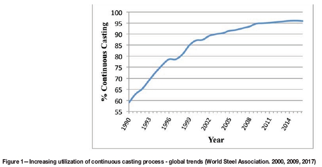
Remarkable advances have been made in the continuous casting of steel, as demonstrated by the increasing use of continuous casting around the globe (Figure 1). Various developments have improved the efficiency of operation and product quality (Janik et al., 2004; Janik and Dyja, 2004; Liu and Zhu, 2006; Thomas et al., 1997; Thomas, 2001; Park et al., 2000, 2002; Samarasekera and Brimacombe, 1979, 1982; Chow et al., 2002; Meng and Thomas, 2003; Santillana et al., 2008).
The mould, which is regarded as the heart of the continuous casting machine, plays a prominent role in the efficiency of the process and strand quality. Owing to the importance of the mould, various significant studies (Janik et al., 2004; Janik and Dyla, 2004; Liu and Zhu, 2006) and model development have been carried out on the thermo-mechanical characteristics of the mould. The central objective of all these studies has been to obtain better heat transfer, dimensional accuracy of cast strands, better surface quality of strands, and longer mould life, etc.
Thomas et al., (1997), Thomas (2001), and Park et al., (2000) used a finite element model for prediction of temperature, distortion, and residual stresses on the mould plate. Park et al., (2000), Samarasekara and Brimacombe (1979, 1982), and Chow et al., (2002), on the other hand, developed mathematical models for predicting the shape of moulds and the temperature field as a function of operating design variables. Similar investigations (Meng and Thomas, 2003; Park et al., 2002; Santillana et al., 2008) are also available in the literature, and all of these point towards strict control of the mould hot face temperature to avoid distortion and thus produce better quality products. Also, generation of thermal stresses on the mould hot face must be avoided to minimize the distortion and resulting wear.
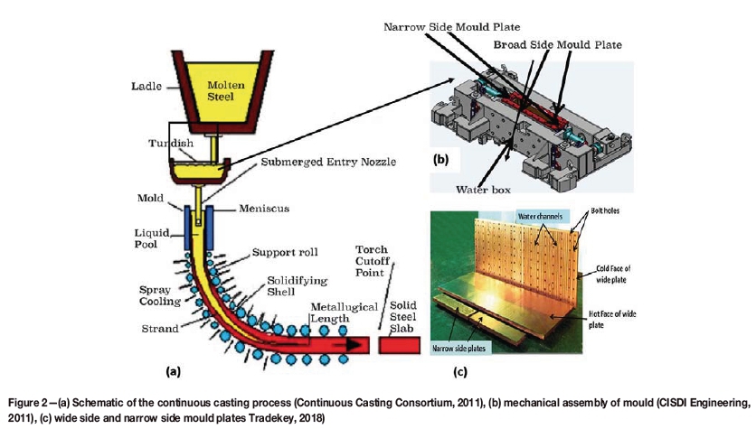
Figure 2a is a schematic of the continuous casting process. Molten steel from the ladle is poured into the tundish and from there into the moulds. In the mould, heat is extracted and the molten steel starts solidifying. As it cools, the steel strand is subsequently pulled downwards by the support rolls and finally cut into slabs. The dimensions of the slab are governed by the dimensions of the mould, which consists of a set of four plates (two narrow side-plates and two broad side-plates) as shown in Figure 2b. The side of the plate in contact with liquid steel or solidifying strand is known as the hot face and the side in contact with the water box is known as the cold face (Figure 2c). On the cold face of the plate an array of water cooling channels is provided to circulate cooling water at high flow rates to extract heat from the plate. Thus heat flows from the molten steel to the cooling water across the mould plate thickness.
Mould heat transfer is the most important parameter in continuous casting in terms of efficiency and quality. The heat removal rate from the mould has to be strictly controlled.
Too high a rate of heat removal may lead to formation or a thicker shell near the mould exit. This causes rapid wear of the mould surface, thereby decreasing mould life and affecting the product quality. Conversely, a lower mould heat transfer rate may lead to a thinner shell, increasing the chance of a breakout at the mould exit and thus reducing process efficiency.
An effective and widely used way of improving the mould life is by coating the inside surface (hot face) with high-hardness materials. This coating, in turn, affects the heat transfer rate across the mould thickness and the hot face temperature of the mould. As highlighted above, both of these factors plays a vital role in any casting machine, and therefore the coating material and thickness of the coating must be chosen judiciously. In addition to this, the bolts used for clamping the mould plate to the water box reduce the thickness of the copper locally. This causes sudden variation in temperature at these localized spots, which may induce two-dimensional thermal stresses, eventually leading to distortion and wear of the mould plate. The present work focuses on a parametric study of the variation in copper thickness and the coating material on mould plates. The variation in the temperature of the hot face with variable coating thickness is analysed, along with the effect of the bolt holes. The results from this study will help in selecting the permissible limit of coating thickness to copper thickness ratio for continuous casting moulds.
Model Description
Geometric modelling
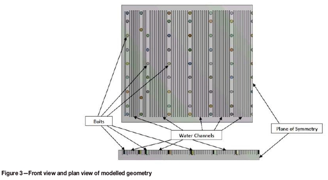
The dimensions of the modelled plate are 2000 mm χ 900 mm. To take advantage of symmetry, only half of the plate is modelled, together with the cooling water channels and clamping bolts. Figure 3 represents the frontal and plan views of the modelled geometry.
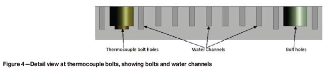
The water channels adjacent to the bolts are extended deeper into the plate to take care of the extra heat flux, since there is no heat extraction at the bolt locations.
Thermocouple bolts are also set a little deeper into the plate to accommodate the thermocouples. Figure 4 shows a detail view of these locations for clarification.
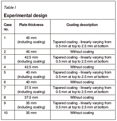
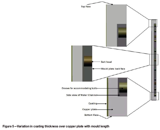
The coating pattern on the mould plate can be understood by referring to Figure 5. The figure shows the tapered nature of the coating, starting with a thickness of 0.5 mm at the top and increasing to 2.5 mm at the bottom, thus keeping the plate thickness constant. This variable coating thickness is necessary because the shell thickness increases with increasing depth in the mould, and thus the pressure on the mould walls, and in turn the wearing tendency, increases. More wear is expected near the bottom of mould, and to counteract this a thicker coating of hard material is applied. The thickness of the copper is therefore reduced to compensate for increased hard material thickness, in order to keep the total plate thickness constant. Reducing the copper thickness will decrease the rate of heat extraction, so the thickness of the coating material has to be chosen judiciously and optimized considering the trade-off between increased strength for wear resistance and the resultant reduction in heat transfer.
Experimental design
Table I shows the experimental design for the parametric study on the effect of coating thickness on hot face temperature.
Mathematical heat flow model
In the mould plate, heat is transferred to the hot face from the solidifying molten steel and removed by water flowing in the water channels on the cold face. The objective of this work requires obtaining the thermal profile of the hot face of the mould plate. The presence of cooling channels and the bolt holes requires the heat transfer to be calculated in three dimensions, and so the Fourier equation for three-dimensional heat transfer across the plate, along with applicable boundary condition, is applied (Meng and Thomas, 2003; Park et al., 2002; Santillana et al., 2008).
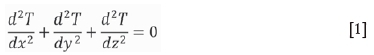
where T is temperature and x, y, z are the length, thickness, and width of the mould plate.
Figure 6 is a schematic representation of the heat transfer model. The heat flux profile on the hot face is also shown.
Assumptions
► The casting speed is assumed to be constant throughout the analysis period (Park et al., 2000)
► The solidifying shell is assumed to be in perfect contact with the copper plate, without any gap (Santillana et al., 2008).
Boundary conditions applied
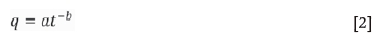
► The hot face is applied with the heat flux boundary condition as shown in Figure 6. The heat flux profile is calculated based on plant measurements of mould water flow rate and rise in water temperature. This incorporates the effects of different layers formed within the mould (air gap, liquid slag, powder, and liquid steel). The applied heat flux profile is linear from the mould top to the peak heat flux location (slightly below the meniscus). Below the peak heat flux location, the heat flux profile in the mould is calculated based on the power law equation (Thomas et al., 1997; Thomas, 2001; Park et al., 2000; Meng and Thomas, 2003; Paul et al., 2000) as in Equation [2].
where
q = mould heat flux (w/m?)
t = residence time inside mould (seconds)
'a' and 'b' are empirical constants adjusted based on total heat removed from the plate.
Since the casting speed is assumed to be constant, the distance x travelled inside the mould will be directly proportional to time (t). For the considered case where mould length is 900 mm and the meniscus is 70 mm below the top of the mould, based on plant calculations heat flux 'q is given as:
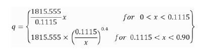
where x is the distance in metres from the mould top (refer Figure 6).
► The mould plate back face, bolt heads, mould plate top face, and mould plate bottom face are taken as being adiabatic and zero wall heat flux is given as the boundary condition
► The faces of the water channels will be the walls from which heat is removed by cooling water through convective heat transfer (Figure 6). Heat extracted qout (w/m2) is given as
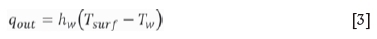
where
Tw(K) is the temperature of the cooling water, for which a linear distribution is assumed from inlet to outlet Tsurf (K) is the surface temperature of the water channel hw(w/m2.K) is the water channel heat transfer coefficient, calculated using the Sleicher Rouse equation (Burmesiter, 1993; Sleicher and Rouse, 1975) as
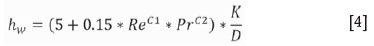
where
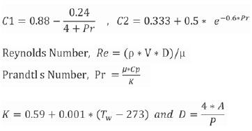
where
ρ = density of water (kg/m3)
μ = viscosity of water (kg/m.s)
V = velocity of water in cooling channels (m/s)
Cp = specific heat capacity of water (J/kg.K)
D = hydraulic diameter of water channel (m)
K = thermal conductivity of water (W/m.K)
A = cross-sectional area of the water channel (m2)
P = perimeter of the cross-section of water channel (m).
Results and discussion
Temperature distribution across the mould plate
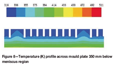
The typical temperature distribution (in K) across the mould plate is shown in Figures 7 and 8. The maximum temperature values can be observed at the meniscus, where peak heat flux is applied, with lower temperatures at locations further into the mould.
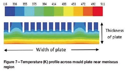
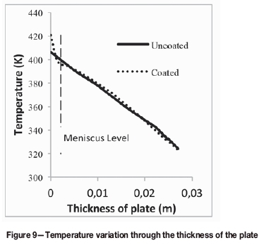
It can be observed from Figure 9 that there is an almost linear temperature gradient across the mould plate from the hot face to the roots of the water channels.
Effect of coating on peak hot face temperature
A nickel coating has been applied over the hot face of the mould as indicated in Figure 5. The temperature distribution on the hot face for both coated and uncoated plates is shown in Figure 10. It is clearly evident that the temperatures are higher on the coated plate.
The temperature profile appears as regularly undulating horizontal bands. Regions where no water channel is present show a higher temperature than those where a water channel is present, for both the coated and the uncoated plate. Since the highest heat flux is located slightly below the meniscus region, the highest temperature bands are near the meniscus in both cases (Figure 10). Hot spots on the hot face opposite bolt locations form in both the plates, although the intensity of the hot spots is much higher in coated plates. This rise in temperature is due to lower conductivity of the coating material - 91 W/mK for nickel compared to 401 W/mK for copper (TibTech, 2018).
The sudden rise in temperature observed near the bottom of plate may be attributed to the absence of water channels at that location. At these locations, higher temperatures are observed in the case of coated plates compared to uncoated plates.
Effect of plate thickness on hot face peak temperature
Five different thicknesses of mould plate, as described in the experimental design, were chosen for analysing the effects of (a) variations in mould plate thickness and (b) plate coatings of different thicknesses on hot face temperature.
These analyses were conducted keeping all other boundary conditions constant. The hot face temperature profile mimics the heat flux profile applied, indicating clearly that, barring the regions close to bolt holes or water channels, the heat transfer across the plate is largely one-dimensional. Similar results have been reported in the literature (Thomas, 2001; Santillana et al, 2008). Figure 11 shows the temperature variation on the hot face along the length (x) of the mould for different plate thicknesses. The figure also indicates that thicker plates have a higher hot face temperature due to the greater resistance to heat flow.
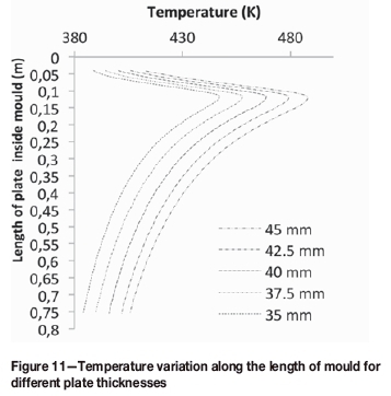
Table II lists peak hot face temperatures recorded for various plate thicknesses under the same boundary conditions and tabulates the rise in temperature due to coating on different plate thicknesses. Coated mould plates have a higher temperature profile and also show higher peak temperatures. This is as expected since the coating material has a lower thermal conductivity (91 W/mK) than the copper (401 W/mK) (TibTech, 2018), and hence the rate of heat transfer through the coating material will be lower.
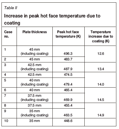
It is quite evident that the effect of the coating increases with decreasing plate thickness, as shown by the greater rise in temperature for thinner plates. This can be attributed to the fact that, for same coating thickness, the ratio of coating material to copper increases. Thus the resistance to heat transfer due to the coating (¾^) increases in comparison to the resistance offered by copper plate (¾¾, where d is the thickness of material and k is the thermal conductivity. The subscripts have the usual meanings.
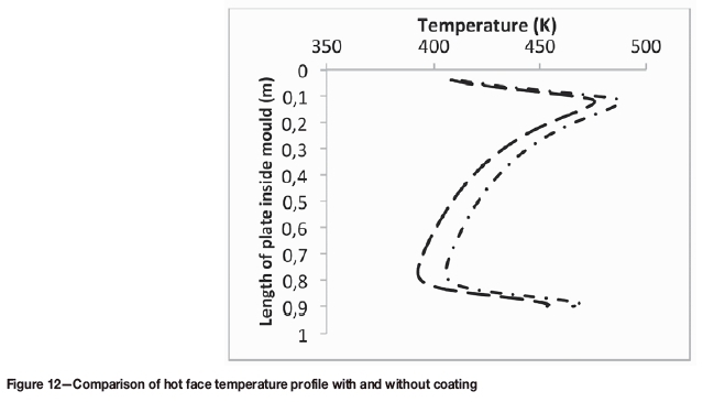
A hot face temperature profile with and without coating for one of the cases is shown in Figure 12. Towards the lower end of the mould, the divergence between the thermal profiles of the coated and uncoated mould increases. This can be explained by the variation in coating thickness, i.e. 0.5 mm at the top of the plate, increasing linearly to 2.5 mm at the bottom of the plate. The greater the contribution of the coating material to the total plate thickness; the greater the temperature difference between the hot face thermal profiles of coated and uncoated moulds. At the lower end of the mould (beyond 0.8 mm) there is a significant rise in temperature for both coated and uncoated moulds. This is due to the absence of cooling channels in this position, owing to design considerations. For a thinner plate, this rise in temperature can be large enough to cause incipient boiling in the cooling channels in the lower portion. This would cause a sudden reduction in heat transfer in the lower portion of mould, which may have a serious impact on the quality of cast slabs.
Effect of bolt holes on hot face temperature
Bolts are essential as they are used to fix the water box to the mould plate. Although bolts are required for completion of the mould assembly and to provide rigidity, they restrict the placing of water channels on the back cold face. Owing to the bolts, hot face temperature fluctuations appear across the width (z) as well as length (x) of the plate. Temperature variation along the length is due to the reduced thickness of copper at the bolt locations, whereas along the width it is due to the absence of water channels at the locations where bolts are positioned. These temperature fluctuations are significant and will cause two-dimensional thermal stresses to develop on the mould hot face, resulting in wear at the locations on the hot face opposite the bolts.
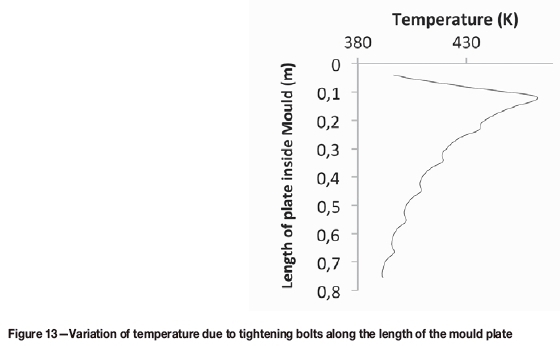
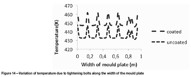
Figures 13 and 14 represent typical variation patterns of mould hot face temperature along the length and the width of the plate respectively. Figure 13 is a longitudinal cross-section along the mould length taken on the hot face opposite to the bolt holes. In Figure 14, zero represents the centre of the plate, and 1 the side.
The inflexions in the curve along the length of mould are at the locations of bolt holes. These zones experience localized temperature fluctuations on the mould plate hot face. Similarly, in Figure 14 the peaks along the curve represent the rise in temperature of the hot face at the bolt locations. This resembles a two-dimensional temperature fluctuation on the hot face at locations where tightening bolts are present on back side, which may result in localized regions of thermal stress, possibly leading to wear and damage of the mould plate and coating at these spots.
The effect of bolts on the hot face temperature becomes more pronounced as the thickness of the mould plate decreases. This is evident from Figure 15, which compares the hot face temperature profiles of plates with different copper thicknesses.
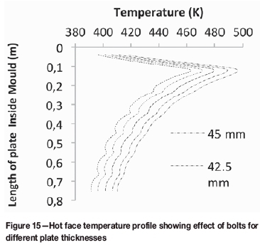
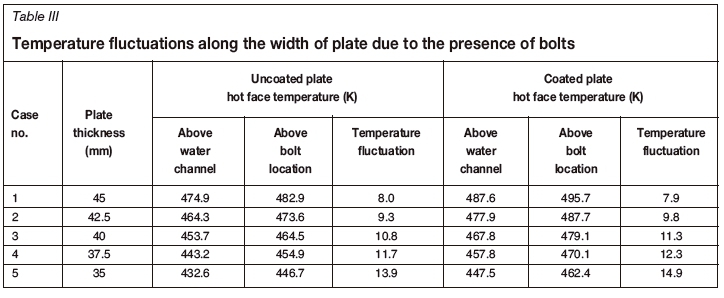
Table III compares the peak hot face temperature and the temperature opposite the cooling channel at the same location below the mould, for both coated and uncoated mould plates. The difference is around 8K for thicker plates. For thinner plates this difference rises to around 14K for an uncoated plate and 15K for a coated plate. The results indicate that the temperature variation across the width of the mould is practically same for both coated and uncoated thicker plates. However, in thinner plates a slight variation in temperature appears, with the coated plate showing a higher temperature.
This variation in temperature can be significant enough to cause thermal distortion on the mould plate. Thus, there is an optimum thickness of the mould plate below which the mould plates can be used with strict monitoring of cast steel quality parameters. In case of a coated mould plate this control is much more critical as the variation in mould face temperature is greater.
It can be noted that with a decrease in plate thickness, the highest temperature on the mould plate decreases. This is applicable for both coated and uncoated plates for all corresponding locations. A lower hot face temperature indicates improved heat transfer across the plate. Also, a thinner plate will be less costly than a thicker plate. Thus, it can be seen that a reduction in plate thickness on the one hand enhances the heat transfer, while on the other hand, thinner copper plates lead to greater variation in hot face temperature across the width of the mould in the meniscus region. This results in higher thermal stresses on thinner mould plates, which may result in accelerated wear of the mould. Coating of such mould plates may aggravate the situation as coated mould plates show a higher temperature variation compared to uncoated mould plate.
Conclusion
This work explains the thermal variations that can be observed along different dimensions of a mould plate due to factors like coating, tightening bolts, coating thickness, plate thickness etc. Temperature variation along the cross-section is more or less one-dimensional, hence 1D analysis could be helpful while focusing on overall temperature distribution. However, 1D analysis cannot capture the fluctuations due to the presence of bolt holes, absence of water channels at certain locations, and variation in temperature along the mould length due to a varying heat flux profile. 3D analysis hence plays an important role in capturing these details of mould heat transfer phenomena.
The results of the analysis show that hot face temperatures decrease with reduction in plate thickness at similar cooling water conditions. A reduction in hot face temperature is desirable as it increases the heat transfer rate. On the other hand, a reduction in plate thickness leads to greater temperature fluctuations at the bolt hole locations, which in turn will result in higher thermal stresses with a reduction in plate thickness. Thus, the optimum mould plate thickness has to be selected judiciously, taking into account both these contradictory features. There is an optimum thickness for the mould plates, below which the mould plates should not be used for casting, whether coated or uncoated.
Acknowledgment
The authors would like to thank the managements of RDCIS, SAIL India, and Bokaro Steel Limited (BSL) India for permission to publish this document. Special thanks are due to the casting personnel of the BSL continuous casting shop for their involvement and help with plant measurements.
References
Burmesiter, L.C. 1993. Convective Heat Transfer. 2nd edn. Wiley, New York. [ Links ]
Chow, C., Samarasekera, I.V., Walker, B.N., and. Lockhart, G. 2002. High speed continuous casting of steel billets-part 2: mould heat transfer and mould design. Ironmaking and Steelmaking, vol. 29, no. 1. pp. 61-69. [ Links ]
CISDI Engineering. 2011. CISDI successfully develops China's first hydraulic width-adjustable mold. http://www.cisdigroup.com/news4-843.html [ Links ]
Continuous Casting Consortium. 2011. Introduction to continuous casting. University of Illinois. http://ccc.illinois.edu/introduction/overview.html#techniques [ Links ]
Janik, M. and Dyja, H. 2004. Modelling of three-dimensional temperature field inside the mould during continuous casting of steel. Journal of Materials Processing Technology, vol. 157-158. pp. 177-182. [ Links ]
Janik, M., Dyja, H., Berski, S., and Banaszek, G. 2004. Two-dimensional thermomechanical analysis of continuous casting process. Journal of Materials Processing Technology, vol. 153-154. pp. 578-582. [ Links ]
Liu, X. and Zhu, M. 2006. Finite element analysis of thermal and mechanical behaviour in a slab continuous casting mold. ISIJ International, vol. 46, no. 11. pp. 1652-1659. [ Links ]
Meng, Y. and Thomas, B.G. 2003. Heat-transfer and solidification model of continuous slab casting. Metallurgical and Materials Transactions B, vol. 34, no. 5. pp. 685-705. [ Links ]
Park, J.K,. Thomas, B.G,. Samarasekera, I.V., and Yoon, U.S. 2002. Thermal and mechanical behavior of copper molds during thin-slab casting. (I). Plant trial and mathematical modelling. Metallurgical and Materials Transactions B, vol. 33B. pp. 1-12. [ Links ]
Park, J.K., Samarasekera, I.V., Thomas, B.G., and Yoon, U.S. 2000. Analysis of thermal and mechanical behavior of copper mould during thin slab casting. Proceedings of the 83rd Steelmaking Conference, Pittsburgh, PA, 26-29 March 2000. Iron and Steel Society, Warrendale, PA. [ Links ]
Paul, A., Pradhan, N., Ray, A.K., Bhor, P.K., Mazumdar, S., and Korath, J.M. 2000. Assessment of heat extraction through slab caster mould. Scandinavian Journal of Metallurgy, vol. 29, no. 4. pp. 139-145. [ Links ]
Samarasekera, I.V. and Brimacombe, J.K. 1979. The thermal field in continuous-casting moulds. Canadian Metallurgical Quarterly, vol. 18, no. 3. pp. 251-266. pp. 9-21. [ Links ]
Samarasekera, I.V. and Brimacombe, J.K. 1982. Mechanical behaviour of continuous-casting billet moulds. Ironmaking and Steelmaking, vol. 9, no. 1. pp. 1-15. [ Links ]
Santillana, B,. Hibbler, L.C., Thomas, B.G., Hamoen, A., Kamperman, A., and van der Knoop, W.V.D. 2008. Heat transfer in funnel-mould casting: effect of plate thickness. ISIJ International, vol. 48, no. 10. pp. 1380-1388. [ Links ]
Sleicher, CA. and Rouse, M.W. 1975. A convenient correlation for heat transfer to constant and variable property fluids in turbulent pipe flow. International Journal of Heat and Mass Transfer, vol. 18, no. 5. pp. 677-683. [ Links ]
Thomas, B.G. 2001. Modeling of the continuous casting of steel - past, present and future. Brimacombe Lecture: Proceedings of the 59th Electric Furnace Conference, Phoenix, AZ . Iron and Steel Society, Warrendale, PA. [ Links ]
Thomas, B.G., Li, G., Moitra, A., and Habing, D. 1997. Analysis of thermal and mechanical. behavior of copper molds during. continuous casting of steel slabs. Proceedings of the 80th Steelmaking Conference, Chicago, IL, 13-16 April 1997. Iron and Steel Society, Warrendale, PA. [ Links ]
TibTech. 2018. Properties table of stainless steel, metals and other conductive materials. http://www.tibtech.com/conductivity.php [ Links ]
Tradekey. 2018. Mould copper plates for slab caster. http://www.tradekey.com/product-free/Mould-Copper-Plates-For-Slab-Caster-984450.html [ Links ]
World Steel Association. 2000, 2009, and 2017. Steel Statistical Yearbook. https://www.worldsteel.org/steel-by-topic/statistics/steel-statistical-yearbook.html [ Links ]
Paper received June 2017
Revised paper received Dec. 2017

